One-Step Stepped Center Pins
Single transition stepped center pins designed to support sliding hollow sleeves. Available in cylindrical or anti-rotational flat-sided configurations.
Products
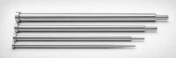
JIS Standard M2 Steel One-Step Center Pins Flat-Sided
One-Step Center Pins flat-sided design for stable locating in one-step molds. (SKH51 steel) for wear resistance and a...
View Details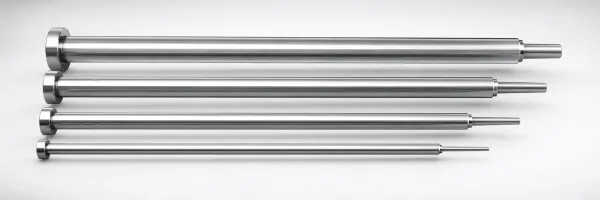
JIS Standard SKH51 Steel One-Step Center Pins
One-Step Center Pins (SKH51 steel) for jigs and dies. JIS-standard manufacture with tight shaft diameter control and ...
View Details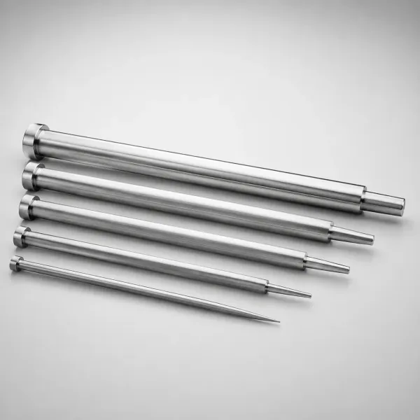
JIS Standard M2 Steel One-Step Center Pins
JIS Standard M2 Steel One-Step Center Pins for accurate mold centering. One-step geometry, SKH51-hardened performance...
View Details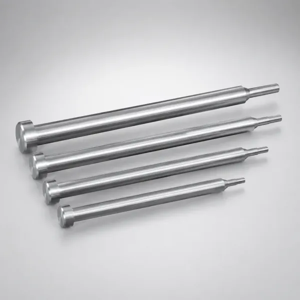
SKH51 Steel One-Step Center Pins
SKH51 steel One-Step Center Pins for accurate sleeve location and stable alignment. One-step geometry supports consis...
View Details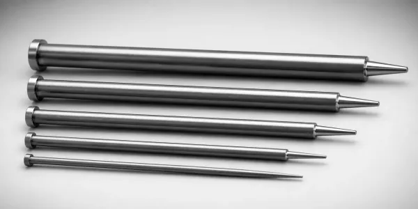
DIN Standard SKD61 Steel One-Step Center Pins (Nitrided)
DIN Standard SKD61 steel One-Step Center Pins (nitrided) provide stable one-step location with tight shaft fits for t...
View Details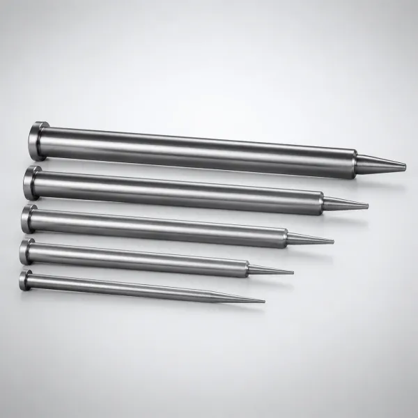
DIN Standard SKD61 Steel One-Step Center Pins Flat-Sided,...
One-Step Center Pins Flat-Sided with nitrided SKD61 steel for stable locating in dies. Designed for accurate fit to H...
View Details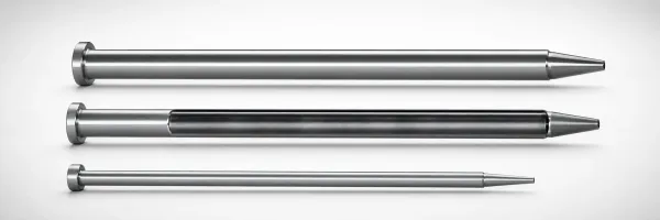
SKD61 Steel One-Step Center Pins with Cooling Hole
SKD61 Steel One-Step Center Pins with Cooling Hole feature nitrided surface treatment for wear resistance. One-step d...
View Details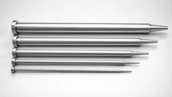
DIN Standard SKD61 Steel One-Step Center Pins
One-Step Center Pins (SKD61 steel) DIN standard for precise mold positioning. One-step design and 4 mm head support s...
View Details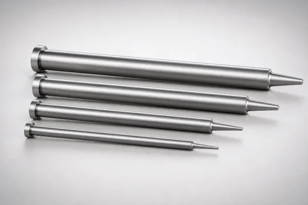
SKD61 Steel One-Step Center Pins One-Step
One-Step Center Pins (SKD61 steel) with a 4 mm head support stable alignment during mold assembly. Configurable tips ...
View Details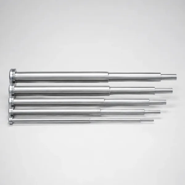
JIS Standard M2 Steel Stepped One-Step Center Pins
JIS Standard M2 Steel Stepped One-Step Center Pins for precise mold positioning. Built for stable centering, durable ...
View DetailsSelection Matrix: JIS vs. DIN Standard One-Step Pins
Verify dimensional differences when swapping between JIS and DIN standard core pins:
| Standard Specification | Head Diameter (K) | Head Thickness (T) | Interchangeability Note |
|---|---|---|---|
| JIS Standard | Slightly smaller (e.g. D+3mm) | Thin head: T = 4.00mm (+0/-0.02) | Common in Asian electronic and automotive mold standards. |
| DIN Standard | Slightly larger (e.g. D+4mm) | Thick head: T = 5.00mm (+0/-0.02) | Requires deeper pocket machining; standard in European molds. |
Decision rule: First verify JIS or DIN based on your mold plate origin — they are not interchangeable. Then choose extra-precision only if your bore clearance is under 0.01 mm. For material grade selection, see our material comparison guide.
Boundary Check: Cylindrical vs. Flat-Sided Core Pins
Ensure correct rotational locking selection for your mold core inserts:
Choose Flat-Sided (Positioning) Pins If:
- The core pin tip has an angled, slotted, or non-symmetrical molding feature.
- The core pin must be locked in a fixed rotation to prevent part mismatch.
Choose Standard Cylindrical Pins If:
- The core pin tip is flat and symmetrical.
- No anti-rotational backing pocket machining is available on plates.
Application Scenarios: One-Step Stepped Pins
Key industrial applications for one-step center core pins:
Deep Boss Vacuum Stiction
During mold opening, deep-cavity plastic parts stick tightly to core pins due to vacuum pressure, stalling cycle times.
Why it fits: The stepped shoulder profile breaks vacuum stiction by admitting air pressure between the core and sleeve.
Angled Molding Surfaces
Cores forming non-symmetrical, angled inner bosses rotate under plastic pressure, causing mold misalignment.
Why it fits: The flat-sided head locks rotation, ensuring the angled core tip stays perfectly aligned.
Frequently Asked Questions
How do JIS standard and DIN standard one-step center pins differ in head dimensions?+
When is a flat-sided positioning one-step center pin required instead of a round one?+
How does a one-step pin prevent vacuum stiction during part ejection?+
About One-Step Stepped Center Pins
One-step center pins have a single diameter transition between the head and the molding shaft. This design provides a guided fit through the ejector plate while the smaller-diameter tip forms the core of the boss or hole. Available in JIS and DIN standards with cylindrical or flat-sided (anti-rotation) configurations. Flat-sided variants lock into the backing plate to prevent angular misalignment on non-symmetrical features.
Engineering Resources
Need a Custom Quote?
Specify head style (JIS/DIN), head thickness, shaft diameter, and cylindrical or flat-sided configuration. Custom lengths and tolerance upgrades available.