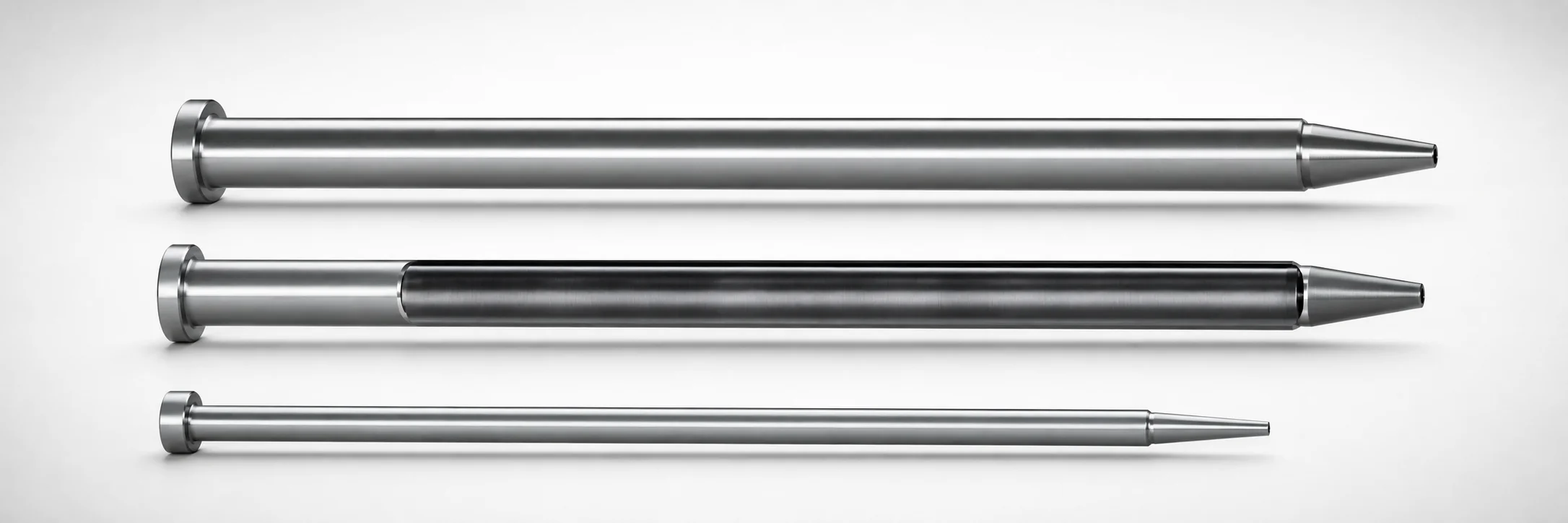
SKD61 Steel One-Step Center Pins with Cooling Hole
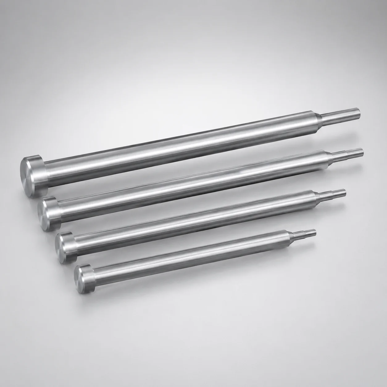
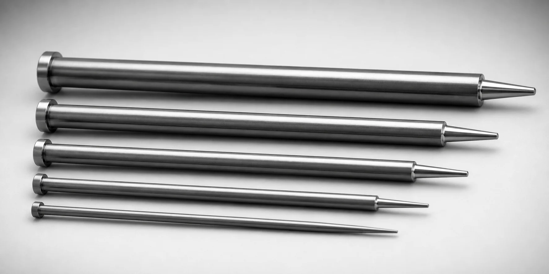
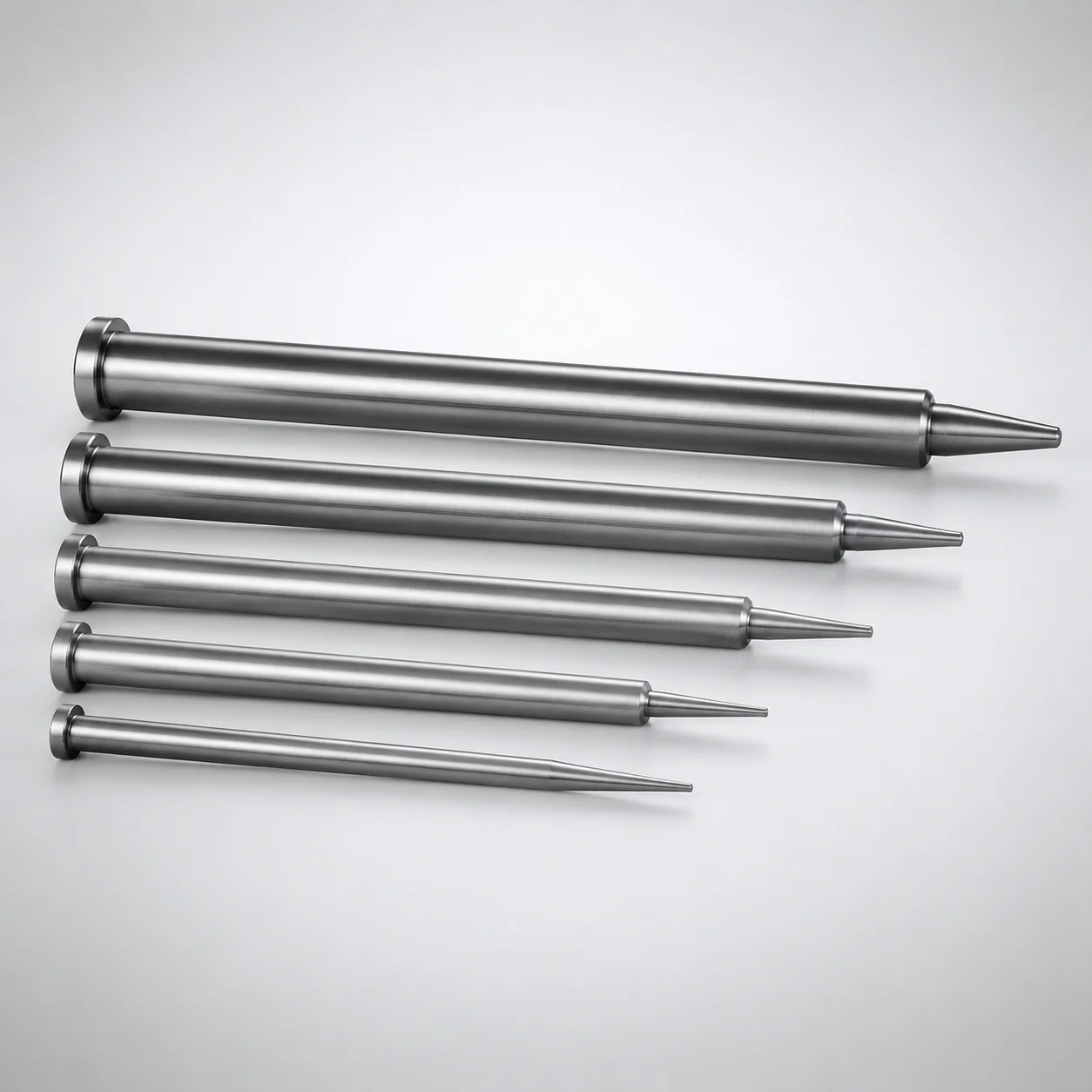
One-Step center pins with cooling hole (SKD61 steel) are built with a nitrided surface to support reliable wear resistance in tooling applications. The one-step form simplifies positioning while the cooling hole helps manage heat during operation.
- One-step geometry for consistent centering and stable locating in mold assemblies
- Nitrided surface treatment improves abrasion resistance under repeated cycles
- Cooling hole design supports temperature control for smoother molding performance
- SKD61 hardened steel construction suitable for precision tool and die use
Specifications
360 configurations available
| Head Thickness | D/P (Shaft Diameter) (mm) | Step Shape | Tip Shape | A (Tip part) (mm) | C (Tip part) (mm) | F (Shaft diameter length) (mm) | G (Tip C chamfering width on the tip part) (mm) | K (Tip part angle) (°) | L (L dimension) (mm) | Q (Tip R chamfering on the tip part) (mm) | R (Tip part) (mm) | S (Tip tapered width on the tip part) (mm) | V (Tip diameter in the tip part) (mm) | W (Cooling hole diameter) (mm) | type |
|---|---|---|---|---|---|---|---|---|---|---|---|---|---|---|---|
| 6mm(JIS) | 6 | A | No processing | - | - | 70 ~ 149.5 | - | - | 70 ~ 150 | - | - | - | 5 ~ 5.99 | 3 | - |
| 6mm(JIS) | 7 | A | No processing | - | - | 70 ~ 149.5 | - | - | 70 ~ 150 | - | - | - | 6 ~ 6.99 | 3 | - |
| 8mm(JIS) | 8 | A | No processing | - | - | 70 ~ 199.5 | - | - | 70 ~ 200 | - | - | - | 7 ~ 7.99 | 4 | - |
| 8mm(JIS) | 10 | A | No processing | - | - | 70 ~ 249.5 | - | - | 70 ~ 250 | - | - | - | 8 ~ 9.99 | 5 ~ 6.5 | - |
| 8mm(JIS) | 12 | A | No processing | - | - | 70 ~ 249.5 | - | - | 70 ~ 250 | - | - | - | 9 ~ 11.99 | 6 ~ 8.5 | - |
| 8mm(JIS) | 15 | A | No processing | - | - | 70 ~ 249.5 | - | - | 70 ~ 250 | - | - | - | 9 ~ 14.99 | 6 ~ 11.5 | - |
| 8mm(JIS) | 16 | A | No processing | - | - | 70 ~ 249.5 | - | - | 70 ~ 250 | - | - | - | 9 ~ 15.99 | 6 ~ 12.5 | - |
| 6mm(JIS) | 6 | A | B | - | - | 70 ~ 149.5 | - | - | 70 ~ 150 | - | - | - | 5 ~ 5.99 | 3 | - |
| 6mm(JIS) | 7 | A | B | - | - | 70 ~ 149.5 | - | - | 70 ~ 150 | - | - | - | 6 ~ 6.99 | 3 | - |
| 8mm(JIS) | 8 | A | B | - | - | 70 ~ 199.5 | - | - | 70 ~ 200 | - | - | - | 7 ~ 7.99 | 4 | - |
| 8mm(JIS) | 10 | A | B | - | - | 70 ~ 249.5 | - | - | 70 ~ 250 | - | - | - | 8 ~ 9.99 | 5 ~ 6.5 | - |
| 8mm(JIS) | 12 | A | B | - | - | 70 ~ 249.5 | - | - | 70 ~ 250 | - | - | - | 9 ~ 11.99 | 6 ~ 8.5 | - |
| 8mm(JIS) | 15 | A | B | - | - | 70 ~ 249.5 | - | - | 70 ~ 250 | - | - | - | 9 ~ 14.99 | 6 ~ 11.5 | - |
| 8mm(JIS) | 16 | A | B | - | - | 70 ~ 249.5 | - | - | 70 ~ 250 | - | - | - | 9 ~ 15.99 | 6 ~ 12.5 | - |
| 6mm(JIS) | 6 | A | C | - | - | 70 ~ 149.5 | 0.5 ~ 2.9 | - | 70 ~ 150 | - | - | - | 5 ~ 5.99 | 3 | - |
| 6mm(JIS) | 7 | A | C | - | - | 70 ~ 149.5 | 0.5 ~ 3.4 | - | 70 ~ 150 | - | - | - | 6 ~ 6.99 | 3 | - |
| 8mm(JIS) | 8 | A | C | - | - | 70 ~ 199.5 | 0.5 ~ 3.9 | - | 70 ~ 200 | - | - | - | 7 ~ 7.99 | 4 | - |
| 8mm(JIS) | 10 | A | C | - | - | 70 ~ 249.5 | 0.5 ~ 4.9 | - | 70 ~ 250 | - | - | - | 8 ~ 9.99 | 5 ~ 6.5 | - |
| 8mm(JIS) | 12 | A | C | - | - | 70 ~ 249.5 | 0.5 ~ 5.9 | - | 70 ~ 250 | - | - | - | 9 ~ 11.99 | 6 ~ 8.5 | - |
| 8mm(JIS) | 15 | A | C | - | - | 70 ~ 249.5 | 0.5 ~ 7.4 | - | 70 ~ 250 | - | - | - | 9 ~ 14.99 | 6 ~ 11.5 | - |
| 8mm(JIS) | 16 | A | C | - | - | 70 ~ 249.5 | 0.5 ~ 7.9 | - | 70 ~ 250 | - | - | - | 9 ~ 15.99 | 6 ~ 12.5 | - |
| 6mm(JIS) | 6 | A | G | - | - | 70 ~ 149.5 | - | 21 ~ 60 | 70 ~ 150 | - | - | - | 5 ~ 5.99 | 3 | - |
| 6mm(JIS) | 7 | A | G | - | - | 70 ~ 149.5 | - | 21 ~ 60 | 70 ~ 150 | - | - | - | 6 ~ 6.99 | 3 | - |
| 8mm(JIS) | 8 | A | G | - | - | 70 ~ 199.5 | - | 21 ~ 60 | 70 ~ 200 | - | - | - | 7 ~ 7.99 | 4 | - |
| 8mm(JIS) | 10 | A | G | - | - | 70 ~ 249.5 | - | 21 ~ 60 | 70 ~ 250 | - | - | - | 8 ~ 9.99 | 5 ~ 6.5 | - |
| 8mm(JIS) | 12 | A | G | - | - | 70 ~ 249.5 | - | 21 ~ 60 | 70 ~ 250 | - | - | - | 9 ~ 11.99 | 6 ~ 8.5 | - |
| 8mm(JIS) | 15 | A | G | - | - | 70 ~ 249.5 | - | 21 ~ 60 | 70 ~ 250 | - | - | - | 9 ~ 14.99 | 6 ~ 11.5 | - |
| 8mm(JIS) | 16 | A | G | - | - | 70 ~ 249.5 | - | 21 ~ 60 | 70 ~ 250 | - | - | - | 9 ~ 15.99 | 6 ~ 12.5 | - |
| 6mm(JIS) | 6 | A | R | - | - | 70 ~ 149.5 | - | - | 70 ~ 150 | 0.2 ~ 2.9 | - | - | 5 ~ 5.99 | 3 | - |
| 6mm(JIS) | 7 | A | R | - | - | 70 ~ 149.5 | - | - | 70 ~ 150 | 0.2 ~ 3.4 | - | - | 6 ~ 6.99 | 3 | - |
| 8mm(JIS) | 8 | A | R | - | - | 70 ~ 199.5 | - | - | 70 ~ 200 | 0.2 ~ 3.9 | - | - | 7 ~ 7.99 | 4 | - |
| 8mm(JIS) | 10 | A | R | - | - | 70 ~ 249.5 | - | - | 70 ~ 250 | 0.2 ~ 4.9 | - | - | 8 ~ 9.99 | 5 ~ 6.5 | - |
| 8mm(JIS) | 12 | A | R | - | - | 70 ~ 249.5 | - | - | 70 ~ 250 | 0.2 ~ 5.9 | - | - | 9 ~ 11.99 | 6 ~ 8.5 | - |
| 8mm(JIS) | 15 | A | R | - | - | 70 ~ 249.5 | - | - | 70 ~ 250 | 0.2 ~ 7.4 | - | - | 9 ~ 14.99 | 6 ~ 11.5 | - |
| 8mm(JIS) | 16 | A | R | - | - | 70 ~ 249.5 | - | - | 70 ~ 250 | 0.2 ~ 7.9 | - | - | 9 ~ 15.99 | 6 ~ 12.5 | - |
| 6mm(JIS) | 6 | A | T | - | - | 70 ~ 149.5 | - | 21 ~ 45 | 70 ~ 150 | - | - | 0.1 ~ 50 | 5 ~ 5.99 | 3 | - |
| 6mm(JIS) | 7 | A | T | - | - | 70 ~ 149.5 | - | 21 ~ 45 | 70 ~ 150 | - | - | 0.1 ~ 50 | 6 ~ 6.99 | 3 | - |
| 8mm(JIS) | 8 | A | T | - | - | 70 ~ 199.5 | - | 21 ~ 45 | 70 ~ 200 | - | - | 0.1 ~ 50 | 7 ~ 7.99 | 4 | - |
| 8mm(JIS) | 10 | A | T | - | - | 70 ~ 249.5 | - | 21 ~ 45 | 70 ~ 250 | - | - | 0.1 ~ 50 | 8 ~ 9.99 | 5 ~ 6.5 | - |
| 8mm(JIS) | 12 | A | T | - | - | 70 ~ 249.5 | - | 21 ~ 45 | 70 ~ 250 | - | - | 0.1 ~ 50 | 9 ~ 11.99 | 6 ~ 8.5 | - |
| 8mm(JIS) | 15 | A | T | - | - | 70 ~ 249.5 | - | 21 ~ 45 | 70 ~ 250 | - | - | 0.1 ~ 50 | 9 ~ 14.99 | 6 ~ 11.5 | - |
| 8mm(JIS) | 16 | A | T | - | - | 70 ~ 249.5 | - | 21 ~ 45 | 70 ~ 250 | - | - | 0.1 ~ 50 | 9 ~ 15.99 | 6 ~ 12.5 | - |
| 6mm(JIS) | 6 | B | No processing | 5 ~ 5.99 | - | 70 ~ 149.5 | - | - | 70 ~ 150 | - | - | - | 5 ~ 5.99 | 3 | - |
| 6mm(JIS) | 7 | B | No processing | 6 ~ 6.99 | - | 70 ~ 149.5 | - | - | 70 ~ 150 | - | - | - | 6 ~ 6.99 | 3 | - |
| 8mm(JIS) | 8 | B | No processing | 7 ~ 7.99 | - | 70 ~ 199.5 | - | - | 70 ~ 200 | - | - | - | 7 ~ 7.99 | 4 | - |
| 8mm(JIS) | 10 | B | No processing | 8 ~ 9.99 | - | 70 ~ 249.5 | - | - | 70 ~ 250 | - | - | - | 8 ~ 9.99 | 5 ~ 6.5 | - |
| 8mm(JIS) | 12 | B | No processing | 9 ~ 11.99 | - | 70 ~ 249.5 | - | - | 70 ~ 250 | - | - | - | 9 ~ 11.99 | 6 ~ 8.5 | - |
| 8mm(JIS) | 15 | B | No processing | 9 ~ 14.99 | - | 70 ~ 249.5 | - | - | 70 ~ 250 | - | - | - | 9 ~ 14.99 | 6 ~ 11.5 | - |
| 8mm(JIS) | 16 | B | No processing | 9 ~ 15.99 | - | 70 ~ 249.5 | - | - | 70 ~ 250 | - | - | - | 9 ~ 15.99 | 6 ~ 12.5 | - |
| 6mm(JIS) | 6 | B | B | 5 ~ 5.99 | - | 70 ~ 149.5 | - | - | 70 ~ 150 | - | - | - | 5 ~ 5.99 | 3 | - |
Product Guide
Application Scenarios+
This SKD61 one-step center pin variant is used inside injection mold toolsets where repeatable alignment between moving and fixed components is critical. Its one-step geometry supports stable locating during assembly and operation, helping reduce misalignment-related flash and dimensional drift.
- Automotive connector and bracket molds: Use the locating pin to maintain concentricity across cycles while the integrated cooling hole supports heat management near the reference feature.
- Electronics housings and insulating parts: The nitrided surface is suitable for molds that see high wear from repeated ejection/closing actions, improving abrasion resistance on the locating interface.
- Thin-wall plastic components: Consistent positioning helps the core/cavity stay aligned, supporting uniform part thickness; the cooling feature can help stabilize local temperatures around the pin.
These design choices—one-step locating plus a cooling hole and nitrided wear surface—make it well-suited for precision injection molding where alignment and tool longevity both matter.
Material & Process Details+
SKD61 is a hot-work tool steel commonly used in injection mold tooling; it is selected here for its balance of wear resistance and toughness under cyclic thermal and mechanical loading. The meta description indicates a nitrided surface treatment, which forms a hard, wear-resistant surface layer to reduce abrasion from repeated contact.
- Surface performance: Nitriding improves resistance to wear at the locating interface, supporting longer service life in high-cycle molds.
- Core behavior: The underlying SKD61 steel provides toughness so the pin can withstand operational loads without excessive brittleness.
- Heat treatment state: The specified key process is nitriding; the part is supplied as a hardened steel base with a nitrided wear surface (exact HRC is not provided in the input data).
Compared with untreated or softer surface conditions, nitriding trades some processing cost/lead time for substantially improved surface durability. Directly comparing hardness (HRC) or alternative grades is not possible from the provided specifications.
Sizing & Selection Guide+
Select the one-step center pin size by matching the D/P (shaft diameter) and the length (F or L) to your mold’s core/cavity locating requirements. From the provided ranges, the shaft diameter D/P is 6 ~ 16 mm, and the shaft diameter length F is available in ranges such as 70 ~ 149.5, 70 ~ 199.5, 70 ~ 249.5, 50 ~ 249.5, and 50 ~ 240. The overall L dimension is offered as 70 ~ 150, 70 ~ 200, and 70 ~ 250 variants.
- Step and tip geometry: Choose the Step Shape (A, B, C, D, E) and Tip Shape (No processing, B, C, G, R, T) to match the mating locating feature and desired engagement.
- Cooling hole fit: Verify the W (cooling hole diameter) option (e.g., 3, 4, 5 ~ 6.5, 6 ~ 8.5, 6 ~ 11.5, 6 ~ 12.5) is compatible with your tool’s heat-management design.
- Tolerance/fit: The input does not provide tolerance values; use your standard center-pin clearance/spec for the corresponding D/P size and mating bore geometry.
Frequently Asked Questions
Which SKD61 one-step center pin sizes are available for locating, specifically for shaft diameter and length?+
How does the cooling hole diameter (W) affect design compatibility in the mold?+
What step and tip configurations can be selected for mating engagement and centering behavior?+
What is the wear-performance basis of the SKD61 pin variant?+
Are there configurable tip angles and chamfers that influence assembly clearance?+
Related Products
Need Custom Specifications?
Our engineering team can help with custom configurations, material selection, and volume pricing.