Plastic Mold Heating & Cooling
Product Categories
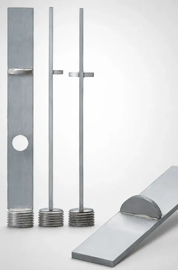
Choose Your Mold Cooling Approach
Injection mold cooling systems vary based on your mold geometry, cycle time targets, and temperature stability. Identify your primary cooling challenge to route to the correct internal, external, or ancillary component category:
Internal Waterline Components (Baffles & Pipes)
Directing flow inside the mold steel. Ideal for straight-drilled channels, deep cores, and localized hot spots. Includes baffles (flat/spiral) and cascade bubbler pipes to split channels into supply and return paths.
Start with → Baffle Boards, Bubbler Pipes & Spot Coolers
High-Efficiency Phase-Change Heat Pipes
Thermal pins (heat pipes) containing a working fluid that evaporates and condenses. Best for extremely narrow cores, thin ribs, or tight areas where water channels cannot be physically drilled.
Start with → Thermal Pins (Heat Pipes)
External Circuit Connection & Distribution
Managing coolant distribution from the mold temperature controller (MTC) or chiller to individual mold zones. Includes multi-port manifolds, hydro-circuit blocks, and quick-disconnect uni-joints.
Start with → Manifolds, Blocks & Circuit Connections
System Seals, Monitoring & Ancillaries
Ensuring high-pressure integrity and thermal tracking. Features water flow checkers for real-time monitoring, high-temp O-rings, aluminum/brass plugs, and air jet units for localized air cooling.
Start with → Flow Checkers, Plugs & O-Rings
Design rule: Mold cooling layout should follow a clear hierarchy: internal heat absorption (baffles/bubblers) → external distribution (manifolds) → system thermal regulation (temperature controllers). For a comprehensive layout design, see our Complete Guide to Injection Mold Cooling System Design.
How Injection Mold Cooling Works
Understanding the three fundamental heat transfer mechanisms (Conduction, Convection, and Phase Change) is essential for predicting cooling efficiency and calculating cycle times.
Conduction: Heat Propagation Through Mold Steel
Heat from the molten polymer (typically 200°C–320°C) is conducted through the mold steel to the cooling channel wall. The conduction rate is governed by Fourier's Law: $q = -k \nabla T$. The thermal conductivity ($k$) of standard P20 mold steel is $\approx 29 \text{ W/m·K}$, whereas beryllium copper (BeCu) inserts offer $\approx 105 \text{ W/m·K}$ (3.6× higher), making BeCu ideal for rapid localized conduction. The pitch-to-diameter ratio ($P/D$) of cooling waterlines should be kept between 2.0 to 3.0, and the steel depth (distance from channel center to cavity surface) should be 1.5 to 2.0× the channel diameter to prevent mold plate deformation while keeping conduction paths short.
Convection: Heat Dissipation to the Coolant Flow
Once heat reaches the channel wall, it is swept away by the flowing coolant via forced convection, described by Newton's Law of Cooling: $q = h(T_w - T_f)$. The convective heat transfer coefficient ($h$) depends heavily on the flow regime, defined by the Reynolds Number: $$Re = \frac{\rho \cdot v \cdot D_h}{\mu}$$ Where $\rho$ is fluid density, $v$ is velocity, $D_h$ is hydraulic diameter, and $\mu$ is dynamic viscosity. Laminar flow ($Re < 2,300$) acts as an insulating boundary layer. True turbulent flow ($Re > 10,000$) increases the heat transfer coefficient $h$ by 300% to 500%. Internal baffles (flat or spiral) and bubblers force turbulent mixing in deep channels. Target velocity is $1.5 \text{ to } 3.0 \text{ m/s}$ to maintain turbulence without causing excessive pump cavitation or pressure drop.
Phase Change: Ultra-High Thermal Pins
For narrow cores where drilling waterlines is impossible due to space constraints, heat pipes (thermal pins) leverage the latent heat of vaporization. A small volume of working fluid inside the vacuum-sealed copper tube undergoes a continuous thermodynamic cycle: $$\text{Evaporation (hot core tip)} \rightarrow \text{Vapor Flow} \rightarrow \text{Condensation (cooled base)} \rightarrow \text{Capillary Return (via wick)}$$ The latent heat of vaporization of water is $\approx 2,260 \text{ kJ/kg}$, giving the heat pipe an equivalent thermal conductivity ($k_{eff}$) of $10,000 \text{ to } 200,000 \text{ W/m·K}$. This is up to 1000× higher than copper, transferring heat instantly from the core tip down to the mold base water channel.
Engineering formula: The required cooling time $t_c$ (which occupies 60-80% of the molding cycle) can be estimated using the polymer thermal diffusivity $\alpha$ and the maximum part wall thickness $s$: $$t_c \approx \frac{s^2}{\pi^2 \alpha} \ln\left(\frac{4}{\pi} \frac{\theta_m - \theta_c}{\theta_e - \theta_c}\right)$$ Where $\theta_m$ is melt temperature, $\theta_e$ is ejection temperature, and $\theta_c$ is average cavity wall temperature. Minimizing $s$ and optimizing $\theta_c$ using turbulent convection are key to minimizing $t_c$. For automatic calculation, access our Mold Cooling Channel Sizing Calculator.
Troubleshooting Mold Cooling Problems
Common injection molding defects caused by cooling issues, with root causes and component-based solutions:
| Problem | Root Cause | Solution |
|---|---|---|
| Warpage / Bowing | Uneven cooling between cavity and core sides — temperature differential >10°C causes asymmetric shrinkage | Add baffles to under-cooled zones; switch to parallel cooling circuits for independent zone control |
| Sink Marks on Thick Sections | Insufficient cooling at thick-wall areas — material continues shrinking after skin solidification | Install thermal pins (heat pipes) at hot spots; use spot cooling pipes for targeted cooling |
| Long Cycle Time | Inadequate overall cooling capacity — laminar flow in channels, insufficient turbulence | Replace flat baffles with spiral baffles for better turbulence; upgrade to high-flow cascade assemblies |
| Coolant Leaks | Degraded O-rings, loose plugs, or corroded pipe threads | Replace O-rings; use pressure plugs with proper torque; apply PTFE seal tape |
| Scale Buildup / Reduced Flow | Mineral deposits in cooling channels from hard water — flow rate drops 20-50% over 6-12 months | Monitor with water flow checkers; schedule preventive descaling; use corrosion-resistant stainless steel cooling pipes |
Diagnostic tip: Start by measuring coolant flow rate at each circuit outlet using a water flow checker. A flow rate drop >30% from baseline indicates scale buildup or blockage. For a systematic troubleshooting workflow, see our Troubleshooting Mold Cooling Problems guide.
Quick Reference: Cooling Components by Waterline Diameter
Quick reference table to match drilled waterline diameters with standard components across all product categories:
| Waterline Diameter | Baffles (Standard Series) | Cooling Pipes (Cascade/Standard) | Waterline Plugs (Threaded/Threadless) | O-Rings (FKM / NBR) |
|---|---|---|---|---|
| ø6 mm | Brass Flat Baffle (BPTF ø6) | SS Bubbler Pipe (KPJH ø6) | Aluminum Expansion Plug (MSPA ø6) | FKM High-Temp O-Ring (ORSO 4.8) |
| ø8 mm | Brass Flat Baffle (BPTF ø8) | Cascade Pipe (KPCF ø8) | Brass Plug (R1/8 Thread, MSPE) | NBR Standard O-Ring (ORSO 6.8) |
| ø10 mm | Brass/Spiral Baffle (BPTF/SPNF ø10) | High-Flow Cascade (KPMF ø10) | Tapered Brass Plug (R1/4, MSPE) | FKM High-Temp O-Ring (ORSO 8.8) |
| ø12 mm | Brass/Spiral Baffle (BPTF/SPNF ø12) | High-Flow Cascade (KPMF ø12) | Tapered Brass Plug (R3/8, MSPE) | FKM High-Temp O-Ring (ORSO 10.8) |
| 1/4" (Inch) | Brass Baffle (PCS-BF-25) | Bubbler Tube (PCS-BT-25) | NPT 1/16 Thread Plug (PCS-NP-06) | NBR Inch O-Ring (AS568-008) |
| 3/8" (Inch) | Brass/Spiral Baffle (PCS-BF-37) | Cascade Pipe (PCS-CP-37) | NPT 1/8 Thread Plug (PCS-NP-12) | NBR Inch O-Ring (AS568-010) |
| 7/16" (Inch) | Brass/Spiral Baffle (PCS-BF-43) | Cascade Pipe (PCS-CP-43) | NPT 1/4 Thread Plug (PCS-NP-25) | NBR Inch O-Ring (AS568-012) |
Sizing rule: In metric molds, ø8-12 mm channels cover 90% of cooling zones. Standardize on the R1/8 to R3/8 tapered threads for waterline connections. For inch-standard molds (common in DME mold bases), 7/16" is the dominant channel size, matching NPT 1/4 thread plugs. Use our Channel Sizing Calculator for precise flow area design.
About Plastic Mold Heating & Cooling Components
Injection mold cooling systems are the single largest factor in determining cycle time, part quality, and mold longevity. Cooling typically accounts for 60-80% of the total cycle, making it the most impactful area for process optimization. A well-designed cooling system ensures uniform temperature distribution across the mold cavity, minimizing warpage, sink marks, and dimensional variation.
Our mold cooling component range covers the complete internal cooling system — from fluid-directing baffles and cooling pipes inside drilled channels, to high-efficiency heat pipes for thermally challenging zones, to cooling circuit manifolds and plugs for external water distribution, plus maintenance tools for long-term system reliability. Components are available in both metric (JIS) and inch standards from MISUMI and PCS brands, with MOQ 1 piece for both standard and custom specifications.
Industry Applications
Automotive Interior & Exterior Parts
Large dashboard panels, bumper covers, and door trim require multi-zone cooling with tight temperature uniformity (±2°C) to prevent warpage on parts exceeding 1 meter in length.
Parallel cooling circuits with independent manifold control ensure each zone reaches the target mold temperature. Heat pipes address deep boss and rib sections that conventional channels cannot reach.
Key components → Cooling Manifolds, Heat Pipes, Spiral Baffles
Medical Device & Packaging
High-cavity molds (32-128 cavities) for syringe barrels, vial caps, and thin-wall containers demand cycle times under 8 seconds with zero dimensional variation between cavities.
Cascade cooling pipes and high-flow assemblies deliver maximum turbulence in tight spaces between cavities. Each cavity needs matched cooling performance — flow checkers verify uniformity.
Key components → High-Flow Cascades, Water Flow Checkers, Precision O-Rings
Consumer Electronics Housings
Thin-wall phone cases, laptop bezels, and connector housings require cosmetic-grade surface finish with no sink marks — any visible cooling line marks are rejected.
Spot cooling pipes target gate areas and thick-to-thin transitions where thermal gradients cause cosmetic defects. PTFE seal tapes prevent any coolant seepage that could contaminate the mold surface.
Key components → Spot Cooling Pipes, Brass Baffles, PTFE Seal Tapes
Frequently Asked Questions
What are the main methods for cooling injection molds?+
How does cooling time affect injection molding cycle time?+
What causes uneven cooling in injection molds?+
How do I calculate the required cooling channel diameter for my mold?+
Can I get custom cooling components with MOQ 1 piece?+
Engineering Resources
The Complete Guide to Injection Mold Cooling System Design
End-to-end overview of cooling system design: channel layout, component selection, and thermal analysis fundamentals.
The Complete Guide to Injection Mold Cooling System Design
End-to-end overview of cooling system design: channel layout, component selection, and thermal analysis fundamentals.
Troubleshooting Mold Cooling Problems: Warpage, Sink Marks & Uneven Temperature
Systematic diagnosis of the 5 most common cooling defects with root cause analysis and component-based solutions.
Mold Cooling Channel Sizing Calculator
Practical formulas and rules of thumb for calculating cooling channel dimensions based on part geometry and resin type.
Mold Cooling Channel Sizing Calculator
Practical formulas and rules of thumb for calculating cooling channel dimensions based on part geometry and resin type.
Need a Custom Quote?
Send your specifications — cooling channel diameter, depth, material preference, and thread standard (metric/inch) — and receive a quote. Custom lengths, diameters, and configurations available across all product lines.