Mold Cooling Circuit Components
Uni-joint plugs, cooling water manifolds, hydro-circuit blocks, and hex key cascade assemblies for managing mold cooling water distribution across multiple independent temperature zones.
All Products (6)
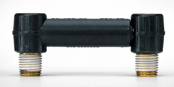
Cooling Uni-Joint Plugs with Flexible Tube Option
Cooling Uni-Joint Plugs with flexible tube option provide heat resistant cooling circuit fittings up to 80°C. Reduce ...
View Details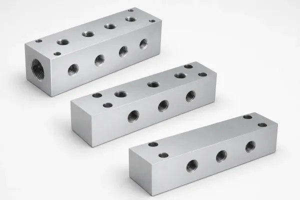
Cooling Water Mold Manifolds - Branching & Aggregating
Cooling Water Mold Manifolds - Branching & Aggregating distribute coolant efficiently through mold systems, stabilizi...
View Details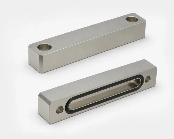
BRJH Hydro-Circuit Blocks for Cooling Water and Oil
BRJH Hydro-Circuit Blocks for Cooling Water and Oil provide heat-resistant thermal management and stable fluid flow. ...
View Details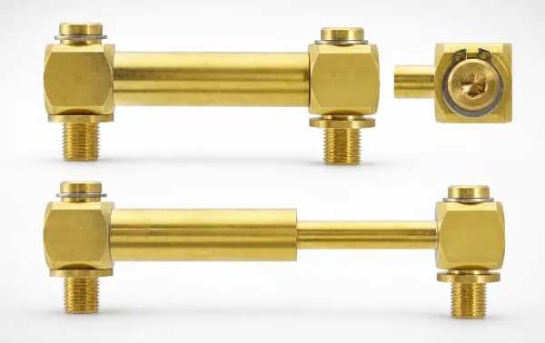
JWRH Cooling Uni-Joint Plugs (Brass) - Extendable Tube
JWRH Cooling Uni-Joint Plugs (Brass) with extendable tube support heat-resistant insulation in cooling circuits. Mini...
View Details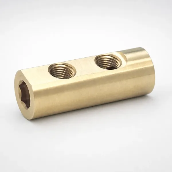
Hex Key Cascade Water Junction Replacement Heads (Brass)
Hex Key Cascade Water Junction replacement heads in brass for high flow tube systems. Designed for minimum clearance ...
View Details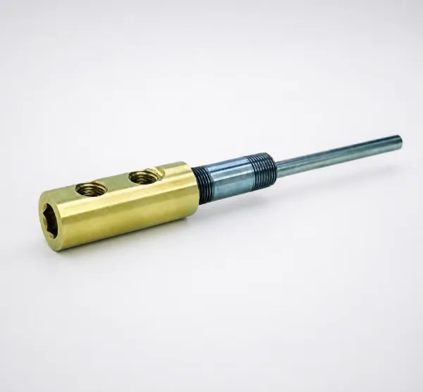
Hex Key Cascade Assemblies (Inch)
Hex Key Cascade Assemblies (Inch) for tight-space fluid routing. Includes stainless steel high-flow tube and nipples ...
View DetailsCooling Circuit Component Selection Guide
Three approaches to cooling water distribution — choose based on your mold complexity, pressure limit, and maintenance requirements.
| Dimension | Uni-Joint Plugs | Water Manifolds | Hydro-Circuit Blocks |
|---|---|---|---|
| Function | Single-point flexible bridge link | Multi-port external waterline branching | Integrated multi-channel manifold block |
| Port Count Range | 1 channel per unit (extendable bellows) | 2 to 8 outlet ports | 4 to 12 cross-drilled internal channels |
| Configuration Flexibility | High (flexible Polyacetal/Urethane tube) | Medium (configurable port fittings) | Low (fixed internal cross-drilled layout) |
| Enveloping Space & Hoses | Minimal footprint | Moderate (requires external branch hoses) | Ultra-compact (mounted directly, zero hoses) |
| Working Temperature & Media | Water only (Max $80^\circ\text{C}$ for plastics) | Water / Glycol (Max $120^\circ\text{C}$, metal body) | Water or heat oil (Max $200^\circ\text{C}$ for steel/brass) |
| Best For | Slide/lifter cooling, tight core gaps | Multi-zone molds, high-flow flex layouts | Standardized B2B mold bases, hot oil regulation |
Selection rule: Use uni-joint plugs for individual channel connections. Use manifolds when you need to split one supply into multiple zones with independent control. Use hydro-circuit blocks for compact, standardized installations or oil-heated molds. See our Manifold vs Hydro-Circuit Block Guide.
Parallel vs Series Cooling Circuits
The circuit topology determines temperature uniformity across your mold. Choose the right layout for your precision requirements.
Parallel Circuits: Uniform Heat Extraction
In parallel cooling, the main supply is branched so that each channel receives fresh coolant directly at the same inlet temperature ($T_{in}$).
Thermal Performance: Maintains strict cavity temperature uniformity, keeping mold temperature gradients ($\Delta T_{mold}$) under $2^\circ\text{C}$. This is critical for preventing asymmetric shrinkage and subsequent part warpage.
Fluid Dynamics: The system total pressure drop equals that of the single branch with the highest flow resistance ($\Delta P_{total} = \Delta P_{branch}$). However, the total volumetric flow rate is the sum of all individual channels ($Q_{total} = \sum Q_i$). Flow balance valves must be used to prevent coolant from short-circuiting through paths of least resistance, which would leave narrower channels in a laminar regime ($Re < 2,300$).
Series Circuits: Simple Plumbing with Cumulative Heating
In series cooling, the coolant flows through all channels sequentially.
Thermal Performance: The coolant absorbs heat continuously, causing its temperature to rise linearly: $$\Delta T_{fluid} = \frac{q}{\dot{m} \cdot C_p}$$ Where $q$ is heat transfer rate, $\dot{m}$ is mass flow rate, and $C_p$ is specific heat capacity. This cumulative heating typically causes downstream cavities to run $3^\circ\text{C}$ to $8^\circ\text{C}$ hotter, leading to cavity-to-cavity shrinkage variation.
Fluid Dynamics: Plumbing is simple (one hose in, one hose out) and the total flow rate equals a single channel ($Q_{total} = Q_{channel}$). However, the total system pressure drop accumulates with every channel: $$\Delta P_{total} = \sum \Delta P_{channel} + \sum \Delta P_{bends}$$ According to the Darcy-Weisbach equation, this high pressure drop can easily exceed the capacity of standard mold chillers, leading to a drastic drop in flow rate and a collapse of heat transfer coefficients.
Design rule: Use parallel circuits for precision applications (medical, optical, electronics) where ΔT < 3°C is required. Use series circuits for commodity parts where ±5°C is acceptable. See our Parallel vs Series Cooling Circuits technical guide.
Component Pairing Guide
Ensure correct sizing and thread standards when pairing circuit distribution blocks with external lines:
Water Manifold Sizing
Aluminum manifolds (MNDF Series) feature Rc3/4 or Rc1 main supply inlets. Match branch ports (Rc1/4 or Rc3/8) with quick-disconnect couplings (KSHW Series) and high-temp rubber hoses.
E.g., Rc3/8 port pairs with ø10 mm barbed socket fittings.Hydro-Block Mounting & Seals
Hydro-blocks (HFCB Series) mount directly to mold base plates. Ensure mounting faces are sealed with FKM high-temperature O-rings (ORSO Series) and torqued using 12.9 class M6/M8 hex bolts.
E.g., HFCB block outlet matches ORSO 8.8-V O-rings.About Mold Cooling Circuit Components
Mold Cooling Circuit Components manage the distribution of coolant water (or oil) across multiple independent zones in the mold. Proper circuit design — parallel vs series topology, flow balancing, and independent zone control — is as important as the cooling channels themselves. Our range covers single-point connections (uni-joint plugs), multi-port distributors (manifolds), and integrated blocks (hydro-circuit blocks) for both water and oil media.
Application Scenarios
Multi-Zone Precision Molds
Large automotive molds with 6-12 independent cooling zones, each requiring precise temperature control to prevent warpage on thin-wall panels.
Manifolds with individual flow control valves per zone enable parallel circuit topology. Each zone gets fresh coolant at the same temperature, eliminating progressive heating artifacts.
Recommended → Cooling Water Manifolds (6-8 port)
Oil-Heated Molds for Engineering Plastics
Molds running at 80-200°C with oil-based temperature control for PC, POM, PA6T — requires oil-compatible circuit components.
Hydro-circuit blocks are rated for both water and oil media, unlike uni-joint plugs which are water-only. The solid metal block construction handles higher temperatures and pressures.
Recommended → Hydro-Circuit Blocks (for oil)
Quick Mold Change Environments
Production cells with 15-minute mold changes where cooling circuit disconnection/reconnection is a major time bottleneck.
Uni-joint plugs with flexible tube option allow rapid single-action connection. Combined with color-coded marker rings for circuit identification, changeover errors are eliminated.
Recommended → Uni-Joint Plugs (Brass, Flexible Tube)
Frequently Asked Questions
What is the difference between a cooling manifold and a hydro-circuit block?+
How do parallel and series cooling circuits differ in mold temperature control?+
How many cooling lines can a mold water manifold handle?+
What fittings are needed to connect a cooling manifold to the mold?+
Engineering Resources
Parallel vs Series Cooling Circuits in Injection Molds
Design principles and temperature uniformity data for parallel and series circuit layouts.
Manifold vs Hydro-Circuit Block: Selection & Sizing
Capacity, flexibility, and cost comparison between manifold and block-style distribution.
Need a Custom Quote?
Specify your number of cooling zones, media type (water/oil), operating temperature, and port sizes. Custom manifold configurations and non-standard block layouts available.