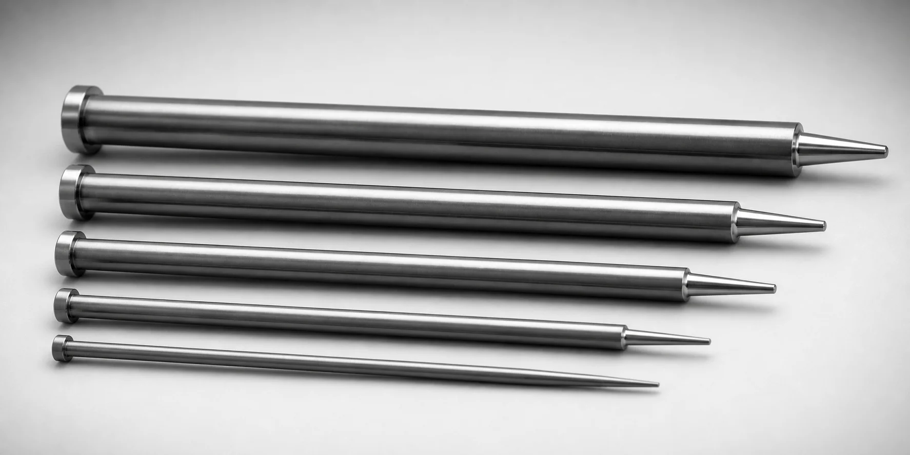
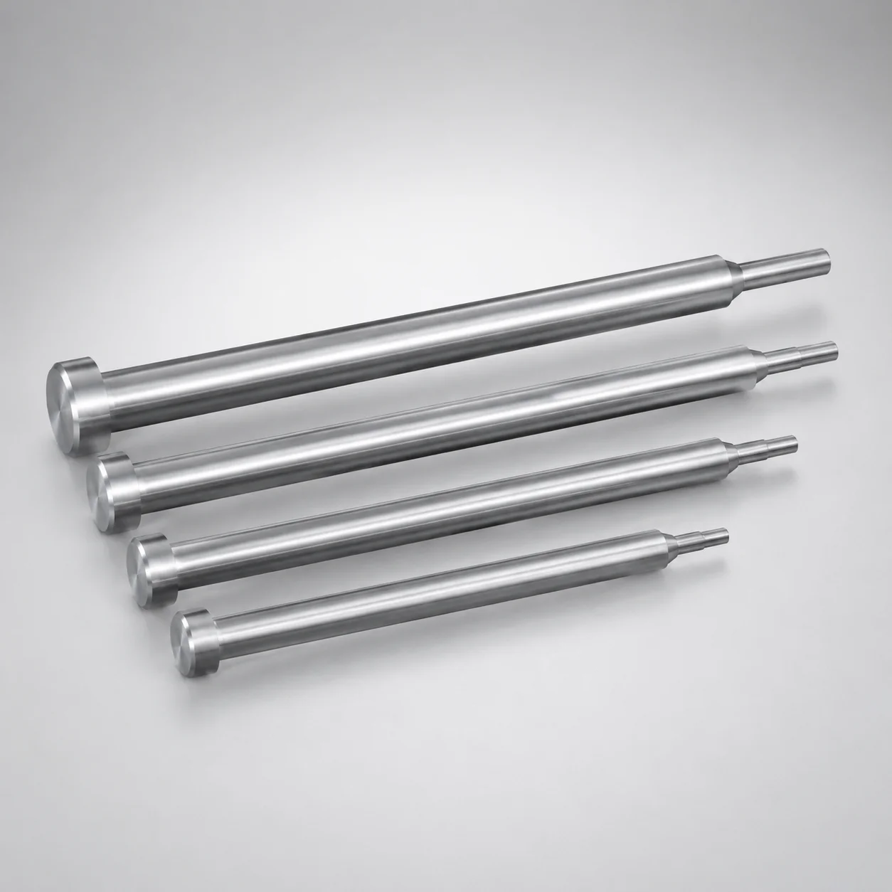
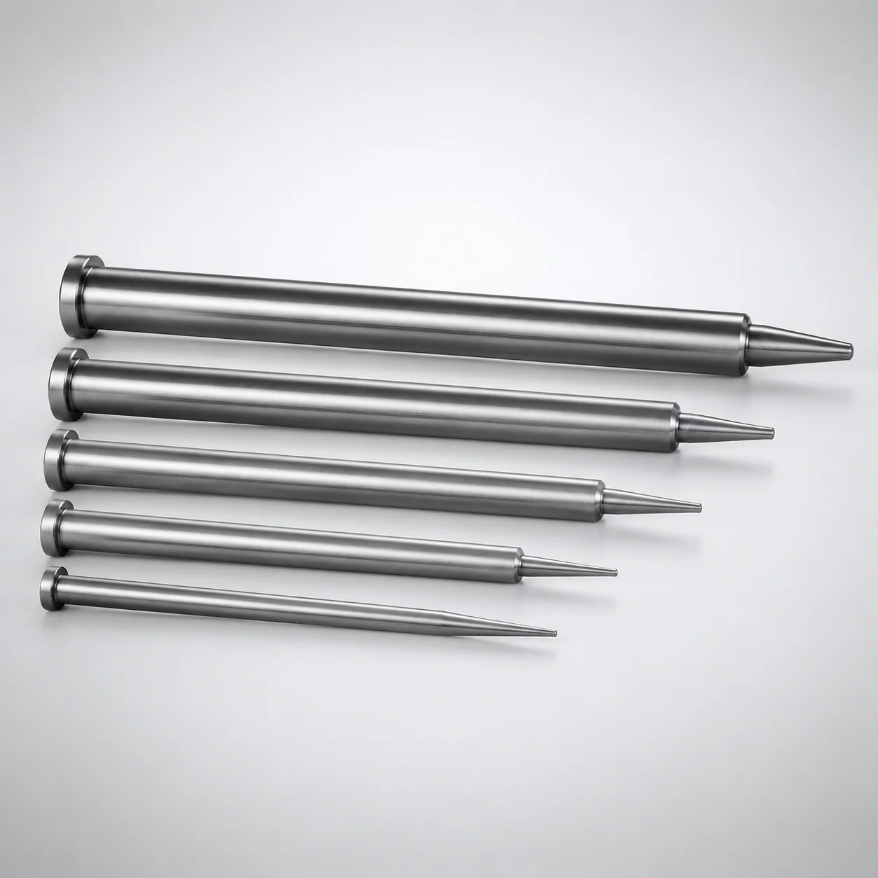
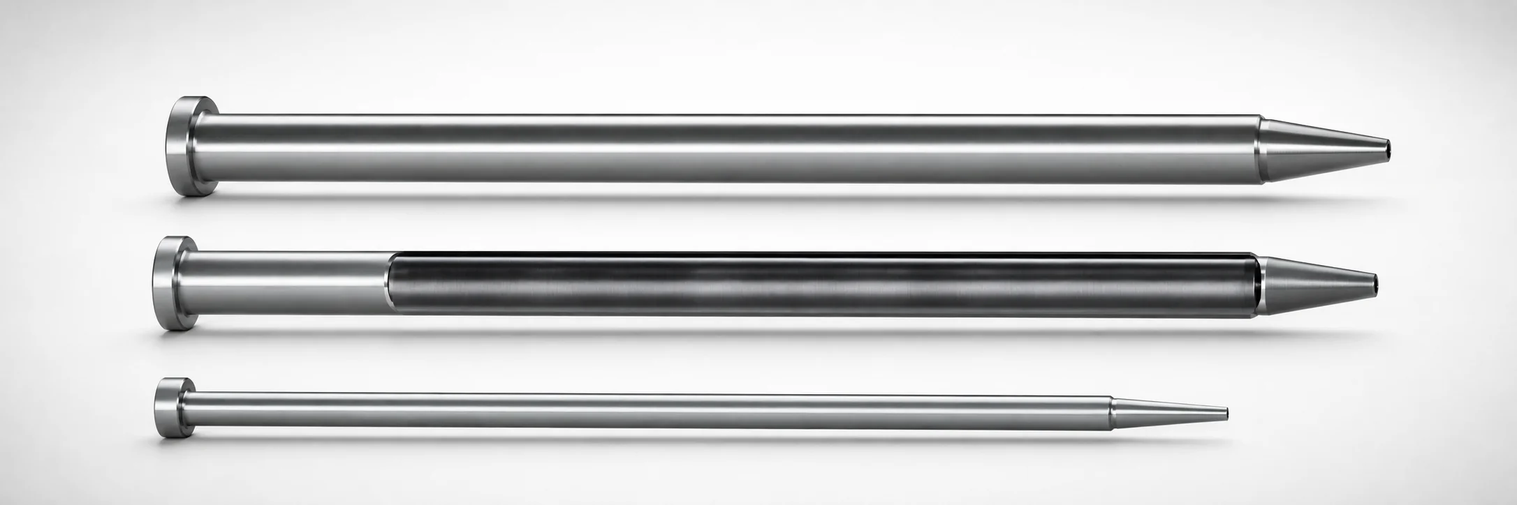
DIN Standard SKD61 Steel One-Step Center Pins (Nitrided)
One-step center pins (SKD61 steel) (nitrided) are designed for reliable positioning in mold and press tool assemblies, combining a one-step locating profile with wear-resistant surface performance for consistent operation.
- One-step geometry supports repeatable sleeve alignment in tooling systems
- Nitrided SKD61 steel improves wear resistance for long cycle life
- Matched shaft diameter tolerance reference (−0.01/−0.02) for stable press-fit
- Compatible sleeve hole fit using H7-reference clearance (+0.01/0)
Specifications
2062 configurations available
| Head Thickness | D/P (Shaft Diameter) (mm) | Step Shape | Tip Shape | A/V (Tip tolerance) | A (Tip part) (mm) | C (Tip part) (mm) | F (Shaft diameter length) (mm) | G (Tip C chamfering width on the tip part) (mm) | K (Tip part angle) (°) | L (L dimension) (mm) | Q (Tip R chamfering on the tip part) (mm) | R (Tip part) (mm) | S (Tip tapered width on the tip part) (mm) | V (Tip diameter in the tip part) (mm) | type |
|---|---|---|---|---|---|---|---|---|---|---|---|---|---|---|---|
| 4mm(JIS) | 1.5 | A | No processing | ±0.02 | - | - | 50 ~ 199.5 | - | - | 70 ~ 200 | - | - | - | 0.5 ~ 1.49 | - |
| 4mm(JIS) | 2 | A | No processing | ±0.02 | - | - | 50 ~ 399.5 | - | - | 70 ~ 400 | - | - | - | 0.7 ~ 1.99 | - |
| 4mm(JIS) | 2.5 | A | No processing | ±0.02 | - | - | 50 ~ 399.5 | - | - | 70 ~ 400 | - | - | - | 0.7 ~ 2.49 | - |
| 4mm(JIS) | 3 | A | No processing | ±0.02 | - | - | 50 ~ 498.5 | - | - | 70 ~ 500 | - | - | - | 1 ~ 2.99 | - |
| 4mm(JIS) | 3.5 | A | No processing | ±0.02 | - | - | 50 ~ 499.5 | - | - | 70 ~ 500 | - | - | - | 1 ~ 3.49 | - |
| 6mm(JIS) | 4 | A | No processing | ±0.02 | - | - | 50 ~ 698.5 | - | - | 70 ~ 700 | - | - | - | 1 ~ 3.99 | - |
| 6mm(JIS) | 4.5 | A | No processing | ±0.02 | - | - | 50 ~ 698.5 | - | - | 70 ~ 700 | - | - | - | 1.5 ~ 4.49 | - |
| 6mm(JIS) | 5 | A | No processing | ±0.02 | - | - | 50 ~ 698.5 | - | - | 70 ~ 700 | - | - | - | 1.5 ~ 4.99 | - |
| 6mm(JIS) | 5.5 | A | No processing | ±0.02 | - | - | 50 ~ 498.5 | - | - | 70 ~ 500 | - | - | - | 2 ~ 5.49 | - |
| 6mm(JIS) | 6 | A | No processing | ±0.02 | - | - | 50 ~ 698.5 | - | - | 70 ~ 700 | - | - | - | 2 ~ 5.99 | - |
| 6mm(JIS) | 6 | A | No processing | ±0.02 | - | - | 50 ~ 698.5 | - | - | 500.1 ~ 700 | - | - | - | 2 ~ 5.99 | - |
| 6mm(JIS) | 6.5 | A | No processing | ±0.02 | - | - | 50 ~ 698.5 | - | - | 70 ~ 700 | - | - | - | 2 ~ 6.49 | - |
| 6mm(JIS) | 6.5 | A | No processing | ±0.02 | - | - | 50 ~ 698.5 | - | - | 500.1 ~ 700 | - | - | - | 2 ~ 6.49 | - |
| 6mm(JIS) | 7 | A | No processing | ±0.02 | - | - | 50 ~ 798.5 | - | - | 70 ~ 800 | - | - | - | 2 ~ 6.99 | - |
| 6mm(JIS) | 7 | A | No processing | ±0.02 | - | - | 50 ~ 798.5 | - | - | 500.1 ~ 800 | - | - | - | 2 ~ 6.99 | - |
| 8mm(JIS) | 8 | A | No processing | ±0.02 | - | - | 50 ~ 799.5 | - | - | 70 ~ 800 | - | - | - | 2 ~ 7.99 | - |
| 8mm(JIS) | 8 | A | No processing | ±0.02 | - | - | 50 ~ 799.5 | - | - | 500.1 ~ 800 | - | - | - | 2 ~ 7.99 | - |
| 8mm(JIS) | 9 | A | No processing | ±0.02 | - | - | 50 ~ 799.5 | - | - | 70 ~ 800 | - | - | - | 2 ~ 8.99 | - |
| 8mm(JIS) | 9 | A | No processing | ±0.02 | - | - | 50 ~ 799.5 | - | - | 500.1 ~ 800 | - | - | - | 2 ~ 8.99 | - |
| 8mm(JIS) | 10 | A | No processing | ±0.02 | - | - | 50 ~ 799.5 | - | - | 70 ~ 800 | - | - | - | 2 ~ 9.99 | - |
| 8mm(JIS) | 10 | A | No processing | ±0.02 | - | - | 50 ~ 799.5 | - | - | 500.1 ~ 800 | - | - | - | 2 ~ 9.99 | - |
| 8mm(JIS) | 12 | A | No processing | ±0.02 | - | - | 50 ~ 799.5 | - | - | 70 ~ 800 | - | - | - | 2 ~ 11.99 | - |
| 8mm(JIS) | 12 | A | No processing | ±0.02 | - | - | 50 ~ 799.5 | - | - | 500.1 ~ 800 | - | - | - | 2 ~ 11.99 | - |
| 8mm(JIS) | 15 | A | No processing | ±0.02 | - | - | 50 ~ 799.5 | - | - | 70 ~ 800 | - | - | - | 2 ~ 14.99 | - |
| 8mm(JIS) | 15 | A | No processing | ±0.02 | - | - | 50 ~ 799.5 | - | - | 500.1 ~ 800 | - | - | - | 2 ~ 14.99 | - |
| 8mm(JIS) | 16 | A | No processing | ±0.02 | - | - | 50 ~ 799.5 | - | - | 70 ~ 800 | - | - | - | 2.5 ~ 15.99 | - |
| 8mm(JIS) | 16 | A | No processing | ±0.02 | - | - | 50 ~ 799.5 | - | - | 500.1 ~ 800 | - | - | - | 2.5 ~ 15.99 | - |
| 4mm(JIS) | 1.5 | A | B | ±0.02 | - | - | 50 ~ 199.5 | - | - | 70 ~ 200 | - | - | - | 0.5 ~ 1.49 | - |
| 4mm(JIS) | 2 | A | B | ±0.02 | - | - | 50 ~ 399.5 | - | - | 70 ~ 400 | - | - | - | 0.7 ~ 1.99 | - |
| 4mm(JIS) | 2.5 | A | B | ±0.02 | - | - | 50 ~ 399.5 | - | - | 70 ~ 400 | - | - | - | 0.7 ~ 2.49 | - |
| 4mm(JIS) | 3 | A | B | ±0.02 | - | - | 50 ~ 499.5 | - | - | 70 ~ 500 | - | - | - | 1 ~ 2.99 | - |
| 4mm(JIS) | 3.5 | A | B | ±0.02 | - | - | 50 ~ 499.5 | - | - | 70 ~ 500 | - | - | - | 1 ~ 3.49 | - |
| 6mm(JIS) | 4 | A | B | ±0.02 | - | - | 50 ~ 699.5 | - | - | 70 ~ 700 | - | - | - | 1 ~ 3.99 | - |
| 6mm(JIS) | 4.5 | A | B | ±0.02 | - | - | 50 ~ 699.5 | - | - | 70 ~ 700 | - | - | - | 1.5 ~ 4.49 | - |
| 6mm(JIS) | 5 | A | B | ±0.02 | - | - | 50 ~ 699.5 | - | - | 70 ~ 700 | - | - | - | 1.5 ~ 4.99 | - |
| 6mm(JIS) | 5.5 | A | B | ±0.02 | - | - | 50 ~ 499.5 | - | - | 70 ~ 500 | - | - | - | 1.5 ~ 5.49 | - |
| 6mm(JIS) | 6 | A | B | ±0.02 | - | - | 50 ~ 699.5 | - | - | 70 ~ 700 | - | - | - | 2 ~ 5.99 | - |
| 6mm(JIS) | 6.5 | A | B | ±0.02 | - | - | 50 ~ 699.5 | - | - | 70 ~ 700 | - | - | - | 2 ~ 6.49 | - |
| 6mm(JIS) | 7 | A | B | ±0.02 | - | - | 50 ~ 799.5 | - | - | 70 ~ 800 | - | - | - | 2 ~ 6.99 | - |
| 8mm(JIS) | 8 | A | B | ±0.02 | - | - | 50 ~ 799.5 | - | - | 70 ~ 800 | - | - | - | 2 ~ 7.99 | - |
| 8mm(JIS) | 9 | A | B | ±0.02 | - | - | 50 ~ 799.5 | - | - | 70 ~ 800 | - | - | - | 2 ~ 8.99 | - |
| 8mm(JIS) | 10 | A | B | ±0.02 | - | - | 50 ~ 799.5 | - | - | 70 ~ 800 | - | - | - | 2 ~ 9.99 | - |
| 8mm(JIS) | 12 | A | B | ±0.02 | - | - | 50 ~ 799.5 | - | - | 70 ~ 800 | - | - | - | 2 ~ 11.99 | - |
| 8mm(JIS) | 15 | A | B | ±0.02 | - | - | 50 ~ 799.5 | - | - | 70 ~ 800 | - | - | - | 2 ~ 11.99 | - |
| 8mm(JIS) | 16 | A | B | ±0.02 | - | - | 50 ~ 799.5 | - | - | 70 ~ 800 | - | - | - | 2 ~ 11.99 | - |
| 4mm(JIS) | 1.5 | A | C | ±0.02 | - | - | 50 ~ 199.5 | 0.5 ~ 0.7 | - | 70 ~ 200 | - | - | - | 0.5 ~ 1.49 | - |
| 4mm(JIS) | 2 | A | C | ±0.02 | - | - | 50 ~ 399.5 | 0.5 ~ 0.9 | - | 70 ~ 400 | - | - | - | 0.7 ~ 1.99 | - |
| 4mm(JIS) | 2.5 | A | C | ±0.02 | - | - | 50 ~ 399.5 | 0.5 ~ 1.2 | - | 70 ~ 400 | - | - | - | 0.7 ~ 2.49 | - |
| 4mm(JIS) | 3 | A | C | ±0.02 | - | - | 50 ~ 499.5 | 0.5 ~ 1.4 | - | 70 ~ 500 | - | - | - | 1 ~ 2.99 | - |
| 4mm(JIS) | 3.5 | A | C | ±0.02 | - | - | 50 ~ 499.5 | 0.5 ~ 1.7 | - | 70 ~ 500 | - | - | - | 1 ~ 3.49 | - |
Product Guide
Application Scenarios+
These one-step center pins are used in injection molding and press-tool assemblies where accurate sleeve-to-sleeve alignment is critical. The one-step profile helps locate mating sleeves in a single engagement, reducing drift during repeated setups and improving repeatability across production runs.
- Automotive connector and sensor housings: In multi-part tooling with stepped ejector sleeves, the nitrided surface on SKD61 supports stable fits under frequent cycling, helping maintain location as cavity pressure and thermal loads fluctuate.
- Medical device housings: For precision alignment in small-cavity molds, the tight shaft fit reference (−0.01/−0.02) supports controlled press-fit seating so the tooling returns consistently after maintenance.
- Industrial caps/closures molds: Where long cycle life and wear resistance are priorities, the nitrided SKD61 finish improves resistance to fretting and micro-wear at the locating interface.
The configured stepped geometry and the specified shaft-to-sleeve fit references make this variant especially suited for applications that demand consistent alignment without frequent rework.
Material & Process Details+
DIN Standard SKD61 (tool steel) is selected for its balance of hardness, wear resistance, and toughness in mold tooling. In this variant, the pins are nitrided to form a hard, wear-resistant surface layer that helps resist galling and fretting at the one-step locating interface.
- Heat treatment state: nitrided SKD61 pins (surface treated for improved wear performance).
- Hardness & wear vs. toughness: nitriding increases surface hardness and wear resistance, while the underlying SKD61 retains core toughness to limit chipping risk during press-fit seating.
- Trade-offs vs. non-nitrided tool steels: nitrided SKD61 generally prioritizes surface durability; compared with through-hardened options, it focuses wear resistance at the surface where contact occurs.
Choose this SKD61 nitrided design when cycle-life and stable locating under repetitive tooling loads are primary requirements.
Sizing & Selection Guide+
Select the pin size by matching the shaft diameter (D/P) and the overall length (L) to your tooling’s core/cavity or sleeve stack-up requirements. Available shaft diameter range is 1.5 ~ 16 mm, and the L dimension ranges from 70 ~ 500.1 mm depending on the selected configuration.
- Match the press-fit: use the provided shaft fit reference of (−0.01/−0.02) for the shaft, and pair it with the sleeve hole fit reference of H7-based clearance (+0.01/0). This is intended to yield a stable press-fit seating without excessive looseness.
- Verify tip geometry for location repeatability: choose the step shape (A/B/C/D/E) and tip shape option (No processing, B, C, G, R, T) that matches the locating pocket profile in your sleeve.
- Confirm tolerances at the tip: tip part tolerance options are ±0.02 or ±0.01, with A (0.5 ~ 2.5 mm) and other tip dimensions (e.g., V 0.5 ~ 2.5 mm) selecting the correct fit/engagement.
Where required, keep the one-step profile aligned with your sleeve hole’s reference to preserve repeatability across assemblies.
Frequently Asked Questions
How do the shaft diameter and sleeve hole fit references work for a stable press-fit?+
The shaft diameter reference is given as (−0.01/−0.02), while the sleeve hole compatibility is specified using an H7-reference clearance (+0.01/0). This pairing is intended to support a controlled press-fit for repeatable positioning.
When sizing, ensure your sleeve hole is dimensioned to H7-based reference so the clearance window matches the pin’s shaft tolerance behavior.
Which length range should I select for ejector/sleeve stacks, and how does L affect engagement?+
The available L dimension range is 70 ~ 500.1 mm. Choose L so the pin provides sufficient engagement through the sleeve/tool stack to achieve consistent locating at the one-step profile.
If your stack height varies after maintenance or re-grinding, re-check L against the current sleeve/core assembly dimensions.
What does the one-step geometry change compared with non-stepped locating pins?+
The one-step profile is designed to provide stable, repeatable location in a single engagement. Instead of relying solely on a straight cylindrical fit, the stepped profile guides the sleeve alignment to reduce positional drift during repeated cycles.
Select the appropriate step shape (A/B/C/D/E) to match the pocket geometry in your sleeve.
Why choose nitrided SKD61 for center pins in high-cycle molds?+
This variant uses DIN Standard SKD61 steel with a nitrided surface to improve wear performance at the contacting locating interface. The nitrided layer increases surface durability, helping resist fretting/micro-wear during frequent tooling operation.
The core SKD61 still provides toughness to reduce the risk of damage during press-fit seating.
How do tip tolerance and tip dimensions (A/V) affect precision for small tooling?+
Tip tolerance is available as ±0.02 or ±0.01, and the tip part dimensions include A (0.5 ~ 2.5 mm) and V (0.5 ~ 2.5 mm). For precision cavities, use the tighter tolerance option (±0.01) when your sleeve locating pocket is also dimensionally controlled.
Confirm the chosen tip shape and chamfering parameters (e.g., G 0.1 ~ 0.5 mm) align with the mating feature’s geometry.
Related Products
Need Custom Specifications?
Our engineering team can help with custom configurations, material selection, and volume pricing.