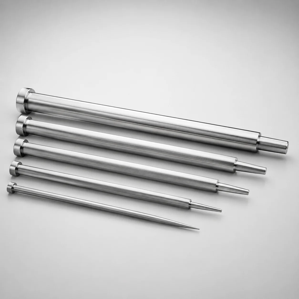
JIS Standard M2 Steel One-Step Center Pins
One-Step center pins (M2 steel) are designed for reliable mold centering in precision tooling. The one-step geometry helps maintain repeatable alignment during setup and production cycles.
- One-step pin design for stable center positioning and consistent assembly
- SKH51 steel construction with hardened performance for wear-resistant operation
- Shaft diameter tolerance supports tight sleeve-hole fit for accurate seating
- Compatible with JIS-style mold components for long-term tooling repeatability
Specifications
3025 configurations available
| Head Thickness | D/P (Shaft Diameter) (mm) | Step Shape | Tip Shape | A/V (Tip tolerance) | A (Tip part) (mm) | C (Tip part) (mm) | F (Shaft diameter length) (mm) | G (Tip C chamfering width on the tip part) (mm) | K (Tip part angle) (°) | L (L dimension) (mm) | Q (Tip R chamfering on the tip part) (mm) | R (Tip part) (mm) | S (Tip tapered width on the tip part) (mm) | V (Tip diameter in the tip part) (mm) | type |
|---|---|---|---|---|---|---|---|---|---|---|---|---|---|---|---|
| 4mm(T4) | 1 | A | No processing | ±0.01 | - | - | 50 ~ 199.5 | - | - | 70 ~ 200 | - | - | - | 0.5 ~ 0.99 | - |
| 4mm(T4) | 1.5 | A | No processing | ±0.01 | - | - | 50 ~ 249.5 | - | - | 70 ~ 250 | - | - | - | 0.5 ~ 1.49 | - |
| 4mm(T4) | 2 | A | No processing | ±0.01 | - | - | 50 ~ 249.5 | - | - | 70 ~ 250 | - | - | - | 0.7 ~ 1.99 | - |
| 4mm(T4) | 2.5 | A | No processing | ±0.01 | - | - | 50 ~ 249.5 | - | - | 70 ~ 250 | - | - | - | 0.7 ~ 2.49 | - |
| 4mm(T4) | 3 | A | No processing | ±0.01 | - | - | 50 ~ 299.5 | - | - | 70 ~ 300 | - | - | - | 1 ~ 2.99 | - |
| 4mm(T4) | 3.5 | A | No processing | ±0.01 | - | - | 50 ~ 299.5 | - | - | 70 ~ 300 | - | - | - | 1 ~ 3.49 | - |
| 4mm(T4) | 4 | A | No processing | ±0.01 | - | - | 50 ~ 299.5 | - | - | 70 ~ 300 | - | - | - | 1 ~ 3.99 | - |
| 4mm(T4) | 4.5 | A | No processing | ±0.01 | - | - | 50 ~ 295.5 | - | - | 70 ~ 300 | - | - | - | 1.5 ~ 4.49 | - |
| 4mm(T4) | 5 | A | No processing | ±0.01 | - | - | 50 ~ 349.5 | - | - | 70 ~ 350 | - | - | - | 1.5 ~ 4.99 | - |
| 4mm(T4) | 5.5 | A | No processing | ±0.01 | - | - | 50 ~ 349.5 | - | - | 70 ~ 350 | - | - | - | 2 ~ 5.49 | - |
| 4mm(T4) | 6 | A | No processing | ±0.01 | - | - | 50 ~ 349.5 | - | - | 70 ~ 350 | - | - | - | 2 ~ 5.99 | - |
| 4mm(T4) | 6.5 | A | No processing | ±0.01 | - | - | 50 ~ 349.5 | - | - | 70 ~ 350 | - | - | - | 2 ~ 6.49 | - |
| 4mm(T4) | 7 | A | No processing | ±0.01 | - | - | 50 ~ 349.5 | - | - | 70 ~ 350 | - | - | - | 2 ~ 6.99 | - |
| 4mm(T4) | 8 | A | No processing | ±0.01 | - | - | 50 ~ 349.5 | - | - | 70 ~ 350 | - | - | - | 2 ~ 7.99 | - |
| 4mm(T4) | 9 | A | No processing | ±0.01 | - | - | 50 ~ 349.5 | - | - | 70 ~ 350 | - | - | - | 2 ~ 8.99 | - |
| 4mm(T4) | 10 | A | No processing | ±0.01 | - | - | 50 ~ 349.5 | - | - | 100 ~ 350 | - | - | - | 2 ~ 9.99 | - |
| 4mm(T4) | 12 | A | No processing | ±0.01 | - | - | 50 ~ 349.5 | - | - | 100 ~ 350 | - | - | - | 2 ~ 11.99 | - |
| 4mm(T4) | 1 | A | B | ±0.01 | - | - | 50 ~ 199.5 | - | - | 70 ~ 200 | - | - | - | 0.5 ~ 0.99 | - |
| 4mm(T4) | 1.5 | A | B | ±0.01 | - | - | 50 ~ 249.5 | - | - | 70 ~ 250 | - | - | - | 0.5 ~ 1.49 | - |
| 4mm(T4) | 2 | A | B | ±0.01 | - | - | 50 ~ 249.5 | - | - | 70 ~ 250 | - | - | - | 0.7 ~ 1.99 | - |
| 4mm(T4) | 2.5 | A | B | ±0.01 | - | - | 50 ~ 249.5 | - | - | 70 ~ 250 | - | - | - | 0.7 ~ 2.49 | - |
| 4mm(T4) | 3 | A | B | ±0.01 | - | - | 50 ~ 299.5 | - | - | 70 ~ 300 | - | - | - | 1 ~ 2.99 | - |
| 4mm(T4) | 3.5 | A | B | ±0.01 | - | - | 50 ~ 299.5 | - | - | 70 ~ 300 | - | - | - | 1 ~ 3.49 | - |
| 4mm(T4) | 4 | A | B | ±0.01 | - | - | 50 ~ 299.5 | - | - | 70 ~ 300 | - | - | - | 1 ~ 3.99 | - |
| 4mm(T4) | 4.5 | A | B | ±0.01 | - | - | 50 ~ 299.5 | - | - | 70 ~ 300 | - | - | - | 1.5 ~ 4.49 | - |
| 4mm(T4) | 5 | A | B | ±0.01 | - | - | 50 ~ 349.5 | - | - | 70 ~ 350 | - | - | - | 1.5 ~ 4.99 | - |
| 4mm(T4) | 5.5 | A | B | ±0.01 | - | - | 50 ~ 349.5 | - | - | 70 ~ 350 | - | - | - | 1.5 ~ 5.49 | - |
| 4mm(T4) | 6 | A | B | ±0.01 | - | - | 50 ~ 349.5 | - | - | 70 ~ 350 | - | - | - | 2 ~ 5.99 | - |
| 4mm(T4) | 6.5 | A | B | ±0.01 | - | - | 50 ~ 349.5 | - | - | 70 ~ 350 | - | - | - | 2 ~ 6.49 | - |
| 4mm(T4) | 7 | A | B | ±0.01 | - | - | 50 ~ 349.5 | - | - | 70 ~ 350 | - | - | - | 2 ~ 6.99 | - |
| 4mm(T4) | 8 | A | B | ±0.01 | - | - | 50 ~ 349.5 | - | - | 70 ~ 350 | - | - | - | 2 ~ 7.99 | - |
| 4mm(T4) | 9 | A | B | ±0.01 | - | - | 50 ~ 349.5 | - | - | 70 ~ 350 | - | - | - | 2 ~ 8.99 | - |
| 4mm(T4) | 10 | A | B | ±0.01 | - | - | 50 ~ 349.5 | - | - | 70 ~ 350 | - | - | - | 2 ~ 9.99 | - |
| 4mm(T4) | 12 | A | B | ±0.01 | - | - | 50 ~ 349.5 | - | - | 70 ~ 350 | - | - | - | 2 ~ 11.99 | - |
| 4mm(T4) | 1 | A | C | ±0.01 | - | - | 50 ~ 199.5 | 0.3 ~ 0.4 | - | 70 ~ 200 | - | - | - | 0.5 ~ 0.99 | - |
| 4mm(T4) | 1.5 | A | C | ±0.01 | - | - | 50 ~ 249.5 | 0.5 ~ 0.7 | - | 70 ~ 250 | - | - | - | 0.5 ~ 1.49 | - |
| 4mm(T4) | 2 | A | C | ±0.01 | - | - | 50 ~ 249.5 | 0.5 ~ 0.9 | - | 70 ~ 250 | - | - | - | 0.7 ~ 1.99 | - |
| 4mm(T4) | 2.5 | A | C | ±0.01 | - | - | 50 ~ 249.5 | 0.5 ~ 1.2 | - | 70 ~ 250 | - | - | - | 0.7 ~ 2.49 | - |
| 4mm(T4) | 3 | A | C | ±0.01 | - | - | 50 ~ 299.5 | 0.5 ~ 1.4 | - | 70 ~ 300 | - | - | - | 1 ~ 2.99 | - |
| 4mm(T4) | 3.5 | A | C | ±0.01 | - | - | 50 ~ 299.5 | 0.5 ~ 1.7 | - | 70 ~ 300 | - | - | - | 1 ~ 3.49 | - |
| 4mm(T4) | 4 | A | C | ±0.01 | - | - | 50 ~ 299.5 | 0.5 ~ 1.9 | - | 70 ~ 300 | - | - | - | 1 ~ 3.99 | - |
| 4mm(T4) | 4.5 | A | C | ±0.01 | - | - | 50 ~ 299.5 | 0.5 ~ 2.2 | - | 70 ~ 300 | - | - | - | 1.5 ~ 4.49 | - |
| 4mm(T4) | 5 | A | C | ±0.01 | - | - | 50 ~ 349.5 | 0.5 ~ 2.4 | - | 70 ~ 350 | - | - | - | 1.5 ~ 4.99 | - |
| 4mm(T4) | 5.5 | A | C | ±0.01 | - | - | 50 ~ 349.5 | 0.5 ~ 2.7 | - | 70 ~ 350 | - | - | - | 1.5 ~ 5.49 | - |
| 4mm(T4) | 6 | A | C | ±0.01 | - | - | 50 ~ 349.5 | 0.5 ~ 2.9 | - | 70 ~ 350 | - | - | - | 2 ~ 5.99 | - |
| 4mm(T4) | 6.5 | A | C | ±0.01 | - | - | 50 ~ 349.5 | 0.5 ~ 3.2 | - | 70 ~ 350 | - | - | - | 2 ~ 6.49 | - |
| 4mm(T4) | 7 | A | C | ±0.01 | - | - | 50 ~ 349.5 | 0.5 ~ 3.4 | - | 70 ~ 350 | - | - | - | 2 ~ 6.99 | - |
| 4mm(T4) | 8 | A | C | ±0.01 | - | - | 50 ~ 349.5 | 0.5 ~ 3.9 | - | 70 ~ 350 | - | - | - | 2 ~ 7.99 | - |
| 4mm(T4) | 9 | A | C | ±0.01 | - | - | 50 ~ 349.5 | 0.5 ~ 4.9 | - | 70 ~ 350 | - | - | - | 2 ~ 8.99 | - |
| 4mm(T4) | 10 | A | C | ±0.01 | - | - | 50 ~ 349.5 | 0.5 ~ 4.9 | - | 70 ~ 350 | - | - | - | 2 ~ 9.99 | - |
Product Guide
Application Scenarios+
These one-step center pins are used in injection mold assembly to maintain precise alignment between stationary and moving components. The one-step geometry provides a repeatable seating location during setup, reducing shift risk across production cycles.
- Automotive connector and insert molds: Install in JIS-style alignment zones where consistent centering helps prevent parting-line mismatch and improves cavity repeatability. The SKH51-hardened, wear-resistant performance supports long-running tool operation.
- Electronics and housings with tight concentricity: Use the stepped tip and controlled shaft diameter to guide sleeve-hole engagement, supporting stable alignment for thin-wall or high-feature count parts.
- Medical device housings and precision overmolding tools: The tight tip tolerances (e.g., A/V: ±0.005 to ±0.02) help achieve accurate positioning, which is critical for dimensional stability and downstream assembly fit.
Choose the step shape (A–E) and tip processing option to match your sleeve interface and required centering profile.
Material & Process Details+
This variant is made from JIS M2 steel (SKH51), selected for hardened wear performance in centering features. SKH51 is commonly treated as an AISI M2 (high-speed steel) equivalent used where sliding contact and alignment stability are required.
- Heat treatment: Supplied as a hardened performance configuration appropriate for repeated tool cycles (exact HRC value is not provided in the supplied data).
- Hardness & wear: M2/SKH51 grades are engineered for high wear resistance; this supports stable pin/sleeve engagement under normal mold assembly friction.
- Toughness trade-off: Higher hardness improves wear resistance, but can reduce toughness compared with lower-alloy steels—making geometry and proper seating contact important.
If alternative steel options are offered for the same geometry, compare based on required wear life versus impact/toughness needs; for most alignment pins, SKH51-hardened performance prioritizes dimensional retention.
Sizing & Selection Guide+
Correct sizing starts with matching the shaft diameter (D/P: 1–12 mm) to your alignment sleeve or guide hole. Then select the one-step geometry and tip processing that match the intended seating behavior.
- Shaft diameter fit: Use the specified D/P value so the pin engages the sleeve-hole interface with the intended tightness. For best repeatability, keep shaft-to-sleeve clearance within your mold design tolerance targets.
- Tip and centering accuracy: Choose A/V (tip tolerance: ±0.005, ±0.01, ±0.02) based on your centering sensitivity. Smaller tolerance (e.g., ±0.005) supports higher precision alignment.
- Length matching: Confirm overall L (70–350 mm) selection range against the required mold thickness stack. Also verify shaft diameter length F (50 mm) to ensure the engagement zone is sufficient for your sleeve depth.
- Geometry selection: Select step shape (A–E) and tip shape (No processing, B, C, G, R, T) so the step chamfers (e.g., Q 0.2) and tip dimensions (A: 0.5–2 mm, V: 0.5–2 mm) align with the mating part profile.
Tolerances are configurable via the provided tip tolerance options; other key dimensions (like F = 50 mm) are fixed per the specification.
Frequently Asked Questions
Which shaft diameter (D/P) range is available for the JIS M2 one-step center pin, and how do I choose it for my sleeve-hole interface?+
What tip tolerance options (A/V) are offered, and how does this affect centering accuracy?+
How do I select the correct L length for the one-step center pin in my mold thickness stack?+
What step and tip geometry choices are available, and which should I consider for sleeve seating stability?+
Is this pin hardened, and what material grade is it based on for wear resistance?+
Related Products
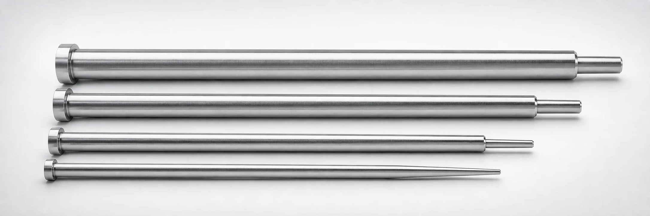
JIS Standard M2 Steel One-Step Center Pins Flat-Sided
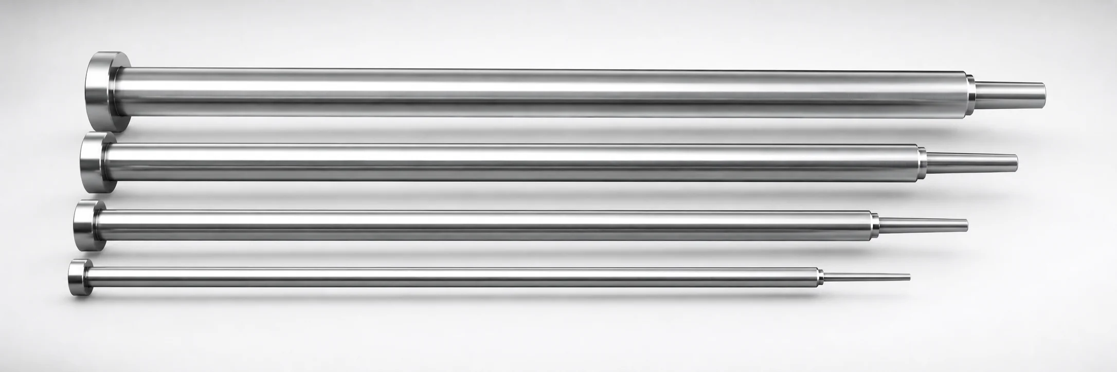
JIS Standard SKH51 Steel One-Step Center Pins
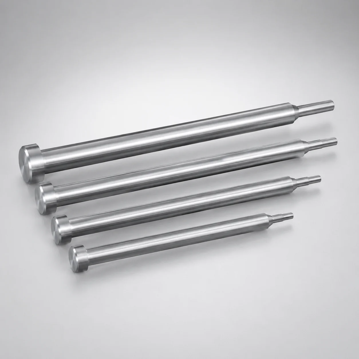
SKH51 Steel One-Step Center Pins
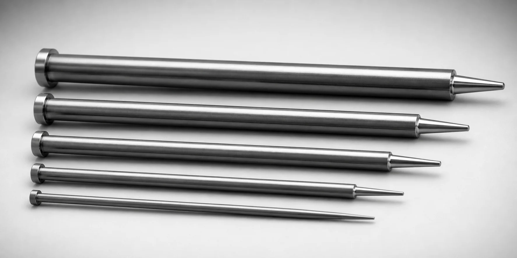
DIN Standard SKD61 Steel One-Step Center Pins (Nitrided)
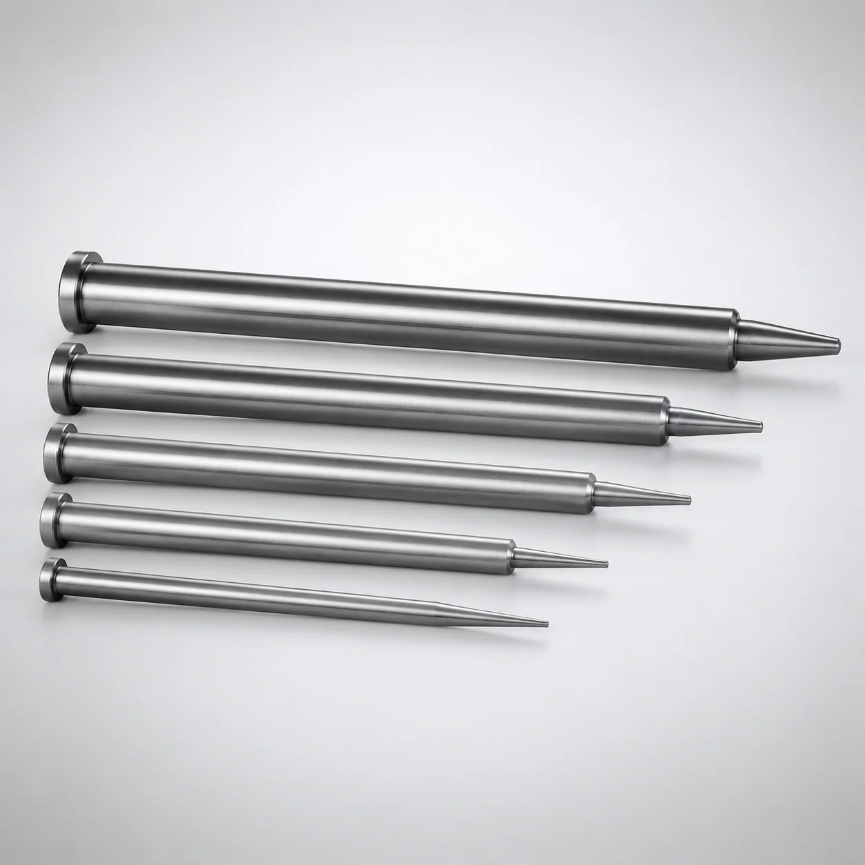
DIN Standard SKD61 Steel One-Step Center Pins Flat-Sided, Nitrided
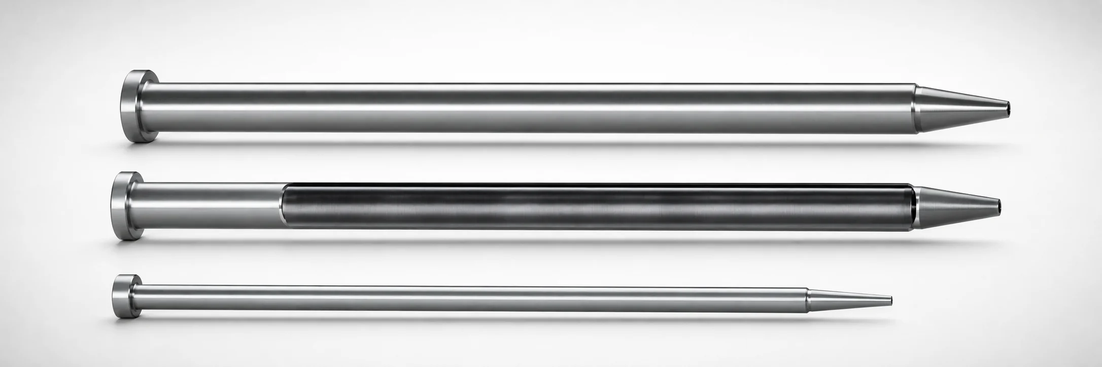
SKD61 Steel One-Step Center Pins with Cooling Hole
Need Custom Specifications?
Our engineering team can help with custom configurations, material selection, and volume pricing.