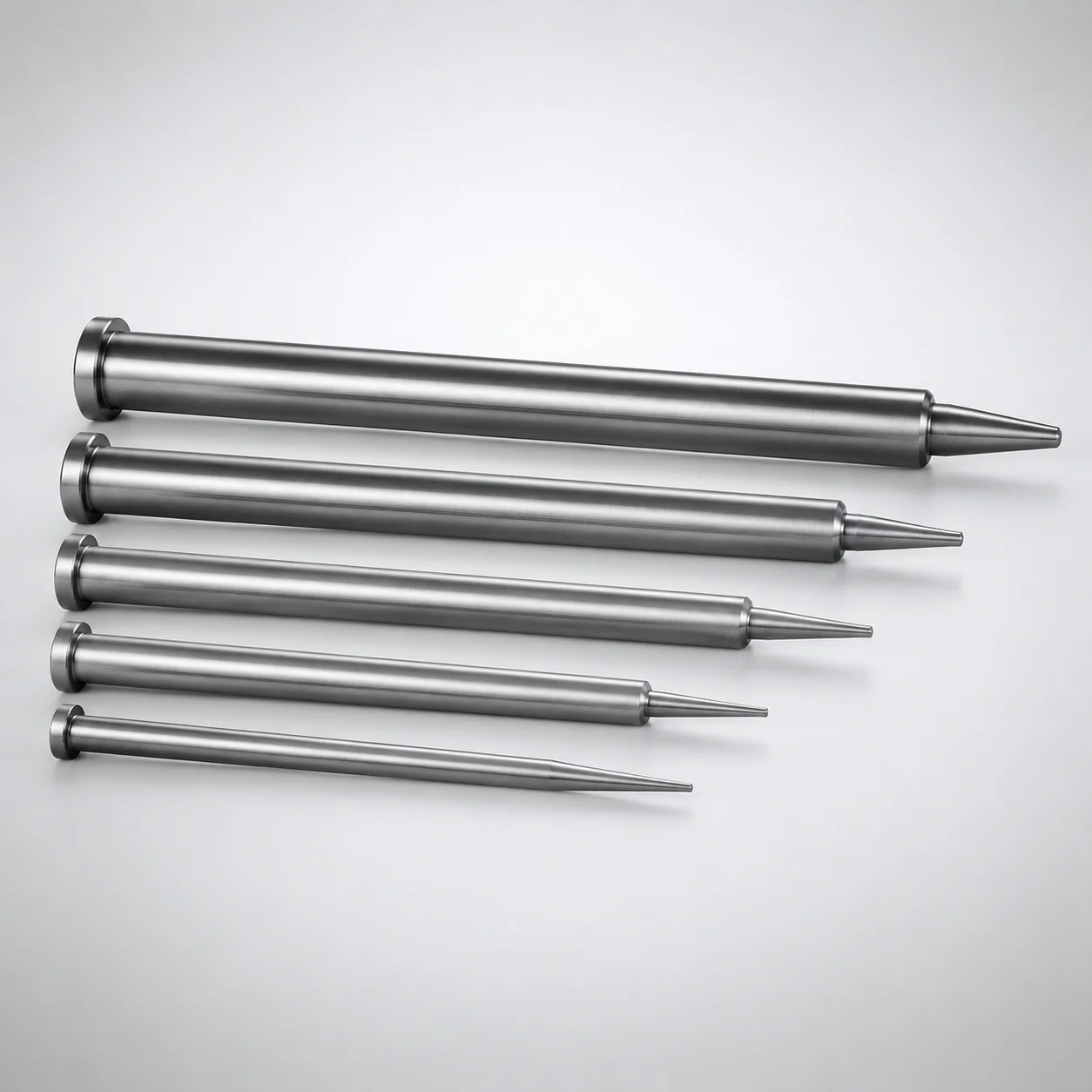
DIN Standard SKD61 Steel One-Step Center Pins Flat-Sided, Nitrided
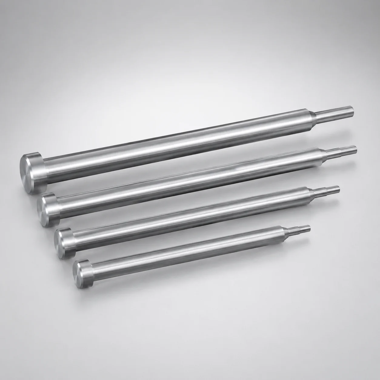
One-step center pins (SKD61 steel) with a nitrided surface provide reliable locating support for press and mold assemblies, helping maintain concentric alignment through repeated cycles.
- Flat-sided one-step head improves anti-rotation positioning for consistent center alignment
- Nitrided SKD61 steel delivers wear resistance for long service life under molding loads
- Reference shaft diameter tolerances and H7 sleeve-hole fit support accurate press-fit assembly
- Built for die and mold work where one-step center pin geometry simplifies setup
Specifications
2875 configurations available
| Head Thickness | D/P (Shaft Diameter) (mm) | Step Shape | Tip Shape | A/V (Tip tolerance) | No. (Nominal diameter) (mm) | A (Tip part) (mm) | C (Tip part) (mm) | F (Shaft diameter length) (mm) | G (Tip C chamfering width on the tip part) (mm) | K (Tip part angle) (°) | L (L dimension) (mm) | Q (Tip R chamfering on the tip part) (mm) | R (Tip part) (mm) | S (Tip tapered width on the tip part) (mm) | V (Tip diameter in the tip part) (mm) | type |
|---|---|---|---|---|---|---|---|---|---|---|---|---|---|---|---|---|
| 4mm(JIS) | 1.5 ~ 1.9 | A | No processing | ±0.02 | 2 | - | - | 50 ~ 299.5 | - | - | 70 ~ 400 | - | - | - | 0.7 ~ 1.9 | - |
| 4mm(JIS) | 2 ~ 2.4 | A | No processing | ±0.02 | 2.5 | - | - | 50 ~ 399.5 | - | - | 70 ~ 400 | - | - | - | 0.7 ~ 2.4 | - |
| 4mm(JIS) | 2.5 ~ 2.9 | A | No processing | ±0.02 | 3 | - | - | 50 ~ 399.5 | - | - | 70 ~ 400 | - | - | - | 1 ~ 2.9 | - |
| 4mm(JIS) | 3 ~ 3.4 | A | No processing | ±0.02 | 3.5 | - | - | 50 ~ 399.5 | - | - | 70 ~ 400 | - | - | - | 1 ~ 3.4 | - |
| 6mm(JIS) | 3.5 ~ 3.9 | A | No processing | ±0.02 | 4 | - | - | 50 ~ 399.5 | - | - | 70 ~ 400 | - | - | - | 1 ~ 3.9 | - |
| 6mm(JIS) | 4 ~ 4.4 | A | No processing | ±0.02 | 4.5 | - | - | 50 ~ 399.5 | - | - | 70 ~ 400 | - | - | - | 1.5 ~ 4.4 | - |
| 6mm(JIS) | 4.5 ~ 4.9 | A | No processing | ±0.02 | 5 | - | - | 50 ~ 499.5 | - | - | 70 ~ 500 | - | - | - | 1.5 ~ 4.9 | - |
| 6mm(JIS) | 5 ~ 5.4 | A | No processing | ±0.02 | 5.5 | - | - | 50 ~ 499.5 | - | - | 70 ~ 500 | - | - | - | 2 ~ 5.4 | - |
| 6mm(JIS) | 5.5 ~ 5.9 | A | No processing | ±0.02 | 6 | - | - | 50 ~ 499.5 | - | - | 70 ~ 500 | - | - | - | 2 ~ 5.9 | - |
| 6mm(JIS) | 6 ~ 6.4 | A | No processing | ±0.02 | 6.5 | - | - | 50 ~ 499.5 | - | - | 70 ~ 500 | - | - | - | 2 ~ 6.4 | - |
| 6mm(JIS) | 6.5 ~ 6.9 | A | No processing | ±0.02 | 7 | - | - | 50 ~ 499.5 | - | - | 70 ~ 500 | - | - | - | 2 ~ 6.9 | - |
| 8mm(JIS) | 7 ~ 7.9 | A | No processing | ±0.02 | 8 | - | - | 50 ~ 499.5 | - | - | 70 ~ 500 | - | - | - | 2 ~ 7.9 | - |
| 8mm(JIS) | 8 ~ 9.9 | A | No processing | ±0.02 | 10 | - | - | 50 ~ 499.5 | - | - | 70 ~ 500 | - | - | - | 2 ~ 9.9 | - |
| 8mm(JIS) | 10 ~ 11.9 | A | No processing | ±0.02 | 12 | - | - | 50 ~ 499.5 | - | - | 70 ~ 500 | - | - | - | 2 ~ 11.9 | - |
| 8mm(JIS) | 12 ~ 14.9 | A | No processing | ±0.02 | 15 | - | - | 50 ~ 499.5 | - | - | 70 ~ 500 | - | - | - | 2 ~ 14.9 | - |
| 8mm(JIS) | 15 ~ 15.9 | A | No processing | ±0.02 | 16 | - | - | 50 ~ 499.5 | - | - | 70 ~ 500 | - | - | - | 2.5 ~ 15.9 | - |
| 4mm(JIS) | 1.5 ~ 1.9 | A | B | ±0.02 | 2 | - | - | 50 ~ 399.5 | - | - | 70 ~ 400 | - | - | - | 0.7 ~ 1.99 | - |
| 4mm(JIS) | 1.5 ~ 1.99 | A | B | ±0.02 | 2 | - | - | 50 ~ 399.5 | - | - | 70 ~ 400 | - | - | - | 0.7 ~ 1.99 | - |
| 4mm(JIS) | 2 ~ 2.4 | A | B | ±0.02 | 2.5 | - | - | 50 ~ 399.5 | - | - | 70 ~ 400 | - | - | - | 0.7 ~ 2.49 | - |
| 4mm(JIS) | 2 ~ 2.49 | A | B | ±0.02 | 2.5 | - | - | 50 ~ 399.5 | - | - | 70 ~ 400 | - | - | - | 0.7 ~ 2.49 | - |
| 4mm(JIS) | 2.5 ~ 2.9 | A | B | ±0.02 | 3 | - | - | 50 ~ 499.5 | - | - | 70 ~ 500 | - | - | - | 1 ~ 2.99 | - |
| 4mm(JIS) | 2.5 ~ 2.99 | A | B | ±0.02 | 3 | - | - | 50 ~ 499.5 | - | - | 70 ~ 500 | - | - | - | 1 ~ 2.99 | - |
| 4mm(JIS) | 3 ~ 3.4 | A | B | ±0.02 | 3.5 | - | - | 50 ~ 499.5 | - | - | 70 ~ 500 | - | - | - | 1 ~ 3.49 | - |
| 4mm(JIS) | 3 ~ 3.49 | A | B | ±0.02 | 3.5 | - | - | 50 ~ 499.5 | - | - | 70 ~ 500 | - | - | - | 1 ~ 3.49 | - |
| 6mm(JIS) | 3.5 ~ 3.9 | A | B | ±0.02 | 4 | - | - | 50 ~ 499.5 | - | - | 70 ~ 500 | - | - | - | 1 ~ 3.99 | - |
| 6mm(JIS) | 3.5 ~ 3.99 | A | B | ±0.02 | 4 | - | - | 50 ~ 499.5 | - | - | 70 ~ 500 | - | - | - | 1 ~ 3.99 | - |
| 6mm(JIS) | 4 ~ 4.4 | A | B | ±0.02 | 4.5 | - | - | 50 ~ 499.5 | - | - | 70 ~ 500 | - | - | - | 1.5 ~ 4.49 | - |
| 6mm(JIS) | 4 ~ 4.49 | A | B | ±0.02 | 4.5 | - | - | 50 ~ 499.5 | - | - | 70 ~ 500 | - | - | - | 1.5 ~ 4.49 | - |
| 6mm(JIS) | 4.5 ~ 4.9 | A | B | ±0.02 | 5 | - | - | 50 ~ 499.5 | - | - | 70 ~ 500 | - | - | - | 1.5 ~ 4.99 | - |
| 6mm(JIS) | 4.5 ~ 4.99 | A | B | ±0.02 | 5 | - | - | 50 ~ 499.5 | - | - | 70 ~ 500 | - | - | - | 1.5 ~ 4.99 | - |
| 6mm(JIS) | 5 ~ 5.49 | A | B | ±0.02 | 5.5 | - | - | 50 ~ 499.5 | - | - | 70 ~ 500 | - | - | - | 1.5 ~ 5.49 | - |
| 6mm(JIS) | 5.5 ~ 5.9 | A | B | ±0.02 | 6 | - | - | 50 ~ 599.5 | - | - | 70 ~ 600 | - | - | - | 2 ~ 5.99 | - |
| 6mm(JIS) | 5.5 ~ 5.99 | A | B | ±0.02 | 6 | - | - | 50 ~ 599.5 | - | - | 70 ~ 600 | - | - | - | 2 ~ 5.99 | - |
| 6mm(JIS) | 6 ~ 6.4 | A | B | ±0.02 | 6.5 | - | - | 50 ~ 599.5 | - | - | 70 ~ 600 | - | - | - | 2 ~ 6.49 | - |
| 6mm(JIS) | 6 ~ 6.49 | A | B | ±0.02 | 6.5 | - | - | 50 ~ 599.5 | - | - | 70 ~ 600 | - | - | - | 2 ~ 6.49 | - |
| 6mm(JIS) | 6.5 ~ 6.9 | A | B | ±0.02 | 7 | - | - | 50 ~ 599.5 | - | - | 70 ~ 600 | - | - | - | 2 ~ 6.99 | - |
| 6mm(JIS) | 6.5 ~ 6.99 | A | B | ±0.02 | 7 | - | - | 50 ~ 599.5 | - | - | 70 ~ 600 | - | - | - | 2 ~ 6.99 | - |
| 8mm(JIS) | 7 ~ 7.9 | A | B | ±0.02 | 8 | - | - | 50 ~ 599.5 | - | - | 70 ~ 600 | - | - | - | 2 ~ 7.99 | - |
| 8mm(JIS) | 7 ~ 7.99 | A | B | ±0.02 | 8 | - | - | 50 ~ 599.5 | - | - | 70 ~ 600 | - | - | - | 2 ~ 7.99 | - |
| 8mm(JIS) | 8 ~ 9.9 | A | B | ±0.02 | 10 | - | - | 50 ~ 599.5 | - | - | 70 ~ 600 | - | - | - | 2 ~ 9.99 | - |
| 8mm(JIS) | 8 ~ 9.99 | A | B | ±0.02 | 10 | - | - | 50 ~ 599.5 | - | - | 70 ~ 600 | - | - | - | 2 ~ 9.99 | - |
| 8mm(JIS) | 10 ~ 11.9 | A | B | ±0.02 | 12 | - | - | 50 ~ 699.5 | - | - | 70 ~ 700 | - | - | - | 2 ~ 11.99 | - |
| 8mm(JIS) | 10 ~ 11.99 | A | B | ±0.02 | 12 | - | - | 50 ~ 699.5 | - | - | 70 ~ 700 | - | - | - | 2 ~ 11.99 | - |
| 8mm(JIS) | 10 ~ 14.99 | A | B | ±0.02 | 15 | - | - | 50 ~ 699.5 | - | - | 70 ~ 700 | - | - | - | 2 ~ 14.99 | - |
| 8mm(JIS) | 12 ~ 14.9 | A | B | ±0.02 | 15 | - | - | 50 ~ 699.5 | - | - | 70 ~ 700 | - | - | - | 2 ~ 14.99 | - |
| 8mm(JIS) | 10 ~ 15.99 | A | B | ±0.02 | 16 | - | - | 50 ~ 699.5 | - | - | 70 ~ 700 | - | - | - | 2 ~ 15.99 | - |
| 8mm(JIS) | 15 ~ 15.9 | A | B | ±0.02 | 16 | - | - | 50 ~ 699.5 | - | - | 70 ~ 700 | - | - | - | 2 ~ 15.99 | - |
| 4mm(JIS) | 1.5 ~ 1.9 | A | C | ±0.02 | 2 | - | - | 50 ~ 399.5 | 0.5 ~ 0.9 | - | 70 ~ 400 | - | - | - | 0.7 ~ 1.99 | - |
| 4mm(JIS) | 1.5 ~ 1.99 | A | C | ±0.02 | 2 | - | - | 50 ~ 399.5 | 0.5 ~ 0.9 | - | 70 ~ 400 | - | - | - | 0.7 ~ 1.99 | - |
| 4mm(JIS) | 2 ~ 2.4 | A | C | ±0.02 | 2.5 | - | - | 50 ~ 399.5 | 0.5 ~ 1.2 | - | 70 ~ 400 | - | - | - | 0.7 ~ 2.49 | - |
Product Guide
Application Scenarios+
One-step center pins with a nitrided SKD61 surface are used to provide stable locating and repeatable concentric alignment in injection mold and press tooling assemblies. Their flat-sided one-step head helps resist rotation during installation and ongoing clamp cycles, which is important when dies must remain centered over repeated production runs.
- Automotive connector and bracket molds: Use these pins to maintain alignment between upper and lower components during high-cycle molding. The nitrided wear-resistant layer supports consistent locating even under frequent insertion/withdrawal loads.
- Industrial appliance housings: Flat-sided positioning supports reliable repeatability during setup changes and quick die maintenance. The one-step geometry simplifies assembly while promoting stable contact with corresponding sleeve holes.
- Medical and precision housings: For parts requiring tight registration, the variant is designed to match H7 sleeve-hole fit so locating remains precise as the tooling wears.
Material & Process Details+
This product uses DIN Standard SKD61 steel in a nitrided condition. SKD61 is commonly referenced as equivalent to AISI H13 for tool steels used in hot-work and molding environments.
The nitrided surface enhances surface hardness and wear resistance while preserving the toughness of the steel core. For center pin applications, this improves resistance to fretting and surface degradation where pins repeatedly seat into sleeve holes.
- Heat treatment state: nitrided (nitrided surface over SKD61 substrate).
- Hardness / performance trade-off: nitriding primarily boosts near-surface wear resistance; the core retains toughness to avoid brittleness from heavy surface hardening.
- Material comparison: compared with through-hardened steels, nitriding focuses wear resistance at the contact surface for improved locating stability with less risk of bulk brittleness.
Note: Specific HRC values are not provided in the supplied data.
Sizing & Selection Guide+
Selection starts by matching the pin’s D/P (shaft diameter) range of 1.5 ~ 15 mm to the corresponding sleeve-hole size and required fit. This variant is intended for accurate fit to H7 sleeve holes, so engineers should confirm the sleeve-hole diameter is H7 for the target location.
- Choose nominal diameter: select No. (nominal diameter) 2 ~ 16 mm consistent with the required locating interface.
- Confirm shaft length: F (shaft diameter length) = 50 mm is fixed in this product line, so only applications accepting this effective locating length should be considered.
- Match overall length: select the correct L (L dimension) option based on die thickness/stack-up, available in 70 ~ 400, 70 ~ 500, 70 ~ 600, 70 ~ 700 mm ranges depending on configuration.
- Tolerance/fit: tip tolerance options are listed as ±0.02, ±0.01 (and a near-±0.02 symbol in the data); align the selected A/V (tip tolerance) with assembly and wear expectations.
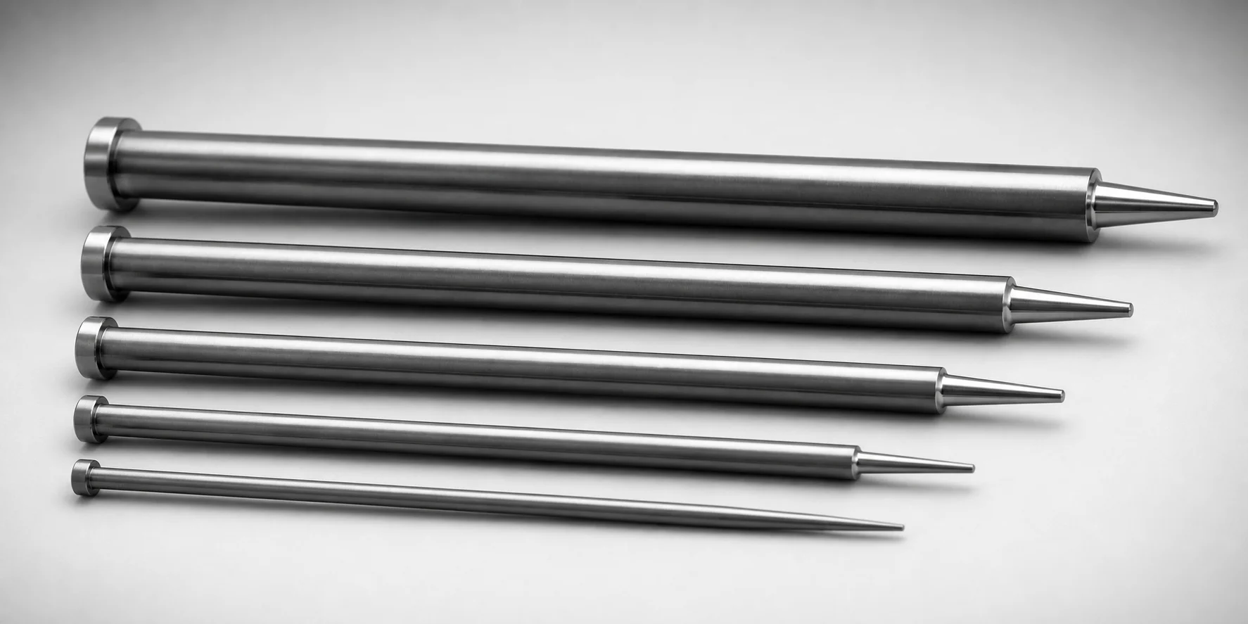
- Configurable geometry: step shape (A, B, C, D, E) and tip shape (No processing, B, C, G, R, T) change the seating profile; verify compatibility with the mating sleeve and keying approach.
Frequently Asked Questions
Which shaft diameter (D/P) sizes are available to target H7 sleeve-hole fit for center pin locating?+
The shaft diameter D/P is provided across 1.5 ~ 15 mm. For this series, the design is intended for accurate fit to H7 sleeve holes, so you should select the closest D/P size that corresponds to the H7 sleeve-hole diameter used in your die layout.
Is the shaft diameter length (F) fixed, and how does that affect die stack-up selection?+
Yes. In the supplied specifications, F (shaft diameter length) = 50 mm is fixed. When selecting an overall L dimension (70 ~ 400 / 70 ~ 500 / 70 ~ 600 / 70 ~ 700 ranges), confirm your die’s stack-up allows the fixed effective locating length to seat properly in the sleeve.
What is the purpose of the flat-sided one-step head, and how does it influence assembly repeatability?+
The flat-sided one-step head is intended to improve anti-rotation positioning during installation and repeated clamp cycles. This helps maintain consistent center alignment by reducing rotational drift at the locating interface where the pin seats into the sleeve.
What steel and surface treatment are used, and what performance benefit should we expect for wear?+
The pin uses DIN SKD61 steel in a nitrided condition. SKD61 is commonly treated as equivalent to AISI H13; nitriding enhances surface wear resistance at the contact zone while retaining core toughness, supporting stable locating through production cycles.
Which tip tolerances and tip shapes are available for precise location, and where do they matter most?+
The tip tolerance A/V is listed as ±0.02, ±0.02 (as shown with a different symbol), and ±0.01, and tip shapes include No processing, B, C, G, R, T. These options matter most for the seating/contact profile and fit at the tip region that interfaces with the mating sleeve or locating features.
Related Products
Need Custom Specifications?
Our engineering team can help with custom configurations, material selection, and volume pricing.