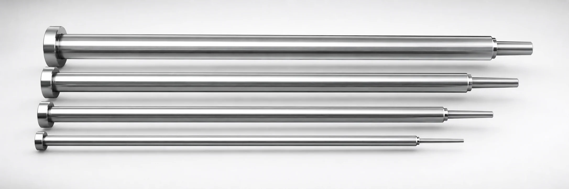
JIS Standard SKH51 Steel One-Step Center Pins
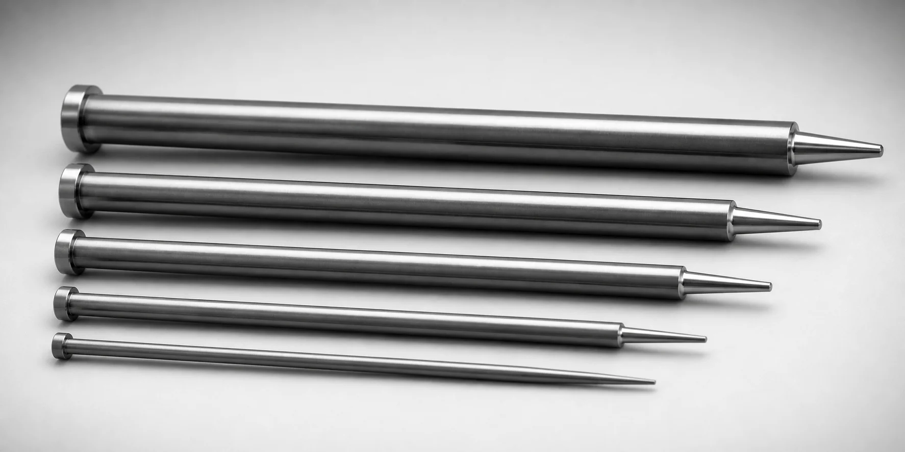
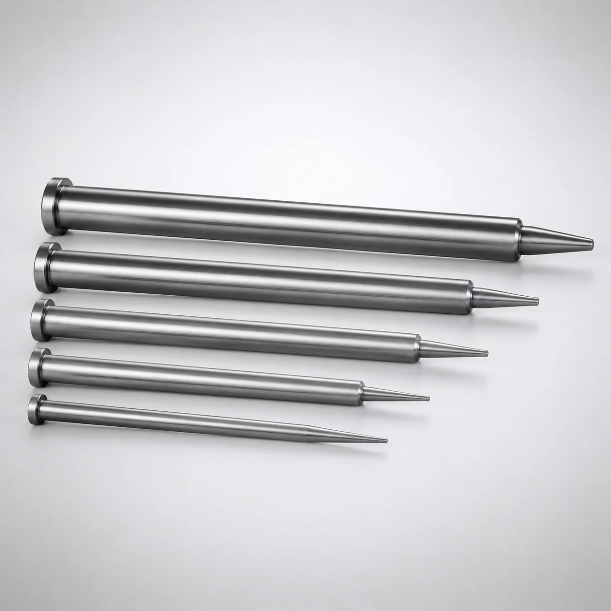
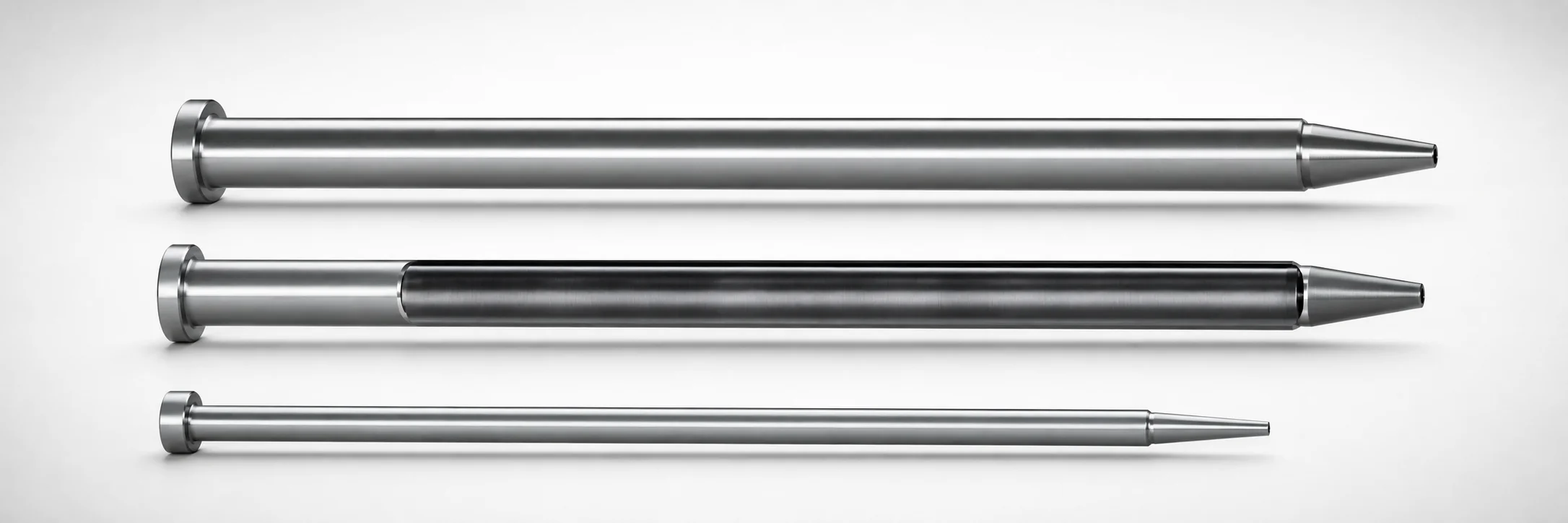
One-Step center pins (SKH51 steel) are designed for precise center positioning in jigs and dies, combining a one-step geometry with stable fit control. Built for reliable alignment through repeated production cycles.
- One-step center pin shape supports consistent locating and easy assembly
- SKH51 steel construction with hardened-steel wear resistance for long life
- Shaft diameter controlled to 0/−0.005 mm for dependable sleeve-hole fit
- JIS-standard manufacturing approach for compatibility with tooling interfaces
Specifications
1816 configurations available
| Head Thickness | D/P (Shaft Diameter) (mm) | Step Shape | Tip Shape | A/V (Tip tolerance) | No. (Nominal diameter) (mm) | A (Tip part) (mm) | C (Tip part) (mm) | F (Shaft diameter length) (mm) | G (Tip C chamfering width on the tip part) (mm) | K (Tip part angle) (°) | L (L dimension) (mm) | Q (Tip R chamfering on the tip part) (mm) | R (Tip part) (mm) | S (Tip tapered width on the tip part) (mm) | V (Tip diameter in the tip part) (mm) | type |
|---|---|---|---|---|---|---|---|---|---|---|---|---|---|---|---|---|
| 4mm(T4) | 0.8 ~ 0.99 | A | No processing | ±0.01 | 1 | - | - | 50 ~ 199.5 | - | - | 70 ~ 200 | - | - | - | 0.5 ~ 0.99 | - |
| 4mm(T4) | 1 ~ 1.49 | A | No processing | ±0.01 | 1.5 | - | - | 50 ~ 245.5 | - | - | 70 ~ 250 | - | - | - | 0.5 ~ 1.49 | - |
| 4mm(T4) | 1.5 ~ 1.99 | A | No processing | ±0.01 | 2 | - | - | 50 ~ 299.5 | - | - | 70 ~ 300 | - | - | - | 0.7 ~ 1.98 | - |
| 4mm(T4) | 2 ~ 2.49 | A | No processing | ±0.01 | 2.5 | - | - | 50 ~ 299.5 | - | - | 70 ~ 300 | - | - | - | 0.7 ~ 2.48 | - |
| 4mm(T4) | 2.5 ~ 2.99 | A | No processing | ±0.01 | 3 | - | - | 50 ~ 299.5 | - | - | 70 ~ 300 | - | - | - | 1 ~ 2.98 | - |
| 4mm(T4) | 3 ~ 3.49 | A | No processing | ±0.01 | 3.5 | - | - | 50 ~ 299.5 | - | - | 70 ~ 300 | - | - | - | 1 ~ 3.48 | - |
| 4mm(T4) | 3.5 ~ 3.99 | A | No processing | ±0.01 | 4 | - | - | 50 ~ 299.5 | - | - | 70 ~ 300 | - | - | - | 1 ~ 3.98 | - |
| 4mm(T4) | 4 ~ 4.49 | A | No processing | ±0.01 | 4.5 | - | - | 50 ~ 295.5 | - | - | 70 ~ 300 | - | - | - | 1.5 ~ 4.48 | - |
| 4mm(T4) | 4.5 ~ 4.99 | A | No processing | ±0.01 | 5 | - | - | 50 ~ 349.5 | - | - | 70 ~ 350 | - | - | - | 1.5 ~ 4.98 | - |
| 4mm(T4) | 5 ~ 5.49 | A | No processing | ±0.01 | 5.5 | - | - | 50 ~ 349.5 | - | - | 70 ~ 350 | - | - | - | 2 ~ 5.48 | - |
| 4mm(T4) | 5.5 ~ 5.99 | A | No processing | ±0.01 | 6 | - | - | 50 ~ 349.5 | - | - | 70 ~ 350 | - | - | - | 2 ~ 5.98 | - |
| 4mm(T4) | 6 ~ 6.49 | A | No processing | ±0.01 | 6.5 | - | - | 50 ~ 349.5 | - | - | 70 ~ 350 | - | - | - | 2 ~ 6.48 | - |
| 4mm(T4) | 6.5 ~ 6.99 | A | No processing | ±0.01 | 7 | - | - | 50 ~ 349.5 | - | - | 70 ~ 350 | - | - | - | 2 ~ 6.98 | - |
| 4mm(T4) | 7 ~ 7.99 | A | No processing | ±0.01 | 8 | - | - | 50 ~ 349.5 | - | - | 70 ~ 350 | - | - | - | 2 ~ 7.98 | - |
| 4mm(T4) | 8 ~ 9.99 | A | No processing | ±0.01 | 10 | - | - | 50 ~ 349.5 | - | - | 70 ~ 350 | - | - | - | 2 ~ 9.99 | - |
| 4mm(T4) | 10 ~ 11.99 | A | No processing | ±0.01 | 12 | - | - | 50 ~ 349.5 | - | - | 70 ~ 350 | - | - | - | 2 ~ 11.99 | - |
| 4mm(T4) | 1 ~ 1.49 | A | B | ±0.01 | 1.5 | - | - | 50 ~ 249.5 | - | - | 70 ~ 250 | - | - | - | 0.5 ~ 1.49 | - |
| 4mm(T4) | 1.5 ~ 1.99 | A | B | ±0.01 | 2 | - | - | 50 ~ 299.5 | - | - | 70 ~ 300 | - | - | - | 0.7 ~ 1.99 | - |
| 4mm(T4) | 2 ~ 2.49 | A | B | ±0.01 | 2.5 | - | - | 50 ~ 299.5 | - | - | 70 ~ 300 | - | - | - | 0.7 ~ 2.49 | - |
| 4mm(T4) | 2.5 ~ 2.99 | A | B | ±0.01 | 3 | - | - | 50 ~ 299.5 | - | - | 70 ~ 300 | - | - | - | 1 ~ 2.99 | - |
| 4mm(T4) | 3 ~ 3.49 | A | B | ±0.01 | 3.5 | - | - | 50 ~ 299.5 | - | - | 70 ~ 300 | - | - | - | 1 ~ 3.49 | - |
| 4mm(T4) | 3.5 ~ 3.99 | A | B | ±0.01 | 4 | - | - | 50 ~ 299.5 | - | - | 70 ~ 300 | - | - | - | 1 ~ 3.99 | - |
| 4mm(T4) | 4 ~ 4.49 | A | B | ±0.01 | 4.5 | - | - | 50 ~ 299.5 | - | - | 70 ~ 300 | - | - | - | 1.5 ~ 4.49 | - |
| 4mm(T4) | 4.5 ~ 4.99 | A | B | ±0.01 | 5 | - | - | 50 ~ 349.5 | - | - | 70 ~ 350 | - | - | - | 1.5 ~ 4.99 | - |
| 4mm(T4) | 5 ~ 5.49 | A | B | ±0.01 | 5.5 | - | - | 50 ~ 349.5 | - | - | 70 ~ 350 | - | - | - | 1.5 ~ 5.49 | - |
| 4mm(T4) | 5.5 ~ 5.99 | A | B | ±0.01 | 6 | - | - | 50 ~ 349.5 | - | - | 70 ~ 350 | - | - | - | 2 ~ 5.99 | - |
| 4mm(T4) | 6 ~ 6.49 | A | B | ±0.01 | 6.5 | - | - | 50 ~ 349.5 | - | - | 70 ~ 350 | - | - | - | 2 ~ 6.49 | - |
| 4mm(T4) | 6.5 ~ 6.99 | A | B | ±0.01 | 7 | - | - | 50 ~ 349.5 | - | - | 70 ~ 350 | - | - | - | 2 ~ 6.99 | - |
| 4mm(T4) | 7 ~ 7.99 | A | B | ±0.01 | 8 | - | - | 50 ~ 349.5 | - | - | 70 ~ 350 | - | - | - | 2 ~ 7.99 | - |
| 4mm(T4) | 8 ~ 9.99 | A | B | ±0.01 | 10 | - | - | 50 ~ 349.5 | - | - | 70 ~ 350 | - | - | - | 2 ~ 9.99 | - |
| 4mm(T4) | 10 ~ 11.99 | A | B | ±0.01 | 12 | - | - | 50 ~ 349.5 | - | - | 70 ~ 350 | - | - | - | 2 ~ 11.99 | - |
| 4mm(T4) | 1 ~ 1.49 | A | C | ±0.01 | 1.5 | - | - | 50 ~ 249.5 | 0.5 ~ 0.7 | - | 70 ~ 250 | - | - | - | 0.5 ~ 1.49 | - |
| 4mm(T4) | 1.5 ~ 1.99 | A | C | ±0.01 | 2 | - | - | 50 ~ 299.5 | 0.5 ~ 0.9 | - | 70 ~ 300 | - | - | - | 0.7 ~ 1.99 | - |
| 4mm(T4) | 2 ~ 2.49 | A | C | ±0.01 | 2.5 | - | - | 50 ~ 299.5 | 0.5 ~ 1.2 | - | 70 ~ 300 | - | - | - | 0.7 ~ 2.49 | - |
| 4mm(T4) | 2.5 ~ 2.99 | A | C | ±0.01 | 3 | - | - | 50 ~ 299.5 | 0.5 ~ 1.4 | - | 70 ~ 300 | - | - | - | 1 ~ 2.99 | - |
| 4mm(T4) | 3 ~ 3.49 | A | C | ±0.01 | 3.5 | - | - | 50 ~ 299.5 | 0.5 ~ 1.7 | - | 70 ~ 300 | - | - | - | 1 ~ 3.49 | - |
| 4mm(T4) | 3.5 ~ 3.99 | A | C | ±0.01 | 4 | - | - | 50 ~ 299.5 | 0.5 ~ 1.9 | - | 70 ~ 300 | - | - | - | 1 ~ 3.99 | - |
| 4mm(T4) | 4 ~ 4.49 | A | C | ±0.01 | 4.5 | - | - | 50 ~ 299.5 | 0.5 ~ 2.2 | - | 70 ~ 300 | - | - | - | 1.5 ~ 4.49 | - |
| 4mm(T4) | 4.5 ~ 4.99 | A | C | ±0.01 | 5 | - | - | 50 ~ 349.5 | 0.5 ~ 2.4 | - | 70 ~ 350 | - | - | - | 1.5 ~ 4.99 | - |
| 4mm(T4) | 5 ~ 5.49 | A | C | ±0.01 | 5.5 | - | - | 50 ~ 349.5 | 0.5 ~ 2.7 | - | 70 ~ 350 | - | - | - | 1.5 ~ 5.49 | - |
| 4mm(T4) | 5.5 ~ 5.99 | A | C | ±0.01 | 6 | - | - | 50 ~ 349.5 | 0.5 ~ 2.9 | - | 70 ~ 350 | - | - | - | 2 ~ 5.99 | - |
| 4mm(T4) | 6 ~ 6.49 | A | C | ±0.01 | 6.5 | - | - | 50 ~ 349.5 | 0.5 ~ 3.2 | - | 70 ~ 350 | - | - | - | 2 ~ 6.49 | - |
| 4mm(T4) | 6.5 ~ 6.99 | A | C | ±0.01 | 7 | - | - | 50 ~ 349.5 | 0.5 ~ 3.4 | - | 70 ~ 350 | - | - | - | 2 ~ 6.99 | - |
| 4mm(T4) | 7 ~ 7.99 | A | C | ±0.01 | 8 | - | - | 50 ~ 349.5 | 0.5 ~ 3.9 | - | 70 ~ 350 | - | - | - | 2 ~ 7.99 | - |
| 4mm(T4) | 8 ~ 9.99 | A | C | ±0.01 | 10 | - | - | 50 ~ 349.5 | 0.5 ~ 4.9 | - | 70 ~ 350 | - | - | - | 2 ~ 9.99 | - |
| 4mm(T4) | 10 ~ 11.99 | A | C | ±0.01 | 12 | - | - | 50 ~ 349.5 | 0.5 ~ 6.4 | - | 70 ~ 350 | - | - | - | 2 ~ 11.99 | - |
| 4mm(T4) | 1 ~ 1.49 | A | G | ±0.01 | 1.5 | - | - | 50 ~ 249.5 | - | 21 ~ 60 | 70 ~ 250 | - | - | - | 0.5 ~ 1.49 | - |
| 4mm(T4) | 1.5 ~ 1.99 | A | G | ±0.01 | 2 | - | - | 50 ~ 299.5 | - | 21 ~ 60 | 70 ~ 300 | - | - | - | 0.7 ~ 1.99 | - |
| 4mm(T4) | 2 ~ 2.49 | A | G | ±0.01 | 2.5 | - | - | 50 ~ 299.5 | - | 21 ~ 60 | 70 ~ 300 | - | - | - | 0.7 ~ 2.49 | - |
| 4mm(T4) | 2.5 ~ 2.99 | A | G | ±0.01 | 3 | - | - | 50 ~ 299.5 | - | 21 ~ 60 | 70 ~ 300 | - | - | - | 1 ~ 2.99 | - |
Product Guide
Application Scenarios+
One-step center pins are used in injection mold tooling to establish repeatable center positioning between a mating jig, die set, or locating sleeve. Their one-step geometry helps the assembler achieve stable axial location during build-up, reducing the risk of drift over repeated cycles.
- Automotive connector and housing molds: Use the controlled shaft diameter (D/P 0.8–10 mm with 0/−0.005 mm control) to maintain consistent alignment of locating sleeves and improve part-to-part positional repeatability on high-run production.
- Medical device housings and fixture tooling: The JIS-standard manufacture and consistent tip/taper geometry support reliable centering during jig loading, helping maintain concentricity for precision components.
- General jigs and dies: Select the appropriate step shape (A–E) and tip processing option to match the receiving block/fixture features, allowing easy assembly with predictable fit.
Material & Process Details+
This variant uses JIS Standard SKH51 steel, a hardened high-speed steel grade commonly selected for locating components that must resist wear. In service, the hardened condition supports high wear resistance at the pin/sleeve contact areas, improving dimensional stability across repeated assembly cycles.
- Wear vs. toughness balance: SKH51’s hardness provides durable sliding and contact wear performance, while some toughness trade-off can occur compared with tougher mold steels—this makes correct fit and alignment important to avoid edge loading.
- Heat treatment state: The product is manufactured as a hardened-steel center pin design intended for long-life wear resistance in jigs and dies.
- Typical comparison: If you need higher shock toughness, alternative die steels may be considered; however, for sleeve-hole centering durability, SKH51’s wear-focused hardened performance is the intent.
Sizing & Selection Guide+
To select the correct one-step center pin, match both shaft diameter and the one-step geometry to the mating sleeve-hole and receiving fixture features. Start with D/P (shaft diameter) = 0.8–10 mm and confirm the shaft fit control to 0/−0.005 mm, which is critical for reliable sleeve-hole engagement.
- Choose nominal diameter: Use No. (nominal diameter) 1–12 as your catalog baseline, then verify the corresponding shaft diameter D/P.
- Select step and tip geometry: Pick the required step shape (A, B, C, D, E) and tip shape (No processing, B, C, G, R, T) based on the receiving part’s counter/center features.
- Check overall dimensions: Use Head thickness options (T4, 4 mm JIS, 6 mm JIS, 8 mm JIS) and L range (70–200/250/300/350 up to 70–300 depending on option) to ensure clearance and correct engagement length.
- Tolerance guidance: Tip tolerance is specified as ±0.01 or ±0.005, so choose the tighter tolerance when you require higher centering repeatability.
Frequently Asked Questions
What shaft diameter tolerance should I expect for SKH51 one-step center pins, and how does it affect sleeve-hole fit?+
The shaft diameter (D/P) is specified from 0.8 to 10 mm with a tight control of 0/−0.005 mm. This negative-side control helps maintain predictable engagement with the mating sleeve-hole and supports consistent centering over repeated builds.
How do I choose between the available head thickness options (T4, 4 mm JIS, 6 mm JIS, 8 mm JIS) for my jig/die?+
Select head thickness based on the available stack-up space and the required support/retention behavior in your tooling. The product offers 4 mm (T4), 4 mm (JIS), 6 mm (JIS), and 8 mm (JIS) variants, so confirm clearance and contact conditions at assembly.
Which tip shapes and tolerance levels are available, and what should I consider for centering accuracy?+
Tip shapes include options such as No processing and processed types B, C, G, R, T. Tip tolerance (A/V) is specified as ±0.01 or ±0.005, so use the tighter value when your receiving features require higher concentricity or reduced locating variance.
What are the step shape choices (A–E), and how do they impact assembly with the receiving block?+
The one-step geometry is available in step shapes A, B, C, D, E. The correct step shape should match the corresponding counter/shoulder features of the receiving block so the pin seats consistently and prevents axial mislocation during repeated cycles.
How do I verify overall length (L) when selecting a one-step center pin for different die sizes?+
Overall length is specified across multiple ranges depending on the option, including L = 70–200, 70–250, 70–300, and 70–350, with catalog note showing up to 70–300 for at least one variant. Confirm that your selected L provides sufficient engagement length without interference with moving components or adjacent hardware.
Related Products
Need Custom Specifications?
Our engineering team can help with custom configurations, material selection, and volume pricing.