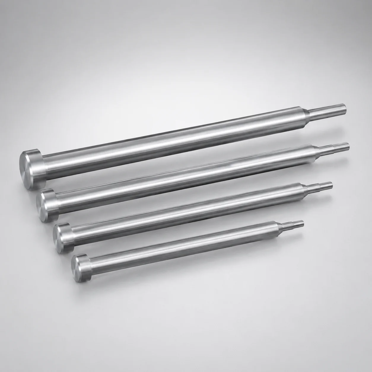
SKH51 Steel One-Step Center Pins
SKH51 steel one-step center pins provide precise alignment with a compact one-step geometry designed for repeatable placement in locating systems. The hardened construction improves wear resistance for demanding press and die applications.
- One-step design supports stable locating during die setup and operation
- High-performance SKH51 steel with heat-treated hardened construction
- Compatible with sleeve hole fits using +0.01/0 or H7 guidance
- Suitable for mold and die alignment, especially where consistent positional accuracy matters
Specifications
2724 configurations available
| Head Thickness | D/P (Shaft Diameter) (mm) | Step Shape | Tip Shape | A/V (Tip tolerance) | No. (Nominal diameter) (mm) | A (Tip part) (mm) | C (Tip part) (mm) | F (Shaft diameter length) (mm) | G (Tip C chamfering width on the tip part) (mm) | K (Tip part angle) (°) | L (L dimension) (mm) | Q (Tip R chamfering on the tip part) (mm) | R (Tip part) (mm) | S (Tip tapered width on the tip part) (mm) | V (Tip diameter in the tip part) (mm) | type |
|---|---|---|---|---|---|---|---|---|---|---|---|---|---|---|---|---|
| 4mm(T4) | 0.8 ~ 0.99 | A | No processing | ±0.01 | 1 | - | - | 50 ~ 149.5 | - | - | 70 ~ 200 | - | - | - | 0.5 ~ 0.99 | - |
| 4mm(T4) | 1 ~ 1.49 | A | No processing | ±0.01 | 1.5 | - | - | 50 ~ 195.5 | - | - | 70 ~ 250 | - | - | - | 0.5 ~ 1.49 | - |
| 4mm(T4) | 1.5 ~ 1.99 | A | No processing | ±0.01 | 2 | - | - | 50 ~ 249.5 | - | - | 70 ~ 250 | - | - | - | 0.7 ~ 1.98 | - |
| 4mm(T4) | 2 ~ 2.49 | A | No processing | ±0.01 | 2.5 | - | - | 50 ~ 249.5 | - | - | 70 ~ 250 | - | - | - | 0.7 ~ 2.48 | - |
| 4mm(T4) | 2.5 ~ 2.99 | A | No processing | ±0.01 | 3 | - | - | 50 ~ 299.5 | - | - | 70 ~ 300 | - | - | - | 1 ~ 2.98 | - |
| 4mm(T4) | 3 ~ 3.49 | A | No processing | ±0.01 | 3.5 | - | - | 50 ~ 299.5 | - | - | 70 ~ 300 | - | - | - | 1 ~ 3.48 | - |
| 4mm(T4) | 3.5 ~ 3.99 | A | No processing | ±0.01 | 4 | - | - | 50 ~ 299.5 | - | - | 70 ~ 300 | - | - | - | 1 ~ 3.98 | - |
| 4mm(T4) | 4 ~ 4.49 | A | No processing | ±0.01 | 4.5 | - | - | 50 ~ 295.5 | - | - | 70 ~ 300 | - | - | - | 1.5 ~ 4.48 | - |
| 4mm(T4) | 4.5 ~ 4.99 | A | No processing | ±0.01 | 5 | - | - | 50 ~ 349.5 | - | - | 70 ~ 350 | - | - | - | 1.5 ~ 4.98 | - |
| 4mm(T4) | 5 ~ 5.49 | A | No processing | ±0.01 | 5.5 | - | - | 50 ~ 349.5 | - | - | 70 ~ 350 | - | - | - | 2 ~ 5.48 | - |
| 4mm(T4) | 5.5 ~ 5.99 | A | No processing | ±0.01 | 6 | - | - | 50 ~ 349.5 | - | - | 70 ~ 350 | - | - | - | 2 ~ 5.98 | - |
| 4mm(T4) | 6 ~ 6.49 | A | No processing | ±0.01 | 6.5 | - | - | 50 ~ 349.5 | - | - | 70 ~ 350 | - | - | - | 2 ~ 6.48 | - |
| 4mm(T4) | 6.5 ~ 6.99 | A | No processing | ±0.01 | 7 | - | - | 50 ~ 349.5 | - | - | 70 ~ 350 | - | - | - | 2 ~ 6.98 | - |
| 4mm(T4) | 7 ~ 7.99 | A | No processing | ±0.01 | 8 | - | - | 50 ~ 349.5 | - | - | 70 ~ 350 | - | - | - | 2 ~ 7.98 | - |
| 4mm(T4) | 8 ~ 9.99 | A | No processing | ±0.01 | 10 | - | - | 50 ~ 349.5 | - | - | 70 ~ 350 | - | - | - | 2 ~ 9.99 | - |
| 4mm(T4) | 10 ~ 11.99 | A | No processing | ±0.01 | 12 | - | - | 50 ~ 349.5 | - | - | 70 ~ 350 | - | - | - | 2 ~ 11.99 | - |
| 4mm(T4) | 1 ~ 1.49 | A | B | ±0.01 | 1.5 | - | - | 50 ~ 249.5 | - | - | 70 ~ 250 | - | - | - | 0.5 ~ 1.49 | - |
| 4mm(T4) | 1.5 ~ 1.99 | A | B | ±0.01 | 2 | - | - | 50 ~ 249.5 | - | - | 70 ~ 250 | - | - | - | 0.7 ~ 1.99 | - |
| 4mm(T4) | 2 ~ 2.49 | A | B | ±0.01 | 2.5 | - | - | 50 ~ 249.5 | - | - | 70 ~ 250 | - | - | - | 0.7 ~ 2.49 | - |
| 4mm(T4) | 2.5 ~ 2.99 | A | B | ±0.01 | 3 | - | - | 50 ~ 299.5 | - | - | 70 ~ 300 | - | - | - | 1 ~ 2.99 | - |
| 4mm(T4) | 3 ~ 3.49 | A | B | ±0.01 | 3.5 | - | - | 50 ~ 299.5 | - | - | 70 ~ 300 | - | - | - | 1 ~ 3.49 | - |
| 4mm(T4) | 3.5 ~ 3.99 | A | B | ±0.01 | 4 | - | - | 50 ~ 299.5 | - | - | 70 ~ 300 | - | - | - | 1 ~ 3.99 | - |
| 4mm(T4) | 4 ~ 4.49 | A | B | ±0.01 | 4.5 | - | - | 50 ~ 299.5 | - | - | 70 ~ 300 | - | - | - | 1.5 ~ 4.49 | - |
| 4mm(T4) | 4.5 ~ 4.99 | A | B | ±0.01 | 5 | - | - | 50 ~ 349.5 | - | - | 70 ~ 350 | - | - | - | 1.5 ~ 4.99 | - |
| 4mm(T4) | 5 ~ 5.49 | A | B | ±0.01 | 5.5 | - | - | 50 ~ 349.5 | - | - | 70 ~ 350 | - | - | - | 1.5 ~ 5.49 | - |
| 4mm(T4) | 5.5 ~ 5.99 | A | B | ±0.01 | 6 | - | - | 50 ~ 349.5 | - | - | 70 ~ 350 | - | - | - | 2 ~ 5.99 | - |
| 4mm(T4) | 6 ~ 6.49 | A | B | ±0.01 | 6.5 | - | - | 50 ~ 349.5 | - | - | 70 ~ 350 | - | - | - | 2 ~ 6.49 | - |
| 4mm(T4) | 6.5 ~ 6.99 | A | B | ±0.01 | 7 | - | - | 50 ~ 349.5 | - | - | 70 ~ 350 | - | - | - | 2 ~ 6.99 | - |
| 4mm(T4) | 7 ~ 7.99 | A | B | ±0.01 | 8 | - | - | 50 ~ 349.5 | - | - | 70 ~ 350 | - | - | - | 2 ~ 7.99 | - |
| 4mm(T4) | 8 ~ 9.99 | A | B | ±0.01 | 10 | - | - | 50 ~ 349.5 | - | - | 70 ~ 350 | - | - | - | 2 ~ 9.99 | - |
| 4mm(T4) | 10 ~ 11.99 | A | B | ±0.01 | 12 | - | - | 50 ~ 349.5 | - | - | 70 ~ 350 | - | - | - | 2 ~ 11.99 | - |
| 4mm(T4) | 1 ~ 1.49 | A | C | ±0.01 | 1.5 | - | - | 50 ~ 249.5 | 0.5 ~ 0.7 | - | 70 ~ 250 | - | - | - | 0.5 ~ 1.49 | - |
| 4mm(T4) | 1.5 ~ 1.99 | A | C | ±0.01 | 2 | - | - | 50 ~ 249.5 | 0.5 ~ 0.9 | - | 70 ~ 250 | - | - | - | 0.7 ~ 1.99 | - |
| 4mm(T4) | 2 ~ 2.49 | A | C | ±0.01 | 2.5 | - | - | 50 ~ 249.5 | 0.5 ~ 1.2 | - | 70 ~ 250 | - | - | - | 0.7 ~ 2.49 | - |
| 4mm(T4) | 2.5 ~ 2.99 | A | C | ±0.01 | 3 | - | - | 50 ~ 299.5 | 0.5 ~ 1.4 | - | 70 ~ 300 | - | - | - | 1 ~ 2.99 | - |
| 4mm(T4) | 3 ~ 3.49 | A | C | ±0.01 | 3.5 | - | - | 50 ~ 299.5 | 0.5 ~ 1.7 | - | 70 ~ 300 | - | - | - | 1 ~ 3.49 | - |
| 4mm(T4) | 3.5 ~ 3.99 | A | C | ±0.01 | 4 | - | - | 50 ~ 299.5 | 0.5 ~ 1.9 | - | 70 ~ 300 | - | - | - | 1 ~ 3.99 | - |
| 4mm(T4) | 4 ~ 4.49 | A | C | ±0.01 | 4.5 | - | - | 50 ~ 299.5 | 0.5 ~ 2.2 | - | 70 ~ 300 | - | - | - | 1.5 ~ 4.49 | - |
| 4mm(T4) | 4.5 ~ 4.99 | A | C | ±0.01 | 5 | - | - | 50 ~ 349.5 | 0.5 ~ 2.4 | - | 70 ~ 350 | - | - | - | 1.5 ~ 4.99 | - |
| 4mm(T4) | 5 ~ 5.49 | A | C | ±0.01 | 5.5 | - | - | 50 ~ 349.5 | 0.5 ~ 2.7 | - | 70 ~ 350 | - | - | - | 1.5 ~ 5.49 | - |
| 4mm(T4) | 5.5 ~ 5.99 | A | C | ±0.01 | 6 | - | - | 50 ~ 349.5 | 0.5 ~ 2.9 | - | 70 ~ 350 | - | - | - | 2 ~ 5.99 | - |
| 4mm(T4) | 6 ~ 6.49 | A | C | ±0.01 | 6.5 | - | - | 50 ~ 349.5 | 0.5 ~ 3.2 | - | 70 ~ 350 | - | - | - | 2 ~ 6.49 | - |
| 4mm(T4) | 6.5 ~ 6.99 | A | C | ±0.01 | 7 | - | - | 50 ~ 349.5 | 0.5 ~ 3.4 | - | 70 ~ 350 | - | - | - | 2 ~ 6.99 | - |
| 4mm(T4) | 7 ~ 7.99 | A | C | ±0.01 | 8 | - | - | 50 ~ 349.5 | 0.5 ~ 3.9 | - | 70 ~ 350 | - | - | - | 2 ~ 7.99 | - |
| 4mm(T4) | 8 ~ 9.99 | A | C | ±0.01 | 10 | - | - | 50 ~ 349.5 | 0.5 ~ 4.9 | - | 70 ~ 350 | - | - | - | 2 ~ 9.99 | - |
| 4mm(T4) | 10 ~ 11.99 | A | C | ±0.01 | 12 | - | - | 50 ~ 349.5 | 0.5 ~ 6.4 | - | 70 ~ 350 | - | - | - | 2 ~ 11.99 | - |
| 4mm(T4) | 1 ~ 1.49 | A | G | ±0.01 | 1.5 | - | - | 50 ~ 249.5 | - | 21 ~ 60 | 70 ~ 250 | - | - | - | 0.5 ~ 1.49 | - |
| 4mm(T4) | 1.5 ~ 1.99 | A | G | ±0.01 | 2 | - | - | 50 ~ 249.5 | - | 21 ~ 60 | 70 ~ 250 | - | - | - | 0.7 ~ 1.99 | - |
| 4mm(T4) | 2 ~ 2.49 | A | G | ±0.01 | 2.5 | - | - | 50 ~ 249.5 | - | 21 ~ 60 | 70 ~ 250 | - | - | - | 0.7 ~ 2.49 | - |
| 4mm(T4) | 2.5 ~ 2.99 | A | G | ±0.01 | 3 | - | - | 50 ~ 299.5 | - | 21 ~ 60 | 70 ~ 300 | - | - | - | 1 ~ 2.99 | - |
Product Guide
Application Scenarios+
One-step center pins are used in injection mold tooling as a locating element between the mold base, die, and guide/sleeve system. The compact step geometry helps maintain repeatable positioning during die setup, reducing variability when the mold is removed and reinstalled.
- Automotive connector and small housing molds: ideal where thin alignment features and frequent service cycles demand stable sleeve location; the hardened SKH51 construction supports long-running alignment under contact wear.
- Electronics enclosures and precision brackets: the one-step interface promotes consistent die setting, helping maintain parting-line and cavity register stability during high cycle production.
- Press tooling and transfer fixtures: suitable for setups that require reliable orientation repeatability; tip/tolerance options (e.g., ±0.01, ±0.005, ±0.02) support fine fit with sleeve hole references.
Choose this variant when sleeve fit control and durable, hardened contact surfaces are critical to alignment accuracy.
Material & Process Details+
SKH51 steel is a high-performance die/punching tool steel used for wear-resistant alignment components. In this hardened center pin application, it is selected to provide a good balance of wear resistance at the locating tip and sufficient toughness for repeated assembly/disassembly.
- Heat treatment: provided in a hardened construction state appropriate for high-contact locating use (pin-to-sleeve interface).
- Hardness and trade-offs: hardened SKH51 typically reaches high HRC levels to resist polishing/peening; higher hardness improves wear performance but can reduce toughness if over-tempered or if mounting stress is excessive.
- Manufacturing process: typically involves machining of the stepped geometry, tip contouring, then hardening and finishing to maintain tip tolerance for controlled locating.
- Material comparison: compared to lower-alloy, non-hardened steels, SKH51 offers superior wear durability for sleeve locating, but requires proper heat treatment control to avoid brittleness.
Sizing & Selection Guide+
Selection starts with matching the shaft diameter (D/P) and the nominal diameter (No.) to your locating sleeve bore and guide system. This product supports D/P = 0.8 ~ 10 mm, with No. = 1 ~ 12, so choose the closest sleeve reference size to ensure proper engagement.
- Length/engagement: use the shaft length feature F = 50 ~ 70 mm for overall reach, and select the overall L according to mold thickness/spacing requirements (available ranges: 70 ~ 200, 70 ~ 250, 70 ~ 300, 70 ~ 350, and 70+).
- Fit and tolerance: the locating interface is intended for sleeve hole fits using +0.01/0 or H7 guidance; align the pin tip/tolerance to your sleeve clearance strategy (tip tolerance options include ±0.01, ±0.005, ±0.02).
- Tip geometry: choose the step shape (A, B, C, D, E) and tip shape (e.g., no processing, B, C, G, R, T) to match your sleeve lead-in and desired centering behavior.
Confirm that the stepped head thickness (T4 / 4mm(JIS) / 6mm(JIS) / 8mm(JIS)) fits your die setting stackup without interference.
Frequently Asked Questions
Which shaft diameter (D/P) range should I select for my sleeve hole system?+
For this SKH51 one-step center pin family, the shaft diameter D/P is available in 0.8 ~ 10 mm. Match your sleeve hole nominal size using your standard reference (the guidance provided is +0.01/0 or H7) to achieve the intended locating clearance.
How do the available tip tolerances (A/V) affect alignment repeatability?+
This product offers tip tolerance options of ±0.01, ±0.005, and ±0.02. Tighter tolerance (e.g., ±0.005) generally improves locating consistency when the sleeve hole and die setup are engineered for fine fit, while slightly looser tolerance can improve assembly robustness.
What head thickness and overall length (L) should I verify against my mold stackup?+
The head thickness is available as T4 (4mm) plus 4mm(JIS), 6mm(JIS), and 8mm(JIS). Verify head clearance in your die setting stackup, then select the overall L from the provided ranges (e.g., 70 ~ 200 up to 70 ~ 350).
Which step shape and tip shape combinations are typically used to improve sleeve lead-in?+
Use the provided step shape options (A, B, C, D, E) and select a tip shape such as B, C, G, R, or T (or no processing) to align with your sleeve lead-in geometry. Pairing the tip contour with your sleeve entry profile helps prevent mis-centering during mold installation.
Why choose SKH51 hardened pins instead of a lower-wear steel for locating pins?+
SKH51 is selected for hardened, wear-resistant performance at the locating contact zone. In repeatedly cycled mold tools, this helps resist polishing and surface degradation compared to non-optimized steels, improving long-term positional stability.
Related Products
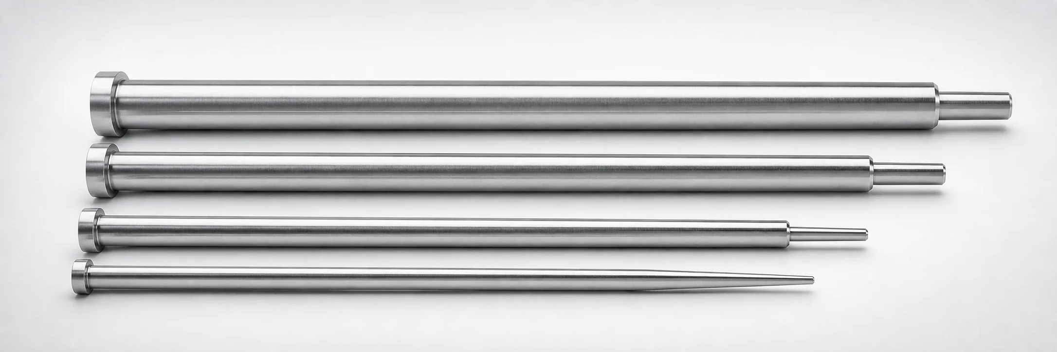
JIS Standard M2 Steel One-Step Center Pins Flat-Sided
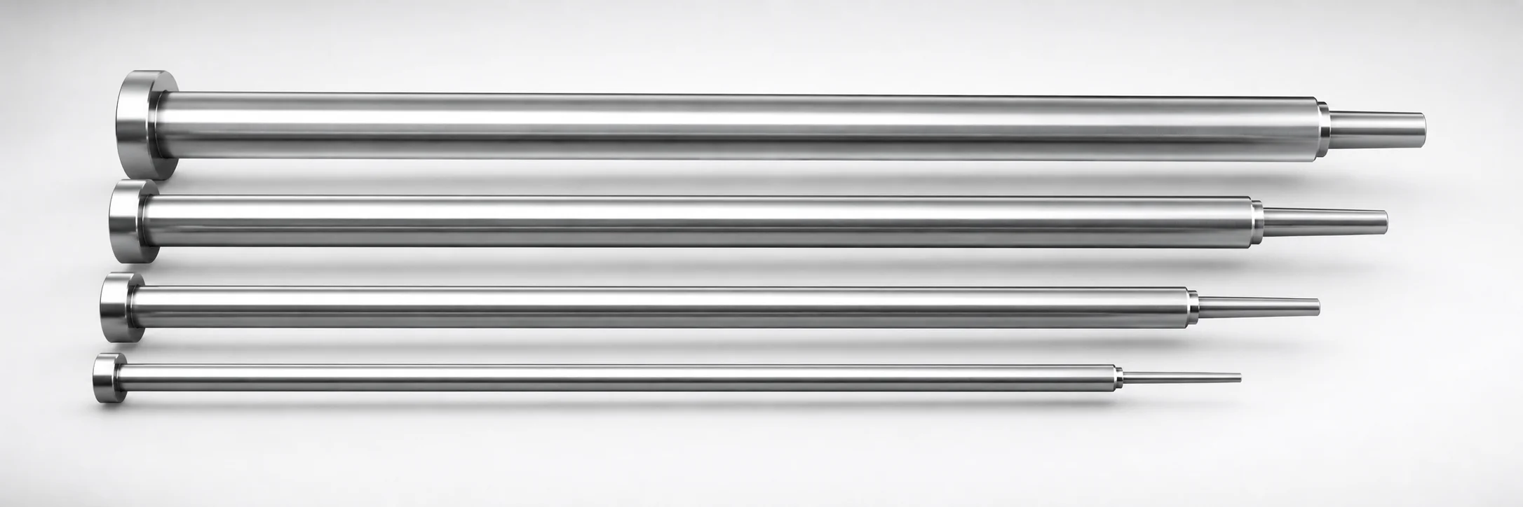
JIS Standard SKH51 Steel One-Step Center Pins
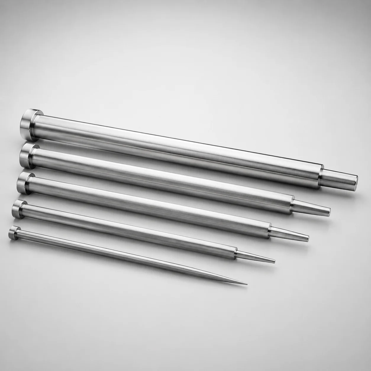
JIS Standard M2 Steel One-Step Center Pins
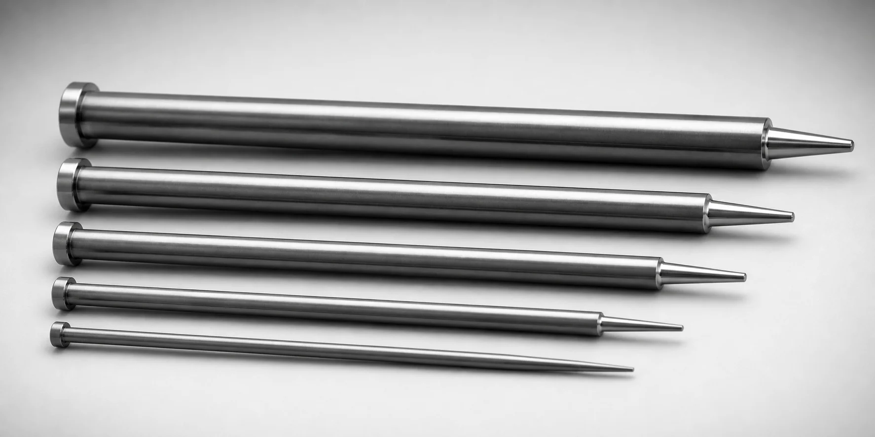
DIN Standard SKD61 Steel One-Step Center Pins (Nitrided)
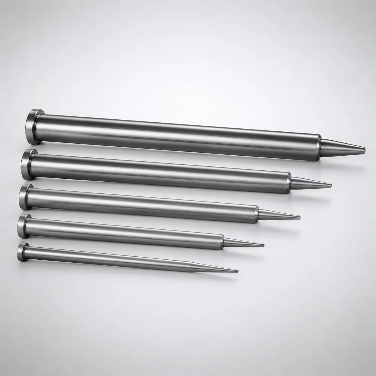
DIN Standard SKD61 Steel One-Step Center Pins Flat-Sided, Nitrided
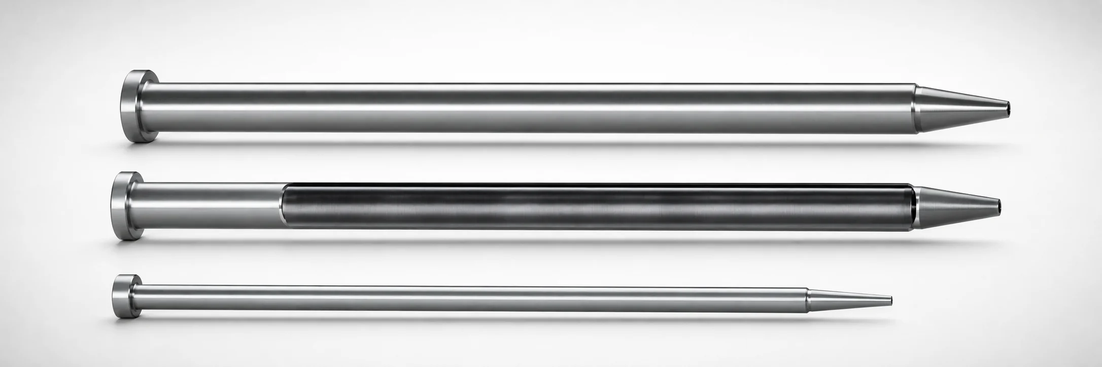
SKD61 Steel One-Step Center Pins with Cooling Hole
Need Custom Specifications?
Our engineering team can help with custom configurations, material selection, and volume pricing.