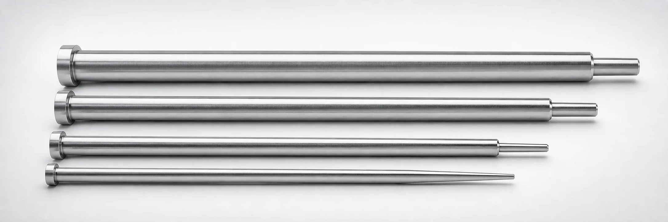
JIS Standard M2 Steel One-Step Center Pins Flat-Sided
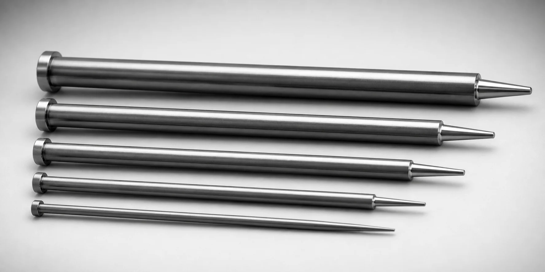
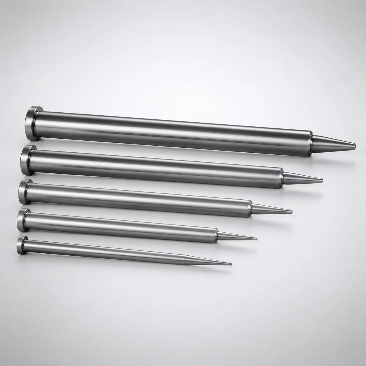
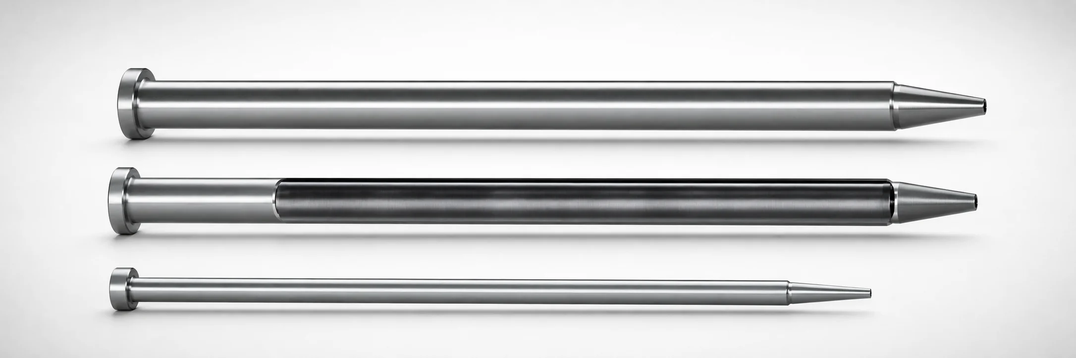
One-step center pins (SKH51 steel) are engineered for precise locating in molding applications, featuring a flat-sided head that resists rotation and helps maintain repeatable positioning. The one-step geometry supports efficient alignment during assembly.
- Flat-sided head improves anti-rotation stability for consistent center positioning
- SKH51 steel construction with hardened, wear-resistant performance for long service life
- Shaft tolerance 0/−0.005 supports reliable fit with mating sleeves
- Compatible sleeve hole tolerance +0.005/0 aids smooth insertion and repeatability
Specifications
2016 configurations available
| Head Thickness | D/P (Shaft Diameter) (mm) | Step Shape | Tip Shape | A/V (Tip tolerance) | A (Tip part) (mm) | C (Tip part) (mm) | F (Shaft diameter length) (mm) | G (Tip C chamfering width on the tip part) (mm) | K (Tip part angle) (°) | L (L dimension) (mm) | Q (Tip R chamfering on the tip part) (mm) | R (Tip part) (mm) | S (Tip tapered width on the tip part) (mm) | V (Tip diameter in the tip part) (mm) | type |
|---|---|---|---|---|---|---|---|---|---|---|---|---|---|---|---|
| 4mm(T4) | 1 | A | No processing | ±0.01 | - | - | 50 ~ 199.5 | - | - | 70 ~ 200 | - | - | - | 0.5 ~ 0.99 | - |
| 4mm(T4) | 1.5 | A | No processing | ±0.01 | - | - | 50 ~ 249.5 | - | - | 70 ~ 250 | - | - | - | 0.5 ~ 1.49 | - |
| 4mm(T4) | 2 | A | No processing | ±0.01 | - | - | 50 ~ 249.5 | - | - | 70 ~ 250 | - | - | - | 0.7 ~ 1.99 | - |
| 4mm(T4) | 2.5 | A | No processing | ±0.01 | - | - | 50 ~ 249.5 | - | - | 70 ~ 250 | - | - | - | 0.7 ~ 2.49 | - |
| 4mm(T4) | 3 | A | No processing | ±0.01 | - | - | 50 ~ 299.5 | - | - | 70 ~ 300 | - | - | - | 1 ~ 2.99 | - |
| 4mm(T4) | 3.5 | A | No processing | ±0.01 | - | - | 50 ~ 299.5 | - | - | 70 ~ 300 | - | - | - | 1 ~ 3.49 | - |
| 4mm(T4) | 4 | A | No processing | ±0.01 | - | - | 50 ~ 299.5 | - | - | 70 ~ 300 | - | - | - | 1 ~ 3.99 | - |
| 4mm(T4) | 4.5 | A | No processing | ±0.01 | - | - | 50 ~ 295.5 | - | - | 70 ~ 300 | - | - | - | 1.5 ~ 4.49 | - |
| 4mm(T4) | 5 | A | No processing | ±0.01 | - | - | 50 ~ 349.5 | - | - | 70 ~ 350 | - | - | - | 1.5 ~ 4.99 | - |
| 4mm(T4) | 5.5 | A | No processing | ±0.01 | - | - | 50 ~ 349.5 | - | - | 70 ~ 350 | - | - | - | 2 ~ 5.49 | - |
| 4mm(T4) | 6 | A | No processing | ±0.01 | - | - | 50 ~ 349.5 | - | - | 70 ~ 350 | - | - | - | 2 ~ 5.99 | - |
| 4mm(T4) | 6.5 | A | No processing | ±0.01 | - | - | 50 ~ 349.5 | - | - | 70 ~ 350 | - | - | - | 2 ~ 6.49 | - |
| 4mm(T4) | 7 | A | No processing | ±0.01 | - | - | 50 ~ 349.5 | - | - | 70 ~ 350 | - | - | - | 2 ~ 6.99 | - |
| 4mm(T4) | 8 | A | No processing | ±0.01 | - | - | 50 ~ 349.5 | - | - | 70 ~ 350 | - | - | - | 2 ~ 7.99 | - |
| 4mm(T4) | 9 | A | No processing | ±0.01 | - | - | 50 ~ 349.5 | - | - | 70 ~ 350 | - | - | - | 2 ~ 8.99 | - |
| 4mm(T4) | 10 | A | No processing | ±0.01 | - | - | 50 ~ 349.5 | - | - | 70 ~ 350 | - | - | - | 2 ~ 9.99 | - |
| 4mm(T4) | 12 | A | No processing | ±0.01 | - | - | 50 ~ 349.5 | - | - | 70 ~ 350 | - | - | - | 2 ~ 11.99 | - |
| 4mm(T4) | 1 | A | B | ±0.01 | - | - | 50 ~ 199.5 | - | - | 70 ~ 200 | - | - | - | 0.5 ~ 0.99 | - |
| 4mm(T4) | 1.5 | A | B | ±0.01 | - | - | 50 ~ 249.5 | - | - | 70 ~ 250 | - | - | - | 0.5 ~ 1.49 | - |
| 4mm(T4) | 2 | A | B | ±0.01 | - | - | 50 ~ 249.5 | - | - | 70 ~ 250 | - | - | - | 0.7 ~ 1.99 | - |
| 4mm(T4) | 2.5 | A | B | ±0.01 | - | - | 50 ~ 249.5 | - | - | 70 ~ 250 | - | - | - | 0.7 ~ 2.49 | - |
| 4mm(T4) | 3 | A | B | ±0.01 | - | - | 50 ~ 299.5 | - | - | 70 ~ 300 | - | - | - | 1 ~ 2.99 | - |
| 4mm(T4) | 3.5 | A | B | ±0.01 | - | - | 50 ~ 299.5 | - | - | 70 ~ 300 | - | - | - | 1 ~ 3.49 | - |
| 4mm(T4) | 4 | A | B | ±0.01 | - | - | 50 ~ 299.5 | - | - | 70 ~ 300 | - | - | - | 1 ~ 3.99 | - |
| 4mm(T4) | 4.5 | A | B | ±0.01 | - | - | 50 ~ 299.5 | - | - | 70 ~ 300 | - | - | - | 1.5 ~ 4.49 | - |
| 4mm(T4) | 5 | A | B | ±0.01 | - | - | 50 ~ 349.5 | - | - | 70 ~ 350 | - | - | - | 1.5 ~ 4.99 | - |
| 4mm(T4) | 5.5 | A | B | ±0.01 | - | - | 50 ~ 349.5 | - | - | 70 ~ 350 | - | - | - | 1.5 ~ 5.49 | - |
| 4mm(T4) | 6 | A | B | ±0.01 | - | - | 50 ~ 349.5 | - | - | 70 ~ 350 | - | - | - | 2 ~ 5.99 | - |
| 4mm(T4) | 6.5 | A | B | ±0.01 | - | - | 50 ~ 349.5 | - | - | 70 ~ 350 | - | - | - | 2 ~ 6.49 | - |
| 4mm(T4) | 7 | A | B | ±0.01 | - | - | 50 ~ 349.5 | - | - | 70 ~ 350 | - | - | - | 2 ~ 6.99 | - |
| 4mm(T4) | 8 | A | B | ±0.01 | - | - | 50 ~ 349.5 | - | - | 70 ~ 350 | - | - | - | 2 ~ 7.99 | - |
| 4mm(T4) | 9 | A | B | ±0.01 | - | - | 50 ~ 349.5 | - | - | 70 ~ 350 | - | - | - | 2 ~ 8.99 | - |
| 4mm(T4) | 10 | A | B | ±0.01 | - | - | 50 ~ 349.5 | - | - | 70 ~ 350 | - | - | - | 2 ~ 9.99 | - |
| 4mm(T4) | 12 | A | B | ±0.01 | - | - | 50 ~ 349.5 | - | - | 70 ~ 350 | - | - | - | 2 ~ 11.99 | - |
| 4mm(T4) | 1 | A | C | ±0.01 | - | - | 50 ~ 199.5 | 0.3 ~ 0.4 | - | 70 ~ 200 | - | - | - | 0.5 ~ 0.99 | - |
| 4mm(T4) | 1.5 | A | C | ±0.01 | - | - | 50 ~ 249.5 | 0.5 ~ 0.7 | - | 70 ~ 250 | - | - | - | 0.5 ~ 1.49 | - |
| 4mm(T4) | 2 | A | C | ±0.01 | - | - | 50 ~ 249.5 | 0.5 ~ 0.9 | - | 70 ~ 250 | - | - | - | 0.7 ~ 1.99 | - |
| 4mm(T4) | 2.5 | A | C | ±0.01 | - | - | 50 ~ 249.5 | 0.5 ~ 1.2 | - | 70 ~ 250 | - | - | - | 0.7 ~ 2.49 | - |
| 4mm(T4) | 3 | A | C | ±0.01 | - | - | 50 ~ 299.5 | 0.5 ~ 1.4 | - | 70 ~ 300 | - | - | - | 1 ~ 2.99 | - |
| 4mm(T4) | 3.5 | A | C | ±0.01 | - | - | 50 ~ 299.5 | 0.5 ~ 1.7 | - | 70 ~ 300 | - | - | - | 1 ~ 3.49 | - |
| 4mm(T4) | 4 | A | C | ±0.01 | - | - | 50 ~ 299.5 | 0.5 ~ 1.9 | - | 70 ~ 300 | - | - | - | 1 ~ 3.99 | - |
| 4mm(T4) | 4.5 | A | C | ±0.01 | - | - | 50 ~ 299.5 | 0.5 ~ 2.2 | - | 70 ~ 300 | - | - | - | 1.5 ~ 4.49 | - |
| 4mm(T4) | 5 | A | C | ±0.01 | - | - | 50 ~ 349.5 | 0.5 ~ 2.4 | - | 70 ~ 350 | - | - | - | 1.5 ~ 4.99 | - |
| 4mm(T4) | 5.5 | A | C | ±0.01 | - | - | 50 ~ 349.5 | 0.5 ~ 2.7 | - | 70 ~ 350 | - | - | - | 1.5 ~ 5.49 | - |
| 4mm(T4) | 6 | A | C | ±0.01 | - | - | 50 ~ 349.5 | 0.5 ~ 2.9 | - | 70 ~ 350 | - | - | - | 2 ~ 5.99 | - |
| 4mm(T4) | 6.5 | A | C | ±0.01 | - | - | 50 ~ 349.5 | 0.5 ~ 3.2 | - | 70 ~ 350 | - | - | - | 2 ~ 6.49 | - |
| 4mm(T4) | 7 | A | C | ±0.01 | - | - | 50 ~ 349.5 | 0.5 ~ 3.4 | - | 70 ~ 350 | - | - | - | 2 ~ 6.99 | - |
| 4mm(T4) | 8 | A | C | ±0.01 | - | - | 50 ~ 349.5 | 0.5 ~ 3.9 | - | 70 ~ 350 | - | - | - | 2 ~ 7.99 | - |
| 4mm(T4) | 9 | A | C | ±0.01 | - | - | 50 ~ 349.5 | 0.5 ~ 4.9 | - | 70 ~ 350 | - | - | - | 2 ~ 8.99 | - |
| 4mm(T4) | 10 | A | C | ±0.01 | - | - | 50 ~ 349.5 | 0.5 ~ 4.9 | - | 70 ~ 350 | - | - | - | 2 ~ 9.99 | - |
Product Guide
Application Scenarios+
One-step center pins with a flat-sided head are used to establish repeatable part-to-core alignment during injection mold assembly. The flat-sided design prevents rotation of the locating pin in the mating sleeve, which helps maintain stable locating and consistent cavity-to-core positioning across production cycles.
- Automotive connector and housing molds: In one-step tool designs, the stable anti-rotation head and one-step geometry improve alignment during build-up, supporting tight positional repeatability for thin-wall features.
- Electronics enclosure and snap-fit molds: Flat-sided locating reduces drift caused by handling and clamp-cycle vibration, helping maintain alignment of ribs, bosses, and gate/runner interfaces.
- Industrial consumer product molds: The hardened wear-resistant steel supports long service life for frequent changeovers where pins are repeatedly assembled and retracted.
The SKH51 variant is suited for these applications where accurate assembly, anti-rotation stability, and wear resistance directly influence dimensional consistency and mold downtime.
Material & Process Details+
This center pin uses SKH51 steel (JIS M2 equivalent). In typical tooling practice, SKH51 is selected for its high wear resistance and ability to maintain dimensional stability under repeated contact with hardened mating components.
- Heat treatment: Hardened condition for wear resistance and service longevity (exact heat-treatment process details are not specified in the provided data).
- Hardness / performance: Hardened M2-class steels generally trade higher wear resistance against slightly lower toughness; this pin is intended for stable locating under assembly and repeated cycling.
- Manufacturing: Produced to precision shaft and tip tolerances with defined step geometry and tip processing options (e.g., specified tip shapes and chamfering).
If compared to lower-alloy steels used for basic alignment pins, SKH51 typically offers better wear resistance for long-running molds; compared to higher-cost alternatives, it balances performance for locating features that must resist fretting and micro-wear.
Sizing & Selection Guide+
Select the pin D/P (shaft diameter) within 1 to 12 mm to match the mating sleeve bore size. Ensure the pin shaft tolerance is 0/−0.005, which means the pin is not oversized and can seat reliably without interference when used with the specified sleeve hole tolerance.
- Check sleeve fit: Use the sleeve hole tolerance +0.005/0 to achieve a controlled clearance/fit for smooth insertion and repeatability of locating.
- Choose overall length: Pick L from the available ranges (e.g., 70–200, 70–250, 70–300, or 70–350) based on mold thickness and the required engagement length in the sleeve.
- Step shape and tip geometry: Select the required step shape (A–E) and tip shape option that matches the locating/entering requirement. Tip tolerances can be ±0.01 or ±0.005 depending on the A/V setting.
- Head thickness: Choose T4 (4 mm) or the JIS head thickness options 4, 6, or 8 mm to suit the one-step tool stack-up.
For one-step molds, align the flat-sided head orientation during assembly so the anti-rotation feature engages correctly with the sleeve.
Frequently Asked Questions
What shaft diameter range (D/P) is available, and how should I match it to the sleeve hole for a reliable fit?+
The available D/P (shaft diameter) range is 1 to 12 mm. The pin shaft tolerance is 0/−0.005, and it is intended to work with a mating sleeve hole tolerance of +0.005/0 to support repeatable locating and smooth insertion.
How does the flat-sided head improve locating accuracy in a one-step mold assembly?+
The flat-sided head provides an anti-rotation feature that helps prevent the pin from rotating within the sleeve during build-up and handling. This stabilizes the center positioning so cavity-to-core alignment remains consistent over repeated cycles, which is critical in one-step tooling.
Which lengths (L) and head thickness options are offered for one-step center pin selection?+
Head thickness options include T4 (4 mm), plus JIS head thickness values of 4 mm, 6 mm, and 8 mm. The available L ranges are 70–200, 70–250, 70–300, and 70–350 mm, depending on the selected configuration.
What tip tolerances are available, and how do tip processing options affect engagement?+
Tip tolerance (A/V) is specified as ±0.01 or ±0.005. The tip can be selected with different tip shapes (e.g., no processing, B, C, G, R, T) and chamfering parameters such as Q (0.2 mm) and G (0.3–0.5 mm), affecting how the pin enters and centers in the sleeve.
How do I choose the correct step shape and tip geometry for my mold’s one-step stack-up?+
Select the required step shape from A, B, C, D, E to match the one-step geometry in your tooling. Then choose the tip shape and related dimensions (such as A, C, V, and tip chamfers/angles) to fit the sleeve and the intended locating behavior during assembly.
Related Products
Need Custom Specifications?
Our engineering team can help with custom configurations, material selection, and volume pricing.