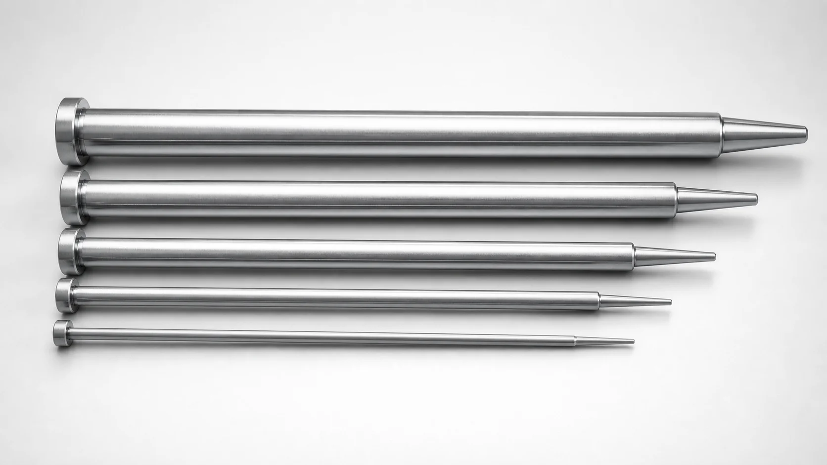
DIN Standard SKD61 Steel One-Step Center Pins
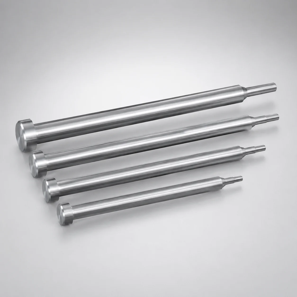
One-Step Center Pins (SKD61 steel) are designed for repeatable mold positioning with a compact one-step geometry. The 4 mm head thickness improves handling and ensures stable seating during setup and operation.
- One-step design for consistent locating and simplified assembly in mold systems
- SKD61 steel construction provides wear resistance under repeated press cycles
- Shaft diameter tolerance options support fit control for sleeve and bushing interfaces
- DIN-standard tooling pins commonly used for center alignment in precision molds
Specifications
1350 configurations available
| Shaft Diameter Tolerance | D/P (Shaft Diameter) (mm) | Step Shape | Tip Shape | Compatible Sleeve Hole Diameter Tolerance | A/V (Tip tolerance) | A (Tip part) (mm) | C (Tip part) (mm) | F (Shaft diameter length) (mm) | G (Tip C chamfering width on the tip part) (mm) | K (Tip part angle) (°) | L (L dimension) (mm) | Q (Tip R chamfering on the tip part) (mm) | R (Tip part) (mm) | S (Tip tapered width on the tip part) (mm) | V (Tip diameter in the tip part) (mm) | type |
|---|---|---|---|---|---|---|---|---|---|---|---|---|---|---|---|---|
| -0.01/-0.02 | 1.5 | A | No processing | +0.01/0 or H7 | ±0.02 | - | - | 50 ~ 199.5 | - | - | 70 ~ 200 | - | - | - | 0.5 ~ 1.49 | - |
| -0.01/-0.02 | 2 | A | No processing | +0.01/0 or H7 | ±0.02 | - | - | 50 ~ 249.5 | - | - | 70 ~ 250 | - | - | - | 0.7 ~ 1.99 | - |
| -0.01/-0.02 | 2.5 | A | No processing | +0.01/0 or H7 | ±0.02 | - | - | 50 ~ 249.5 | - | - | 70 ~ 250 | - | - | - | 0.7 ~ 2.49 | - |
| -0.01/-0.02 | 3 | A | No processing | +0.01/0 or H7 | ±0.02 | - | - | 50 ~ 299.5 | - | - | 70 ~ 300 | - | - | - | 1 ~ 2.99 | - |
| -0.01/-0.02 | 3.5 | A | No processing | +0.01/0 or H7 | ±0.02 | - | - | 50 ~ 299.5 | - | - | 70 ~ 300 | - | - | - | 1 ~ 3.49 | - |
| -0.01/-0.02 | 4 | A | No processing | +0.01/0 or H7 | ±0.02 | - | - | 50 ~ 299.5 | - | - | 70 ~ 300 | - | - | - | 1 ~ 3.99 | - |
| -0.01/-0.02 | 4.5 | A | No processing | +0.01/0 or H7 | ±0.02 | - | - | 50 ~ 299.5 | - | - | 70 ~ 300 | - | - | - | 1.5 ~ 4.49 | - |
| -0.01/-0.02 | 5 | A | No processing | +0.01/0 or H7 | ±0.02 | - | - | 50 ~ 499.5 | - | - | 70 ~ 500 | - | - | - | 1.5 ~ 4.99 | - |
| -0.01/-0.02 | 5.5 | A | No processing | +0.01/0 or H7 | ±0.02 | - | - | 50 ~ 499.5 | - | - | 70 ~ 500 | - | - | - | 2 ~ 5.49 | - |
| -0.01/-0.02 | 6 | A | No processing | +0.01/0 or H7 | ±0.02 | - | - | 50 ~ 499.5 | - | - | 70 ~ 500 | - | - | - | 2 ~ 5.99 | - |
| -0.01/-0.02 | 6.5 | A | No processing | +0.01/0 or H7 | ±0.02 | - | - | 50 ~ 499.5 | - | - | 70 ~ 500 | - | - | - | 2 ~ 6.49 | - |
| -0.01/-0.02 | 7 | A | No processing | +0.01/0 or H7 | ±0.02 | - | - | 50 ~ 499.5 | - | - | 70 ~ 500 | - | - | - | 2 ~ 6.99 | - |
| -0.01/-0.02 | 8 | A | No processing | +0.01/0 or H7 | ±0.02 | - | - | 50 ~ 499.5 | - | - | 70 ~ 500 | - | - | - | 2 ~ 7.99 | - |
| -0.01/-0.02 | 10 | A | No processing | +0.01/0 or H7 | ±0.02 | - | - | 50 ~ 499.5 | - | - | 70 ~ 500 | - | - | - | 2 ~ 9.99 | - |
| -0.01/-0.02 | 12 | A | No processing | +0.01/0 or H7 | ±0.02 | - | - | 50 ~ 499.5 | - | - | 70 ~ 500 | - | - | - | 2 ~ 11.99 | - |
| -0.01/-0.02 | 1.5 | A | B | +0.01/0 or H7 | ±0.02 | - | - | 50 ~ 199.5 | - | - | 70 ~ 200 | - | - | - | 0.5 ~ 1.49 | - |
| -0.01/-0.02 | 2 | A | B | +0.01/0 or H7 | ±0.02 | - | - | 50 ~ 249.5 | - | - | 70 ~ 250 | - | - | - | 0.7 ~ 1.99 | - |
| -0.01/-0.02 | 2.5 | A | B | +0.01/0 or H7 | ±0.02 | - | - | 50 ~ 249.5 | - | - | 70 ~ 250 | - | - | - | 0.7 ~ 2.49 | - |
| -0.01/-0.02 | 3 | A | B | +0.01/0 or H7 | ±0.02 | - | - | 50 ~ 299.5 | - | - | 70 ~ 300 | - | - | - | 1 ~ 2.99 | - |
| -0.01/-0.02 | 3.5 | A | B | +0.01/0 or H7 | ±0.02 | - | - | 50 ~ 299.5 | - | - | 70 ~ 300 | - | - | - | 1 ~ 3.49 | - |
| -0.01/-0.02 | 4 | A | B | +0.01/0 or H7 | ±0.02 | - | - | 50 ~ 299.5 | - | - | 70 ~ 300 | - | - | - | 1 ~ 3.99 | - |
| -0.01/-0.02 | 4.5 | A | B | +0.01/0 or H7 | ±0.02 | - | - | 50 ~ 299.5 | - | - | 70 ~ 300 | - | - | - | 1.5 ~ 4.49 | - |
| -0.01/-0.02 | 5 | A | B | +0.01/0 or H7 | ±0.02 | - | - | 50 ~ 499.5 | - | - | 70 ~ 500 | - | - | - | 1.5 ~ 4.99 | - |
| -0.01/-0.02 | 5.5 | A | B | +0.01/0 or H7 | ±0.02 | - | - | 50 ~ 499.5 | - | - | 70 ~ 500 | - | - | - | 1.5 ~ 5.49 | - |
| -0.01/-0.02 | 6 | A | B | +0.01/0 or H7 | ±0.02 | - | - | 50 ~ 499.5 | - | - | 70 ~ 500 | - | - | - | 2 ~ 5.99 | - |
| -0.01/-0.02 | 6.5 | A | B | +0.01/0 or H7 | ±0.02 | - | - | 50 ~ 499.5 | - | - | 70 ~ 500 | - | - | - | 2 ~ 6.49 | - |
| -0.01/-0.02 | 7 | A | B | +0.01/0 or H7 | ±0.02 | - | - | 50 ~ 499.5 | - | - | 70 ~ 500 | - | - | - | 2 ~ 6.99 | - |
| -0.01/-0.02 | 8 | A | B | +0.01/0 or H7 | ±0.02 | - | - | 50 ~ 499.5 | - | - | 70 ~ 500 | - | - | - | 2 ~ 7.99 | - |
| -0.01/-0.02 | 10 | A | B | +0.01/0 or H7 | ±0.02 | - | - | 50 ~ 499.5 | - | - | 70 ~ 500 | - | - | - | 2 ~ 9.99 | - |
| -0.01/-0.02 | 12 | A | B | +0.01/0 or H7 | ±0.02 | - | - | 50 ~ 499.5 | - | - | 70 ~ 500 | - | - | - | 2 ~ 11.99 | - |
| -0.01/-0.02 | 1.5 | A | C | +0.01/0 or H7 | ±0.02 | - | - | 50 ~ 199.5 | 0.5 ~ 0.7 | - | 70 ~ 200 | - | - | - | 0.5 ~ 1.49 | - |
| -0.01/-0.02 | 2 | A | C | +0.01/0 or H7 | ±0.02 | - | - | 50 ~ 249.5 | 0.5 ~ 0.9 | - | 70 ~ 250 | - | - | - | 0.7 ~ 1.99 | - |
| -0.01/-0.02 | 2.5 | A | C | +0.01/0 or H7 | ±0.02 | - | - | 50 ~ 249.5 | 0.5 ~ 1.2 | - | 70 ~ 250 | - | - | - | 0.7 ~ 2.49 | - |
| -0.01/-0.02 | 3 | A | C | +0.01/0 or H7 | ±0.02 | - | - | 50 ~ 299.5 | 0.5 ~ 1.4 | - | 70 ~ 300 | - | - | - | 1 ~ 2.99 | - |
| -0.01/-0.02 | 3.5 | A | C | +0.01/0 or H7 | ±0.02 | - | - | 50 ~ 299.5 | 0.5 ~ 1.7 | - | 70 ~ 300 | - | - | - | 1 ~ 3.49 | - |
| -0.01/-0.02 | 4 | A | C | +0.01/0 or H7 | ±0.02 | - | - | 50 ~ 299.5 | 0.5 ~ 1.9 | - | 70 ~ 300 | - | - | - | 1 ~ 3.99 | - |
| -0.01/-0.02 | 4.5 | A | C | +0.01/0 or H7 | ±0.02 | - | - | 50 ~ 299.5 | 0.5 ~ 2.2 | - | 70 ~ 300 | - | - | - | 1.5 ~ 4.49 | - |
| -0.01/-0.02 | 5 | A | C | +0.01/0 or H7 | ±0.02 | - | - | 50 ~ 499.5 | 0.5 ~ 2.4 | - | 70 ~ 500 | - | - | - | 1.5 ~ 4.99 | - |
| -0.01/-0.02 | 5.5 | A | C | +0.01/0 or H7 | ±0.02 | - | - | 50 ~ 499.5 | 0.5 ~ 2.7 | - | 70 ~ 500 | - | - | - | 1.5 ~ 5.49 | - |
| -0.01/-0.02 | 6 | A | C | +0.01/0 or H7 | ±0.02 | - | - | 50 ~ 499.5 | 0.5 ~ 2.9 | - | 70 ~ 500 | - | - | - | 2 ~ 5.99 | - |
| -0.01/-0.02 | 6.5 | A | C | +0.01/0 or H7 | ±0.02 | - | - | 50 ~ 499.5 | 0.5 ~ 3.2 | - | 70 ~ 500 | - | - | - | 2 ~ 6.49 | - |
| -0.01/-0.02 | 7 | A | C | +0.01/0 or H7 | ±0.02 | - | - | 50 ~ 499.5 | 0.5 ~ 3.4 | - | 70 ~ 500 | - | - | - | 2 ~ 6.99 | - |
| -0.01/-0.02 | 8 | A | C | +0.01/0 or H7 | ±0.02 | - | - | 50 ~ 499.5 | 0.5 ~ 3.9 | - | 70 ~ 500 | - | - | - | 2 ~ 7.99 | - |
| -0.01/-0.02 | 10 | A | C | +0.01/0 or H7 | ±0.02 | - | - | 50 ~ 499.5 | 0.5 ~ 4.9 | - | 70 ~ 500 | - | - | - | 2 ~ 9.99 | - |
| -0.01/-0.02 | 12 | A | C | +0.01/0 or H7 | ±0.02 | - | - | 50 ~ 499.5 | 0.5 ~ 6.4 | - | 70 ~ 500 | - | - | - | 2 ~ 11.99 | - |
| -0.01/-0.02 | 1.5 | A | G | +0.01/0 or H7 | ±0.02 | - | - | 50 ~ 199.5 | - | 21 ~ 60 | 70 ~ 200 | - | - | - | 0.5 ~ 1.49 | - |
| -0.01/-0.02 | 2 | A | G | +0.01/0 or H7 | ±0.02 | - | - | 50 ~ 249.5 | - | 21 ~ 60 | 70 ~ 250 | - | - | - | 0.7 ~ 1.99 | - |
| -0.01/-0.02 | 2.5 | A | G | +0.01/0 or H7 | ±0.02 | - | - | 50 ~ 249.5 | - | 21 ~ 60 | 70 ~ 250 | - | - | - | 0.7 ~ 2.49 | - |
| -0.01/-0.02 | 3 | A | G | +0.01/0 or H7 | ±0.02 | - | - | 50 ~ 299.5 | - | 21 ~ 60 | 70 ~ 300 | - | - | - | 1 ~ 2.99 | - |
| -0.01/-0.02 | 3.5 | A | G | +0.01/0 or H7 | ±0.02 | - | - | 50 ~ 299.5 | - | 21 ~ 60 | 70 ~ 300 | - | - | - | 1 ~ 3.49 | - |
Product Guide
Application Scenarios+
One-step center pins like this DIN-standard SKD61 variant are used in injection mold tooling wherever repeatable alignment between moving and stationary components is critical. The compact one-step geometry supports consistent seating during mold build-up, helping reduce shift over repeated clamp cycles.
- Automotive connector and housing molds: Use the 1.5–12 mm shaft range to match locating features on ejector-sleeve and bushing interfaces, improving alignment during high-cycle production.
- Precision consumer electronics assemblies: The available tip/tolerance options (e.g., A/V ±0.02 or ±0.01) support controlled pilot engagement for stable positioning during short-run to medium-run molding.
- Medical device component molds: The wear-resistant SKD61 steel construction helps maintain positional accuracy when molded parts require tight dimensional consistency.
The 4 mm head support (per the product description) improves handling and helps ensure reliable contact at assembly, which is especially valuable when pins are installed and removed for troubleshooting or preventive maintenance.
Material & Process Details+
SKD61 is a hot-work tool steel widely used for mold base components requiring wear resistance and strength under cyclic loading. In practice, it is commonly treated as an H13-equivalent alloy (AISI H13 / DIN SKD61 family) depending on supplier grade details.
- Heat treatment: Typically supplied to a quenched & tempered condition for a balance of hardness and toughness in tooling.
- Hardness & performance trade-off: Quenched & tempered SKD61 can be hardened to maintain good wear resistance against fretting/locating loads, while retaining toughness to resist chipping at the tip under repeated press cycles.
- Surface/after-treatment options: For higher wear or longer life, nitriding or similar surface hardening is often applied in tooling systems; however, specific post-treatment is not stated in the provided data.
Compared with softer steels, SKD61’s hardened condition better resists galling and tip wear, supporting stable mold positioning accuracy over time.
Sizing & Selection Guide+
To select the correct center pin dimensions, match both the shaft diameter and the locating engagement geometry to your mold sleeve/bushing holes. This product supports D/P (shaft diameter) = 1.5 ~ 12 mm, with configurable shaft diameter tolerance of -0.01/-0.02, 0/-0.005.
- Choose the shaft diameter and tolerance: Select D/P within 1.5–12 mm, then align the pin tolerance with the compatible sleeve hole diameter tolerance listed as +0.01/0 or H7 and +0.005/0. This controls the fit between pin and sleeve hole.
- Select tip/step style: Pick the required step shape (A–E) and tip shape (No processing, B, C, G, R, T) to achieve the intended pilot contact.
- Verify length and engagement: Use L dimension = 70–200/250/300/400/350/500 mm options to ensure full functional reach for your cavity/core arrangement.
- Tip geometry tolerances: Confirm A/V ±0.02 or ±0.01 plus tip parameters (e.g., A 0.5–2 mm, V 0.5–2.5 mm, R 0.2–0.3 mm) to maintain controlled guidance.
Dimensions listed are configurable within the provided ranges; fixed dimensions apply only to the specific ordering configuration you select.
Frequently Asked Questions
Which shaft diameter tolerance (-0.01/-0.02 or 0/-0.005) should I use for a given sleeve hole tolerance (H7 or +0.01/0)?+
Select the pin’s D/P shaft diameter (1.5–12 mm) and then choose the shaft tolerance that matches your sleeve hole tolerance. This product specifies compatible sleeve hole diameter tolerances of +0.01/0 or H7 and +0.005/0.
For tighter positional control, coordinate the sign and magnitude of the tolerance range so the expected clearance/interference aligns with your pilot engagement requirements.
How do I choose the correct one-step design (step shapes A–E) and tip shapes (B, C, G, R, T) for stable alignment?+
This pin offers step shapes A, B, C, D, E and multiple tip shapes including no processing, B, C, G, R, and T. The selection should reflect the sleeve/bushing interface and the desired pilot contact form.
Confirm that the selected tip tolerance parameters such as A/V (±0.02 or ±0.01) and tip dimensions (e.g., R 0.2–0.3 mm) are compatible with your locating feature geometry.
What length (L) options are available, and how does L affect center pin reach in core/cavity alignment?+
The product provides configurable L dimensions spanning 70–200, 70–250, 70–300, 70–350, 70–400, and 70–500 mm. Choose L to ensure the pin supports functional pilot engagement across the full assembly stack-up between core and cavity.
Verify that the selected L length does not interfere with adjacent components during clamp travel and maintains consistent contact at assembly and operation.
Is the SKD61 DIN one-step center pin suitable for high-cycle mold positioning, and what durability properties matter?+
The pin is made from SKD61 steel, specified for wear resistance under repeated press cycles. Center pins experience cyclic locating loads and tip wear risk, so hardness from the quenched & tempered condition (typical for this steel family) is critical for maintaining alignment.
If you require extended wear life, consider whether your tooling process includes additional surface treatments (not specified in the provided data) after pin selection.
How do I confirm tip geometry tolerances (A/V ±0.02 or ±0.01) when designing the pilot interface?+
This product lists A/V tip tolerance options of ±0.02 or ±0.01. Use the tighter tolerance when your pilot interface requires reduced positional variability and more consistent guidance.
Cross-check the associated tip dimensions (e.g., A = 0.5–2 mm, V = 0.5–2.5 mm, R = 0.2–0.3 mm) to ensure the locating profile matches your sleeve and bushing counter-requirements.
Related Products
Need Custom Specifications?
Our engineering team can help with custom configurations, material selection, and volume pricing.