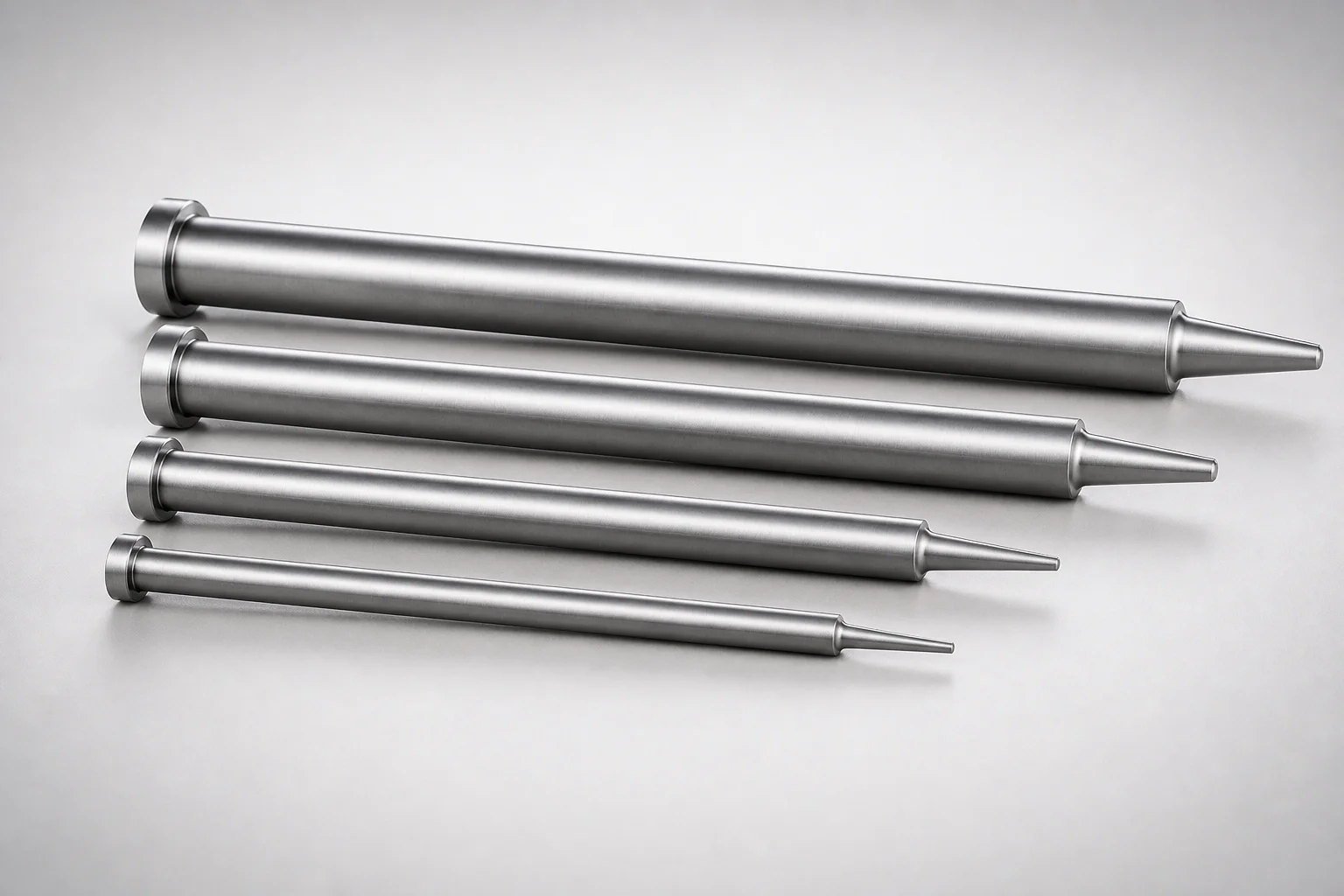
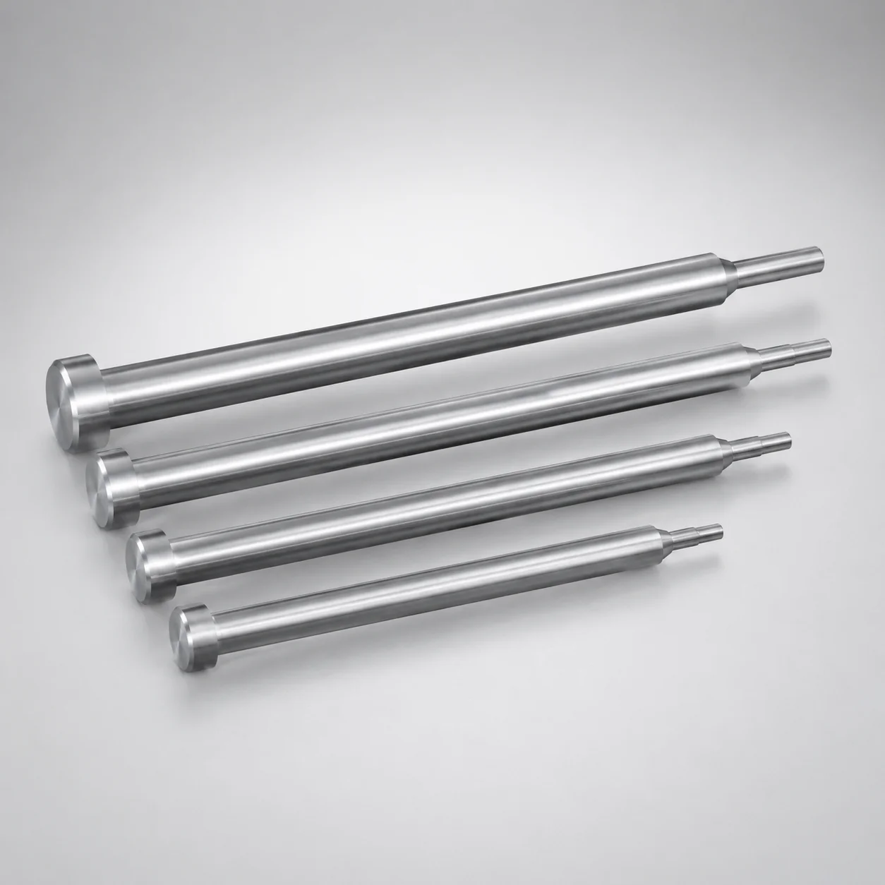
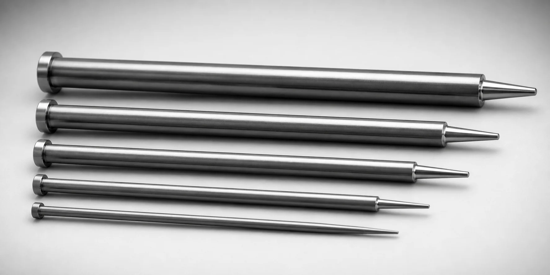
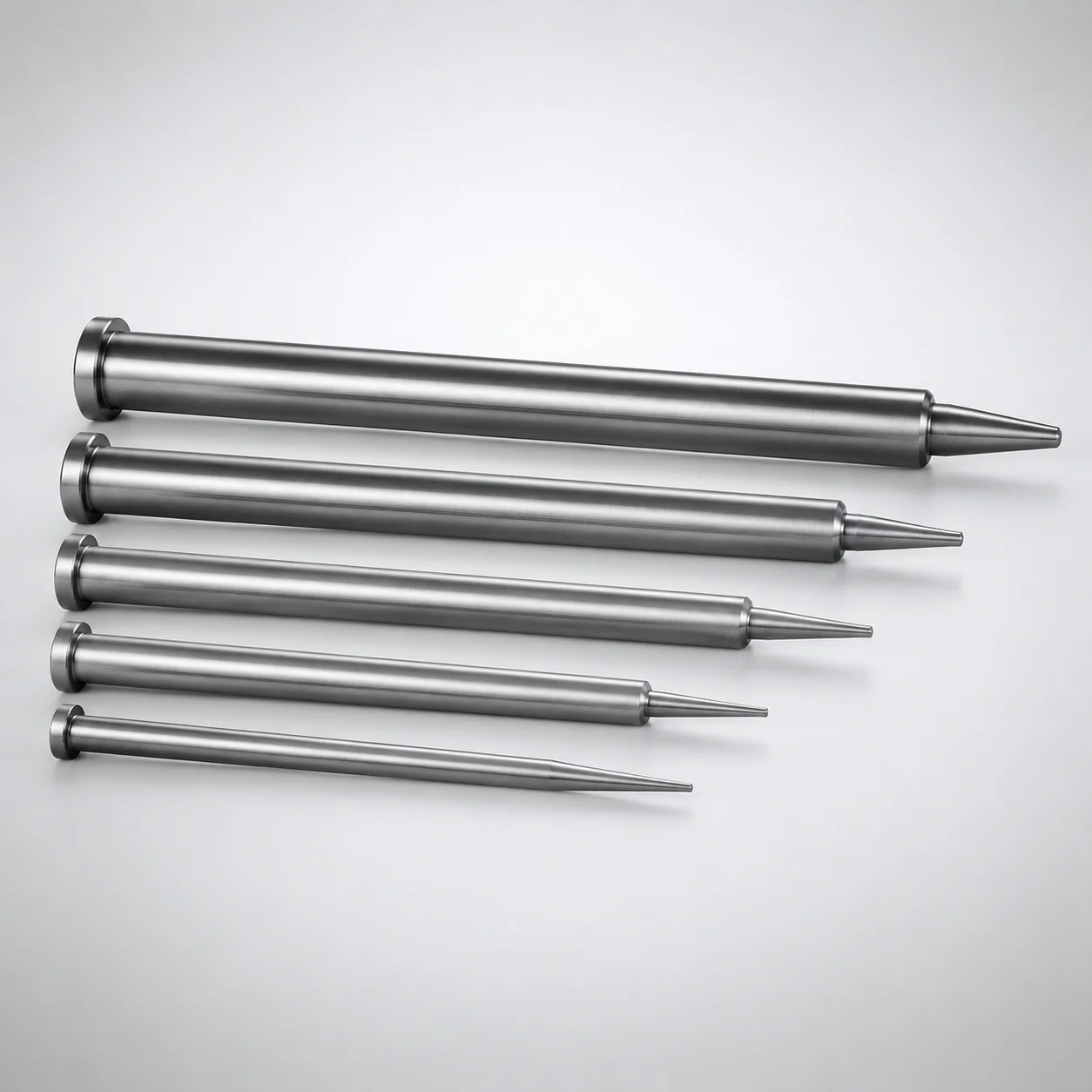
SKD61 Steel One-Step Center Pins One-Step
One-Step Center Pins (SKD61 steel) are engineered for accurate centering in mold assembly, using a one-step geometry that helps maintain positional stability under repeated tool cycles. The 4 mm head provides reliable guidance during installation and alignment.
- One-step center pin shape improves alignment repeatability in mold assembly
- Wear-resistant SKD61 hardened steel construction supports long service life
- 4 mm head (T4) promotes consistent seating and stable guidance
- Built for configurable tip and shaft diameters to match sleeve and bore requirements
Specifications
1350 configurations available
| Shaft Diameter Tolerance | D/P (Shaft Diameter) (mm) | Step Shape | Tip Shape | Compatible Sleeve Hole Diameter Tolerance | A/V (Tip tolerance) | No. (Nominal diameter) (mm) | A (Tip part) (mm) | C (Tip part) (mm) | F (Shaft diameter length) (mm) | G (Tip C chamfering width on the tip part) (mm) | K (Tip part angle) (°) | L (L dimension) (mm) | Q (Tip R chamfering on the tip part) (mm) | R (Tip part) (mm) | S (Tip tapered width on the tip part) (mm) | V (Tip diameter in the tip part) (mm) | type |
|---|---|---|---|---|---|---|---|---|---|---|---|---|---|---|---|---|---|
| -0.01/-0.02 | 1 ~ 1.49 | A | No processing | +0.01/0 or H7 | ±0.02 | 1.5 | - | - | 50 ~ 199.5 | - | - | 70 ~ 200 | - | - | - | 0.5 ~ 1.48 | - |
| -0.01/-0.02 | 1.5 ~ 1.99 | A | No processing | +0.01/0 or H7 | ±0.02 | 2 | - | - | 50 ~ 249.5 | - | - | 70 ~ 250 | - | - | - | 0.7 ~ 1.98 | - |
| -0.01/-0.02 | 2 ~ 2.49 | A | No processing | +0.01/0 or H7 | ±0.02 | 2.5 | - | - | 50 ~ 249.5 | - | - | 70 ~ 250 | - | - | - | 0.7 ~ 2.48 | - |
| -0.01/-0.02 | 2.5 ~ 2.99 | A | No processing | +0.01/0 or H7 | ±0.02 | 3 | - | - | 50 ~ 299.5 | - | - | 70 ~ 300 | - | - | - | 1 ~ 2.98 | - |
| -0.01/-0.02 | 3 ~ 3.49 | A | No processing | +0.01/0 or H7 | ±0.02 | 3.5 | - | - | 50 ~ 299.5 | - | - | 70 ~ 300 | - | - | - | 1 ~ 3.48 | - |
| -0.01/-0.02 | 3.5 ~ 3.99 | A | No processing | +0.01/0 or H7 | ±0.02 | 4 | - | - | 50 ~ 299.5 | - | - | 70 ~ 300 | - | - | - | 1 ~ 3.98 | - |
| -0.01/-0.02 | 4 ~ 4.49 | A | No processing | +0.01/0 or H7 | ±0.02 | 4.5 | - | - | 50 ~ 299.5 | - | - | 70 ~ 300 | - | - | - | 1.5 ~ 4.48 | - |
| -0.01/-0.02 | 4.5 ~ 4.99 | A | No processing | +0.01/0 or H7 | ±0.02 | 5 | - | - | 50 ~ 349.5 | - | - | 70 ~ 350 | - | - | - | 1.5 ~ 4.98 | - |
| -0.01/-0.02 | 5 ~ 5.49 | A | No processing | +0.01/0 or H7 | ±0.02 | 5.5 | - | - | 50 ~ 349.5 | - | - | 70 ~ 350 | - | - | - | 2 ~ 5.48 | - |
| -0.01/-0.02 | 5 ~ 5.99 | A | No processing | +0.01/0 or H7 | ±0.02 | 6 | - | - | 50 ~ 349.5 | - | - | 70 ~ 350 | - | - | - | 2 ~ 5.98 | - |
| -0.01/-0.02 | 6 ~ 6.49 | A | No processing | +0.01/0 or H7 | ±0.02 | 6.5 | - | - | 50 ~ 349.5 | - | - | 70 ~ 350 | - | - | - | 2 ~ 6.48 | - |
| -0.01/-0.02 | 6 ~ 6.99 | A | No processing | +0.01/0 or H7 | ±0.02 | 7 | - | - | 50 ~ 349.5 | - | - | 70 ~ 350 | - | - | - | 2 ~ 6.98 | - |
| -0.01/-0.02 | 6 ~ 7.99 | A | No processing | +0.01/0 or H7 | ±0.02 | 8 | - | - | 50 ~ 349.5 | - | - | 70 ~ 350 | - | - | - | 2 ~ 7.98 | - |
| -0.01/-0.02 | 8 ~ 9.99 | A | No processing | +0.01/0 or H7 | ±0.02 | 10 | - | - | 50 ~ 349.5 | - | - | 70 ~ 350 | - | - | - | 2 ~ 9.98 | - |
| -0.01/-0.02 | 10 ~ 11.99 | A | No processing | +0.01/0 or H7 | ±0.02 | 12 | - | - | 50 ~ 349.5 | - | - | 70 ~ 350 | - | - | - | 2 ~ 11.98 | - |
| -0.01/-0.02 | 1 ~ 1.49 | A | B | +0.01/0 or H7 | ±0.02 | 1.5 | - | - | 50 ~ 199.5 | - | - | 70 ~ 200 | - | - | - | 0.5 ~ 1.49 | - |
| -0.01/-0.02 | 1.5 ~ 1.99 | A | B | +0.01/0 or H7 | ±0.02 | 2 | - | - | 50 ~ 249.5 | - | - | 70 ~ 250 | - | - | - | 0.7 ~ 1.99 | - |
| -0.01/-0.02 | 2 ~ 2.49 | A | B | +0.01/0 or H7 | ±0.02 | 2.5 | - | - | 50 ~ 249.5 | - | - | 70 ~ 250 | - | - | - | 0.7 ~ 2.49 | - |
| -0.01/-0.02 | 2.5 ~ 2.99 | A | B | +0.01/0 or H7 | ±0.02 | 3 | - | - | 50 ~ 299.5 | - | - | 70 ~ 300 | - | - | - | 1 ~ 2.99 | - |
| -0.01/-0.02 | 3 ~ 3.49 | A | B | +0.01/0 or H7 | ±0.02 | 3.5 | - | - | 50 ~ 299.5 | - | - | 70 ~ 300 | - | - | - | 1 ~ 3.49 | - |
| -0.01/-0.02 | 3.5 ~ 3.99 | A | B | +0.01/0 or H7 | ±0.02 | 4 | - | - | 50 ~ 299.5 | - | - | 70 ~ 300 | - | - | - | 1 ~ 3.99 | - |
| -0.01/-0.02 | 4 ~ 4.49 | A | B | +0.01/0 or H7 | ±0.02 | 4.5 | - | - | 50 ~ 299.5 | - | - | 70 ~ 300 | - | - | - | 1.5 ~ 4.49 | - |
| -0.01/-0.02 | 4.5 ~ 4.99 | A | B | +0.01/0 or H7 | ±0.02 | 5 | - | - | 50 ~ 349.5 | - | - | 70 ~ 350 | - | - | - | 1.5 ~ 4.99 | - |
| -0.01/-0.02 | 5 ~ 5.49 | A | B | +0.01/0 or H7 | ±0.02 | 5.5 | - | - | 50 ~ 349.5 | - | - | 70 ~ 350 | - | - | - | 1.5 ~ 5.49 | - |
| -0.01/-0.02 | 5 ~ 5.99 | A | B | +0.01/0 or H7 | ±0.02 | 6 | - | - | 50 ~ 349.5 | - | - | 70 ~ 350 | - | - | - | 2 ~ 5.98 | - |
| -0.01/-0.02 | 6 ~ 6.49 | A | B | +0.01/0 or H7 | ±0.02 | 6.5 | - | - | 50 ~ 349.5 | - | - | 70 ~ 350 | - | - | - | 2 ~ 6.49 | - |
| -0.01/-0.02 | 6 ~ 6.99 | A | B | +0.01/0 or H7 | ±0.02 | 7 | - | - | 50 ~ 349.5 | - | - | 70 ~ 350 | - | - | - | 2 ~ 5.98 | - |
| -0.01/-0.02 | 6 ~ 7.99 | A | B | +0.01/0 or H7 | ±0.02 | 8 | - | - | 50 ~ 349.5 | - | - | 70 ~ 350 | - | - | - | 2 ~ 5.98 | - |
| -0.01/-0.02 | 8 ~ 9.99 | A | B | +0.01/0 or H7 | ±0.02 | 10 | - | - | 50 ~ 349.5 | - | - | 70 ~ 350 | - | - | - | 2 ~ 9.99 | - |
| -0.01/-0.02 | 10 ~ 11.99 | A | B | +0.01/0 or H7 | ±0.02 | 12 | - | - | 50 ~ 349.5 | - | - | 70 ~ 350 | - | - | - | 2 ~ 11.99 | - |
| -0.01/-0.02 | 1 ~ 1.49 | A | C | +0.01/0 or H7 | ±0.02 | 1.5 | - | - | 50 ~ 199.5 | 0.5 ~ 0.7 | - | 70 ~ 200 | - | - | - | 0.5 ~ 1.49 | - |
| -0.01/-0.02 | 1.5 ~ 1.99 | A | C | +0.01/0 or H7 | ±0.02 | 2 | - | - | 50 ~ 249.5 | 0.5 ~ 0.9 | - | 70 ~ 250 | - | - | - | 0.7 ~ 1.99 | - |
| -0.01/-0.02 | 2 ~ 2.49 | A | C | +0.01/0 or H7 | ±0.02 | 2.5 | - | - | 50 ~ 249.5 | 0.5 ~ 1.2 | - | 70 ~ 250 | - | - | - | 0.7 ~ 2.49 | - |
| -0.01/-0.02 | 2.5 ~ 2.99 | A | C | +0.01/0 or H7 | ±0.02 | 3 | - | - | 50 ~ 299.5 | 0.5 ~ 1.4 | - | 70 ~ 300 | - | - | - | 1 ~ 2.99 | - |
| -0.01/-0.02 | 3 ~ 3.49 | A | C | +0.01/0 or H7 | ±0.02 | 3.5 | - | - | 50 ~ 299.5 | 0.5 ~ 1.7 | - | 70 ~ 300 | - | - | - | 1 ~ 3.49 | - |
| -0.01/-0.02 | 3.5 ~ 3.99 | A | C | +0.01/0 or H7 | ±0.02 | 4 | - | - | 50 ~ 299.5 | 0.5 ~ 1.9 | - | 70 ~ 300 | - | - | - | 1 ~ 3.99 | - |
| -0.01/-0.02 | 4 ~ 4.49 | A | C | +0.01/0 or H7 | ±0.02 | 4.5 | - | - | 50 ~ 299.5 | 0.5 ~ 2.2 | - | 70 ~ 300 | - | - | - | 1.5 ~ 4.49 | - |
| -0.01/-0.02 | 4.5 ~ 4.99 | A | C | +0.01/0 or H7 | ±0.02 | 5 | - | - | 50 ~ 349.5 | 0.5 ~ 2.4 | - | 70 ~ 350 | - | - | - | 1.5 ~ 4.99 | - |
| -0.01/-0.02 | 5 ~ 5.49 | A | C | +0.01/0 or H7 | ±0.02 | 5.5 | - | - | 50 ~ 349.5 | 0.5 ~ 2.7 | - | 70 ~ 350 | - | - | - | 1.5 ~ 5.49 | - |
| -0.01/-0.02 | 5 ~ 5.99 | A | C | +0.01/0 or H7 | ±0.02 | 6 | - | - | 50 ~ 349.5 | 0.5 ~ 2.9 | - | 70 ~ 350 | - | - | - | 2 ~ 5.98 | - |
| -0.01/-0.02 | 6 ~ 6.49 | A | C | +0.01/0 or H7 | ±0.02 | 6.5 | - | - | 50 ~ 349.5 | 0.5 ~ 3.2 | - | 70 ~ 350 | - | - | - | 2 ~ 6.49 | - |
| -0.01/-0.02 | 6 ~ 6.99 | A | C | +0.01/0 or H7 | ±0.02 | 7 | - | - | 50 ~ 349.5 | 0.5 ~ 2.9 | - | 70 ~ 350 | - | - | - | 2 ~ 5.98 | - |
| -0.01/-0.02 | 6 ~ 7.99 | A | C | +0.01/0 or H7 | ±0.02 | 8 | - | - | 50 ~ 349.5 | 0.5 ~ 2.9 | - | 70 ~ 350 | - | - | - | 2 ~ 5.98 | - |
| -0.01/-0.02 | 8 ~ 9.99 | A | C | +0.01/0 or H7 | ±0.02 | 10 | - | - | 50 ~ 349.5 | 0.5 ~ 4.9 | - | 70 ~ 350 | - | - | - | 2 ~ 9.99 | - |
| -0.01/-0.02 | 10 ~ 11.99 | A | C | +0.01/0 or H7 | ±0.02 | 12 | - | - | 50 ~ 349.5 | 0.5 ~ 6.4 | - | 70 ~ 350 | - | - | - | 2 ~ 11.99 | - |
| -0.01/-0.02 | 1 ~ 1.49 | A | G | +0.01/0 or H7 | ±0.02 | 1.5 | - | - | 50 ~ 199.5 | - | 21 ~ 60 | 70 ~ 200 | - | - | - | 0.5 ~ 1.49 | - |
| -0.01/-0.02 | 1.5 ~ 1.99 | A | G | +0.01/0 or H7 | ±0.02 | 2 | - | - | 50 ~ 249.5 | - | 21 ~ 60 | 70 ~ 250 | - | - | - | 0.7 ~ 1.99 | - |
| -0.01/-0.02 | 2 ~ 2.49 | A | G | +0.01/0 or H7 | ±0.02 | 2.5 | - | - | 50 ~ 249.5 | - | 21 ~ 60 | 70 ~ 250 | - | - | - | 0.7 ~ 2.49 | - |
| -0.01/-0.02 | 2.5 ~ 2.99 | A | G | +0.01/0 or H7 | ±0.02 | 3 | - | - | 50 ~ 299.5 | - | 21 ~ 60 | 70 ~ 300 | - | - | - | 1 ~ 2.99 | - |
| -0.01/-0.02 | 3 ~ 3.49 | A | G | +0.01/0 or H7 | ±0.02 | 3.5 | - | - | 50 ~ 299.5 | - | 21 ~ 60 | 70 ~ 300 | - | - | - | 1 ~ 3.49 | - |
Product Guide
Application Scenarios+
One-step center pins support precise self-centering during mold assembly, especially where repeated tool cycles can amplify misalignment. The 4 mm head acts as a stable guidance feature, helping operators seat the pin consistently before the cavity/core halves fully close.
- Automotive connector and bracket molds: Use the configurable tip/step geometries to match sleeve and bore requirements, improving alignment repeatability under high-cycle production.
- Appliance and housings with thin-wall cores: The hardened SKD61 steel resists fretting wear at the guidance interfaces, maintaining centering stability as parts cycle rapidly.
- Medical device housing tooling: The one-step geometry supports repeatable positioning, reducing variation in assembly alignment that can affect cosmetic or functional features.
With selection ranges for shaft diameter (D/P 1–10 mm) and head-supported seating (4 mm head / T4), this variant is suited for designs needing stable centering without complex multi-step alignment features.
Material & Process Details+
The center pin is manufactured from SKD61, a hot-work tool steel commonly aligned to AISI H13 class performance for mold tooling applications. In injection mold service, SKD61 provides a balance of wear resistance at guidance interfaces and toughness for repeated assembly and ejection cycles.
- Hardness & wear: Typical hardened-and-tempered service conditions target stable HRC for sliding/contact guidance, supporting long life against fretting and wear.
- Toughness trade-off: Higher hardness improves wear resistance, while excessive hardness can reduce impact toughness during assembly; tempered conditions are used to recover toughness.
- Heat treatment state: Generally supplied in a hardened & tempered form for dimensional stability and consistent performance.
- Material comparison: Compared with lower-alloy steels, SKD61 better withstands contact wear and cyclic loading; compared with higher-wear tool steels, it offers a practical toughness/wear balance for center guidance.
Specific hardness depends on the delivered heat treatment condition and final selection.
Sizing & Selection Guide+
To select the correct stepped one-step center pin, start by matching the shaft diameter to the intended sleeve hole and guidance bore. For this product, the D/P (shaft diameter) is specified in the range 1 ~ 10 mm, with a shaft diameter tolerance of -0.01/-0.02, 0/-0.005.
- Sleeve compatibility: Choose a pin whose shaft diameter fits the compatible sleeve hole diameter tolerance of +0.01/0 or H7 or +0.005/0. This ensures controlled guidance without excessive clearance.
- Nominal diameter and step geometry: Confirm the nominal diameter No. 1.5 ~ 12 mm and select the step shape (A–E) and tip shape (No processing, B, C, G, R, T) that fit the sleeve/bore profile.
- Length matching: Validate the L dimension selection (e.g., 70–200 up to 70–500 variants) for tool thickness and engagement depth.
When configured, tip geometry tolerances (e.g., A/V ±0.02 or ±0.01) should be checked against the mating sleeve’s machining tolerance to maintain centering precision and avoid binding during assembly.
Frequently Asked Questions
Which shaft diameter range (D/P) and tolerance should I use for this one-step center pin?+
The D/P (shaft diameter) range is 1 ~ 10 mm. The shaft diameter tolerance is provided as -0.01/-0.02, 0/-0.005. Select the pin so the mating sleeve hole tolerance matches the listed compatible sleeve hole tolerance options (including H7 where applicable).
How do I ensure the pin’s guidance fit with the compatible sleeve hole diameter tolerance?+
Use the provided sleeve hole tolerance compatibility: +0.01/0 or H7 and +0.005/0. Match the pin’s configured D/P to the sleeve’s finished hole size within those tolerance bands. This helps maintain alignment without excessive play that could degrade centering repeatability.
What should I choose for step shape (A–E) and tip shape to match my mold sleeve/bore geometry?+
This product supports step shapes A, B, C, D, E and tip shapes including No processing, B, C, G, R, T. Choose the combination that corresponds to your sleeve engagement profile and desired centering behavior. Also verify tip geometry parameters (such as C = 0.1 ~ 1.5 mm) and tip tolerances (A/V ±0.02 or ±0.01).
How do I select the overall L dimension (70–200/250/300/350/500) for correct engagement?+
Select L based on required engagement depth across the mold assembly thickness. Available ranges are listed as 70 ~ 200, 70 ~ 250, 70 ~ 300, 70 ~ 350, and 70 ~ 500. Confirm that L provides full guidance seating while avoiding interference during closing.
What material and heat treatment performance should I expect from SKD61 for repeated mold assembly alignment?+
The pin is made from SKD61 (commonly associated with AISI H13 class tool steel). It is designed for hardened-and-tempered service conditions to deliver wear resistance at the guidance/contact areas while maintaining toughness for cyclic assembly. Final hardness/HRC depends on the delivered heat treatment state, but the intended outcome is stable guidance under repeated tool cycles.
Related Products
Need Custom Specifications?
Our engineering team can help with custom configurations, material selection, and volume pricing.