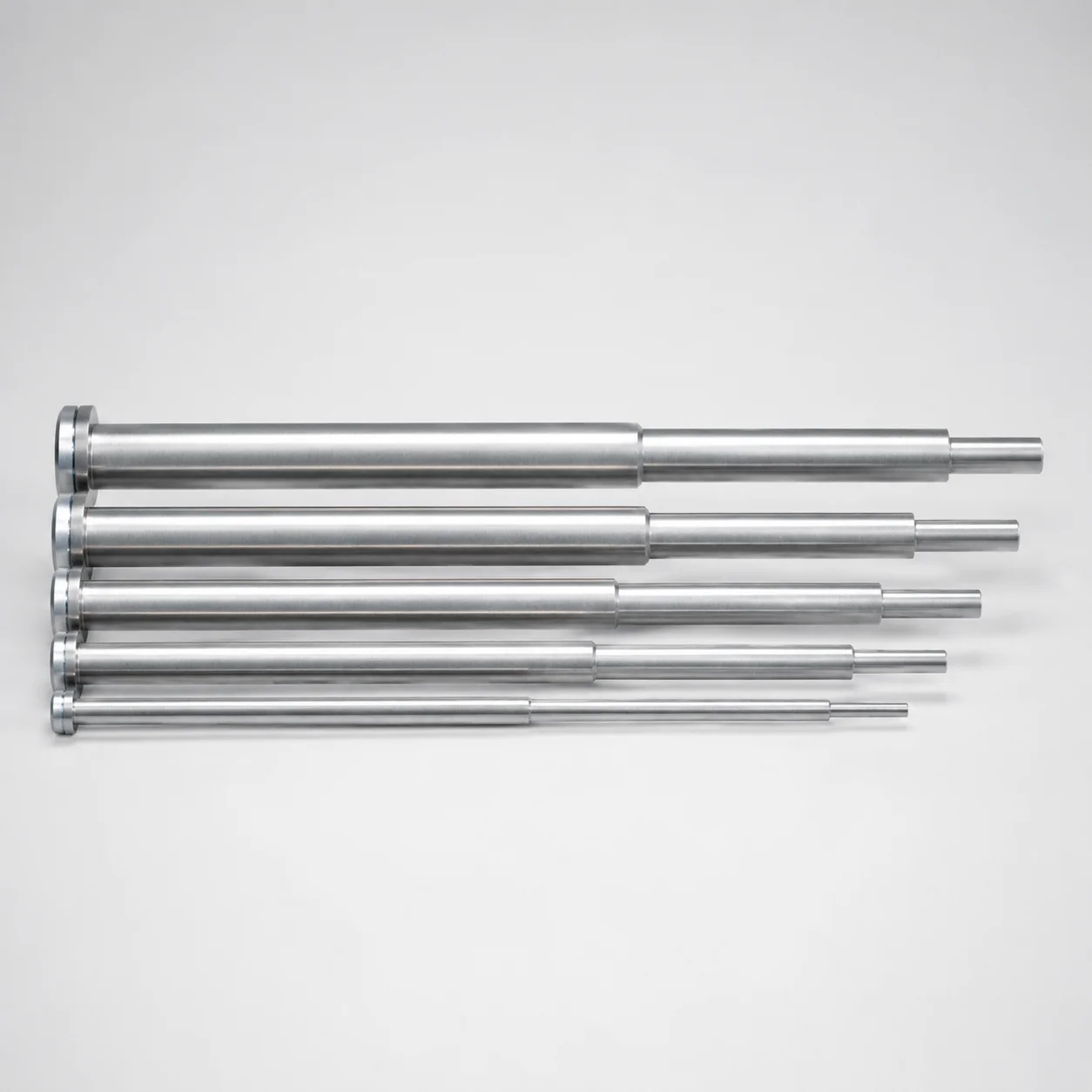
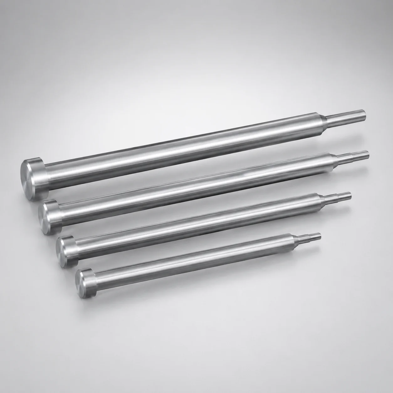
JIS Standard M2 Steel Stepped One-Step Center Pins
Stepped one-step center pins (M2 steel) are designed for repeatable mold alignment, using a stepped one-piece center structure that improves locating stability in assembly. The JIS-based construction supports consistent fit with corresponding mold components.
- Stepped one-step geometry provides stable center positioning during mold closure
- Manufactured from M2 steel for wear-resistant performance in tooling use
- Ground tolerances support controlled pin-to-sleeve fit for reliable alignment repeatability
- JIS standard center pin design for compatibility with standard mold fabrication
Specifications
336 configurations available
| Head Thickness | D/P (Shaft Diameter) (mm) | Step Shape | A/V (Tip tolerance) | D (Stepped root part diameter) (mm) | A (Tip part) (mm) | C (Tip part) (mm) | F (Shaft diameter length) (mm) | L (L dimension) (mm) | Dimension N (mm) | R (Tip part) (mm) | V (Tip diameter in the tip part) (mm) | type |
|---|---|---|---|---|---|---|---|---|---|---|---|---|
| 4mm(T4) | 0.8 ~ 0.99 | A | ±0.01 | 1 | - | - | 55 ~ 149.5 | 70 ~ 200 | 25 ~ 119.9 | - | 0.5 ~ 0.99 | - |
| 4mm(T4) | 1 ~ 1.49 | A | ±0.01 | 1.5 | - | - | 55 ~ 249.5 | 70 ~ 250 | 25 ~ 169.5 | - | 0.5 ~ 1.48 | - |
| 4mm(T4) | 1.5 ~ 1.99 | A | ±0.01 | 2 | - | - | 55 ~ 249.5 | 70 ~ 250 | 25 ~ 219.5 | - | 0.7 ~ 1.98 | - |
| 4mm(T4) | 1.5 ~ 2.49 | A | ±0.01 | 2.5 | - | - | 55 ~ 249.5 | 70 ~ 250 | 25 ~ 219.5 | - | 0.7 ~ 2.48 | - |
| 4mm(T4) | 2 ~ 2.99 | A | ±0.01 | 3 | - | - | 55 ~ 299.5 | 70 ~ 300 | 25 ~ 269.5 | - | 1 ~ 2.99 | - |
| 4mm(T4) | 2.5 ~ 3.49 | A | ±0.01 | 3.5 | - | - | 55 ~ 299.5 | 70 ~ 300 | 25 ~ 269.5 | - | 1 ~ 3.48 | - |
| 4mm(T4) | 3 ~ 3.99 | A | ±0.01 | 4 | - | - | 55 ~ 299.5 | 70 ~ 300 | 25 ~ 269.5 | - | 1 ~ 3.98 | - |
| 4mm(T4) | 3.5 ~ 4.49 | A | ±0.01 | 4.5 | - | - | 55 ~ 299.5 | 70 ~ 300 | 25 ~ 259.5 | - | 1.5 ~ 4.48 | - |
| 4mm(T4) | 4 ~ 4.99 | A | ±0.01 | 5 | - | - | 55 ~ 349.5 | 70 ~ 350 | 25 ~ 319.5 | - | 1.5 ~ 4.98 | - |
| 4mm(T4) | 5 ~ 5.49 | A | ±0.01 | 5.5 | - | - | 55 ~ 349.5 | 70 ~ 350 | 25 ~ 319.5 | - | 2 ~ 5.48 | - |
| 4mm(T4) | 5 ~ 5.99 | A | ±0.01 | 6 | - | - | 55 ~ 349.5 | 70 ~ 350 | 25 ~ 319.5 | - | 2 ~ 5.98 | - |
| 4mm(T4) | 5 ~ 6.49 | A | ±0.01 | 6.5 | - | - | 55 ~ 349.5 | 70 ~ 350 | 25 ~ 319.5 | - | 2 ~ 6.48 | - |
| 4mm(T4) | 6 ~ 6.99 | A | ±0.01 | 7 | - | - | 55 ~ 349.5 | 70 ~ 350 | 25 ~ 319.5 | - | 2 ~ 6.98 | - |
| 4mm(T4) | 6 ~ 7.99 | A | ±0.01 | 8 | - | - | 55 ~ 349.5 | 70 ~ 350 | 25 ~ 319.5 | - | 2 ~ 7.98 | - |
| 4mm(T4) | 8 ~ 8.99 | A | ±0.01 | 9 | - | - | 55 ~ 349.5 | 70 ~ 350 | 25 ~ 319.5 | - | 2 ~ 8.98 | - |
| 4mm(T4) | 8 ~ 9.99 | A | ±0.01 | 10 | - | - | 55 ~ 349.5 | 70 ~ 350 | 25 ~ 319.5 | - | 2 ~ 9.98 | - |
| 4mm(T4) | 10 ~ 11.99 | A | ±0.01 | 12 | - | - | 55 ~ 349.5 | 70 ~ 350 | 25 ~ 319.5 | - | 2 ~ 11.98 | - |
| 4mm(T4) | 0.8 ~ 0.99 | B | ±0.01 | 1 | 0.5 ~ 0.98 | - | 55 ~ 149.3 | 70 ~ 200 | 25 ~ 119.9 | - | 0.5 ~ 0.99 | - |
| 4mm(T4) | 1 ~ 1.49 | B | ±0.01 | 1.5 | 0.5 ~ 1.48 | - | 55 ~ 249.3 | 70 ~ 250 | 25 ~ 169.3 | - | 0.5 ~ 1.48 | - |
| 4mm(T4) | 1.5 ~ 1.99 | B | ±0.01 | 2 | 0.7 ~ 1.98 | - | 55 ~ 249.3 | 70 ~ 250 | 25 ~ 219.3 | - | 0.7 ~ 1.98 | - |
| 4mm(T4) | 1.5 ~ 2.49 | B | ±0.01 | 2.5 | 0.7 ~ 2.48 | - | 55 ~ 249.3 | 70 ~ 250 | 25 ~ 219.3 | - | 0.7 ~ 2.48 | - |
| 4mm(T4) | 2 ~ 2.99 | B | ±0.01 | 3 | 1 ~ 2.99 | - | 55 ~ 299.3 | 70 ~ 300 | 25 ~ 269.3 | - | 1 ~ 2.99 | - |
| 4mm(T4) | 2.5 ~ 3.49 | B | ±0.01 | 3.5 | 1 ~ 3.48 | - | 55 ~ 299.3 | 70 ~ 300 | 25 ~ 269.3 | - | 1 ~ 3.48 | - |
| 4mm(T4) | 3 ~ 3.99 | B | ±0.01 | 4 | 1 ~ 3.98 | - | 55 ~ 299.3 | 70 ~ 300 | 25 ~ 269.3 | - | 1 ~ 3.98 | - |
| 4mm(T4) | 3.5 ~ 4.49 | B | ±0.01 | 4.5 | 1.5 ~ 4.48 | - | 55 ~ 299.3 | 70 ~ 300 | 25 ~ 259.3 | - | 1.5 ~ 4.48 | - |
| 4mm(T4) | 4 ~ 4.99 | B | ±0.01 | 5 | 1.5 ~ 4.98 | - | 55 ~ 349.3 | 70 ~ 350 | 25 ~ 319.3 | - | 1.5 ~ 4.98 | - |
| 4mm(T4) | 5 ~ 5.49 | B | ±0.01 | 5.5 | 2 ~ 5.48 | - | 55 ~ 349.3 | 70 ~ 350 | 25 ~ 319.3 | - | 2 ~ 5.48 | - |
| 4mm(T4) | 5 ~ 5.99 | B | ±0.01 | 6 | 2 ~ 5.98 | - | 55 ~ 349.3 | 70 ~ 350 | 25 ~ 319.3 | - | 2 ~ 5.98 | - |
| 4mm(T4) | 5 ~ 6.49 | B | ±0.01 | 6.5 | 2 ~ 6.48 | - | 55 ~ 349.3 | 70 ~ 350 | 25 ~ 319.3 | - | 2 ~ 6.48 | - |
| 4mm(T4) | 6 ~ 6.99 | B | ±0.01 | 7 | 2 ~ 6.98 | - | 55 ~ 349.3 | 70 ~ 350 | 25 ~ 319.3 | - | 2 ~ 6.98 | - |
| 4mm(T4) | 6 ~ 7.99 | B | ±0.01 | 8 | 2 ~ 7.98 | - | 55 ~ 349.3 | 70 ~ 350 | 25 ~ 319.3 | - | 2 ~ 7.98 | - |
| 4mm(T4) | 8 ~ 8.99 | B | ±0.01 | 9 | 2 ~ 8.98 | - | 55 ~ 349.3 | 70 ~ 350 | 25 ~ 319.3 | - | 2 ~ 8.98 | - |
| 4mm(T4) | 8 ~ 9.99 | B | ±0.01 | 10 | 2 ~ 9.98 | - | 55 ~ 349.3 | 70 ~ 350 | 25 ~ 319.3 | - | 2 ~ 9.98 | - |
| 4mm(T4) | 10 ~ 11.99 | B | ±0.01 | 12 | 2 ~ 11.98 | - | 55 ~ 349.3 | 70 ~ 350 | 25 ~ 319.3 | - | 2 ~ 11.98 | - |
| 4mm(T4) | 0.8 ~ 0.99 | C | ±0.01 | 1 | 0.5 ~ 0.98 | - | 55 ~ 149.5 | 70 ~ 200 | 25 ~ 119.9 | - | 0.5 ~ 0.99 | - |
| 4mm(T4) | 1 ~ 1.49 | C | ±0.01 | 1.5 | 0.5 ~ 1.48 | - | 55 ~ 199.49 | 70 ~ 250 | 25 ~ 169.4 | - | 0.5 ~ 1.48 | - |
| 4mm(T4) | 1.5 ~ 1.99 | C | ±0.01 | 2 | 0.7 ~ 1.98 | - | 55 ~ 249.49 | 70 ~ 250 | 25 ~ 219.4 | - | 0.7 ~ 1.98 | - |
| 4mm(T4) | 1.5 ~ 2.49 | C | ±0.01 | 2.5 | 0.7 ~ 2.48 | - | 55 ~ 249.49 | 70 ~ 250 | 25 ~ 219.4 | - | 0.7 ~ 2.48 | - |
| 4mm(T4) | 2 ~ 2.99 | C | ±0.01 | 3 | 1 ~ 2.99 | - | 55 ~ 299.49 | 70 ~ 300 | 25 ~ 269.4 | - | 1 ~ 2.99 | - |
| 4mm(T4) | 2.5 ~ 3.49 | C | ±0.01 | 3.5 | 1 ~ 3.48 | - | 55 ~ 299.49 | 70 ~ 300 | 25 ~ 269.4 | - | 1 ~ 3.48 | - |
| 4mm(T4) | 3 ~ 3.99 | C | ±0.01 | 4 | 1 ~ 3.98 | - | 55 ~ 299.49 | 70 ~ 300 | 25 ~ 269.4 | - | 1 ~ 3.98 | - |
| 4mm(T4) | 3.5 ~ 4.49 | C | ±0.01 | 4.5 | 1.5 ~ 4.48 | - | 55 ~ 299.49 | 70 ~ 300 | 25 ~ 259.4 | - | 1.5 ~ 4.48 | - |
| 4mm(T4) | 4 ~ 4.99 | C | ±0.01 | 5 | 1.5 ~ 4.98 | - | 55 ~ 349.49 | 70 ~ 350 | 25 ~ 319.4 | - | 1.5 ~ 4.98 | - |
| 4mm(T4) | 5 ~ 5.49 | C | ±0.01 | 5.5 | 2 ~ 5.48 | - | 55 ~ 349.49 | 70 ~ 350 | 25 ~ 319.4 | - | 2 ~ 5.48 | - |
| 4mm(T4) | 5 ~ 5.99 | C | ±0.01 | 6 | 2 ~ 5.98 | - | 55 ~ 349.49 | 70 ~ 350 | 25 ~ 319.4 | - | 2 ~ 5.98 | - |
| 4mm(T4) | 5 ~ 6.49 | C | ±0.01 | 6.5 | 2 ~ 6.48 | - | 55 ~ 349.49 | 70 ~ 350 | 25 ~ 319.4 | - | 2 ~ 6.48 | - |
| 4mm(T4) | 6 ~ 6.99 | C | ±0.01 | 7 | 2 ~ 6.98 | - | 55 ~ 349.49 | 70 ~ 350 | 25 ~ 319.4 | - | 2 ~ 6.98 | - |
| 4mm(T4) | 6 ~ 7.99 | C | ±0.01 | 8 | 2 ~ 7.98 | - | 55 ~ 349.49 | 70 ~ 350 | 25 ~ 319.4 | - | 2 ~ 7.98 | - |
| 4mm(T4) | 8 ~ 8.99 | C | ±0.01 | 9 | 2 ~ 8.98 | - | 55 ~ 349.49 | 70 ~ 350 | 25 ~ 319.4 | - | 2 ~ 8.98 | - |
| 4mm(T4) | 8 ~ 9.99 | C | ±0.01 | 10 | 2 ~ 9.98 | - | 55 ~ 349.49 | 70 ~ 350 | 25 ~ 319.4 | - | 2 ~ 9.98 | - |
Product Guide
Application Scenarios+
Stepped one-step center pins are used in injection mold tooling wherever repeatable alignment between the moving and fixed halves is critical. In automotive connector and sensor housing molds, these pins help stabilize centering during high-cycle mold closure, reducing misalignment that can drive flash or intermittent parting-line variation.
In medical device housings and dispenser components, the stepped geometry supports consistent locating in automated assembly, helping maintain concentricity around fine features while reducing the risk of wear-through at the guiding interface.
- One-step locating supports stable center positioning during mold closure, improving alignment repeatability.
- M2 steel construction provides durable, wear-resistant performance for frequent cycling.
- Ground tip tolerance (A/V: ±0.01 or ±0.005) supports controlled pin-to-sleeve fit for reliable centering.
Material & Process Details+
This variant is manufactured from JIS M2 steel, commonly selected for cutting-tool style wear resistance in mold components that experience repetitive sliding/locating contact.
- Hardness & wear–toughness balance: M2 is typically hardened to high levels (often in the HRC range used for wear-critical tooling). Higher hardness improves scuff and fretting resistance, while requiring attention to toughness when designing for shock loads.
- Heat treatment state: precision center pins are commonly supplied in a hardened condition with subsequent tempering to stabilize dimensions and reduce brittleness; final grinding then establishes the locating tolerances.
- Manufacturing process: step and tip geometries are machined and finished with grinding to achieve the listed tip tolerance targets.
If alternate tool steels are used in other center-pin families, the key trade-off is usually wear resistance vs. toughness. The M2 selection prioritizes durable locating behavior under repeated cycling.
Sizing & Selection Guide+
Select the pin geometry by matching the locating interfaces to the corresponding mold sleeve and pocket dimensions. Start with the shaft diameter (D/P) in the range 0.8 ~ 10 mm, then verify the required stepped root diameter (D) in 1 ~ 12 mm and the tip part diameter (A) in 0.5 ~ 2 mm.
Next choose the tip/step configuration using the available step shapes (A, B, C, D, E) and ensure the tip size meets the constraint C (fixed): 0.1 ~ 1.5 mm, plus the listed radius R: 0.3 mm. For tolerance-critical centering, pick the A/V tip tolerance grade: ±0.01 or ±0.005.
- Verify shaft length F of 50 ~ 55 mm.
- Select overall L to suit the mold thickness and clearance needs: 70 ~ 200 / 70 ~ 250 / 70 ~ 300 / 70 ~ 350 mm.
- Confirm head thickness T4/JIS options: 4 mm (T4), 4/6/8 mm (JIS) and ensure assembly clearance.
Ground tolerances influence the pin-to-sleeve fit; when switching between ±0.01 and ±0.005, verify the sleeve bore tolerance and press/locating method for stable alignment without binding.
Frequently Asked Questions
How do I choose the correct shaft diameter (D/P) and stepped root diameter (D) for mating sleeves?+
What tip tolerance grade should I use: A/V ±0.01 or ±0.005?+
How does the step shape (A, B, C, D, E) affect alignment behavior in a one-step center pin?+
How should I select overall length (L) and head thickness (T4/JIS) to prevent interference?+
What are the key sizing parameters around the tip, including A, C, and radius R?+
Related Products
Need Custom Specifications?
Our engineering team can help with custom configurations, material selection, and volume pricing.