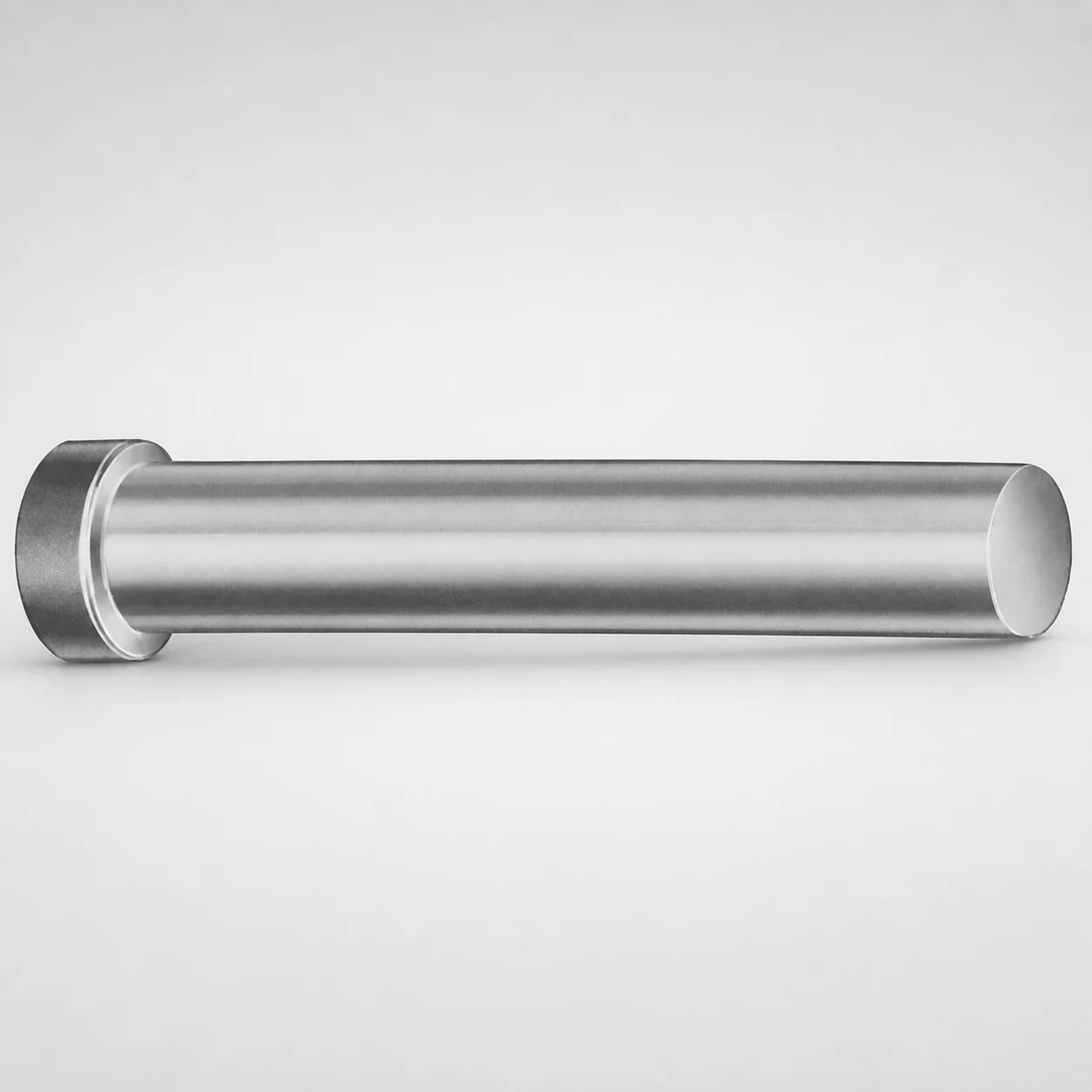
Straight Regular Punches Inch (XNAD Coating)
Straight Regular Punches Inch (XNAD Coating) are designed for stable, repeatable punching performance in forming and blanking operations, with a coating system that supports longer tool life.
- Straight punch geometry for consistent alignment in standard inch tooling
- XNAD coating helps reduce wear and improves cutting edge durability
- Built for controlled length and P-dimension configurations to match press requirements
- Suitable for general fabrication where reliable punch life and stable output matter
Specifications
1 configurations available
| L (Length) (in) | P Dimension (in) |
|---|---|
| 150 ~ 625 | 0.125 ~ 0.375 |
Product Guide
Application Scenarios+
These straight regular punches are used in production-grade injection and forming tooling where high repeatability punching is required, especially for operations such as blanking, piercing, and forming pre-features that later support molded assembly components.
- Automotive connector and bracket tooling: The straight geometry supports consistent alignment within standard inch press setups, helping maintain stable hole location as cycle counts increase. The XNAD coating helps control edge wear for longer punch life.
- Appliance and electronics sheet fabrication: Use when maintaining cutting edge integrity is critical to reduce dimensional drift across runs. The controlled P-dimension configuration supports predictable strip handling and press repeatability.
- General fabrication runs: Suited for applications where reliable punch life and stable output are valued over highly specialized micro-punch requirements.
With lengths in the 150–625 in range and a P dimension of 0.125–0.375 in, this variant can be matched to common press configurations to support consistent, accurate punching performance.
Material & Process Details+
The provided specification focuses on dimensional ranges and the XNAD coating performance layer, rather than a specific steel grade or heat-treatment state. As such, material-selection claims (e.g., exact hardness HRC, quenched-and-tempered condition, or nitriding) cannot be stated from the available data.
For coated punch applications, the engineering intent is typically to improve wear resistance at the cutting edge and help preserve dimensional accuracy during high-cycle production. The XNAD coating supports longer tool life by reducing abrasive and adhesive wear mechanisms.
- Coating-first durability: Expect the main durability benefits to come from the XNAD surface system.
- Toughness trade-off: Coatings generally improve surface performance while core toughness still governs resistance to chipping under misalignment or shock loads.
If you need confirmed steel grade, target hardness (HRC), or a specific heat-treatment route for your build standard, share your drawing requirements and we can align the specification accordingly.
Sizing & Selection Guide+
Select the correct punch size by matching both L (Length) and the P dimension to your press tooling stack-up and the intended piercing depth/engagement profile.
- Length (L): Choose a fixed L within 150–625 in based on your press opening, holder/projection requirements, and the required penetration depth for the formed feature.
- P dimension: Select P in the range 0.125–0.375 in to match the configured press interface and the geometry relationship your tooling uses for alignment and engagement.
To minimize positional variation, ensure the selected dimensions are consistent with the core/cavity interaction equivalent in your die set—where the punch’s alignment and engagement determine hole location and size stability. If your drawing specifies tight tolerances on pocket depth, holder seating, or press stop heights, treat the punch dimensions as the primary “driving” dimensions and confirm the mounting hardware tolerances so the effective working length matches what the die set expects.
This product variant uses fixed ranges for L and P (no variable dimensioning within the spec), so confirm your cavity/punch engagement requirements before final selection.
Frequently Asked Questions
How do I choose the correct L (Length) for a straight regular punch within the 150–625 in range?+
Pick L based on your press opening and the required penetration/engagement depth. Use 150–625 in to match the tool stack-up (holder length, support clearance, and expected working projection).
If your die set uses a defined stop height or seating depth, align the punch length so the effective working length remains consistent across production cycles.
What does the P dimension (0.125–0.375 in) control, and how should it be matched to press tooling?+
The P dimension is a configured geometric parameter (available here as 0.125–0.375 in) used to establish the intended press interface and engagement profile. Match P to your tooling’s configured relationship between punch and die/holder components.
Using the wrong P can shift engagement timing and affect dimensional stability of pierced features.
Why does the XNAD coating matter for punching accuracy and wear control?+
The XNAD coating is specified to help reduce wear and improve cutting edge durability. In production, that directly supports maintaining cutting performance and helps control dimensional drift as the punch approaches its wear limit.
The main benefit in this datasheet is coating-driven edge life; core toughness and alignment still govern resistance to chipping under shock or misload.
Is this punch intended for standard inch press tooling, and how does straight geometry affect alignment?+
This variant is described as having straight punch geometry for consistent alignment in standard inch tooling. Straight geometry helps support repeatable alignment within the press setup, which is important for stable hole location over long runs.
For best results, verify holder and die alignment so the straight punch runs true to the die axis throughout cycling.
Can I treat the L and P dimensions as fixed, or are they configurable for custom die builds?+
For this product entry, L and P are specified as fixed selectable ranges: L = 150–625 in and P = 0.125–0.375 in. That means you must choose the exact dimension that matches your drawing/tool stack-up.
There is no indication here of on-the-fly configurability beyond selecting values within those published ranges.
Related Products
Need Custom Specifications?
Our engineering team can help with custom configurations, material selection, and volume pricing.