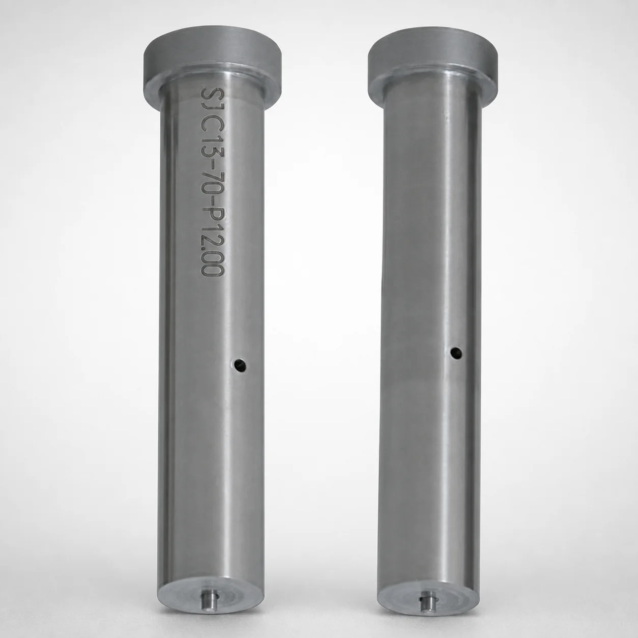
JIS Standard Steel Straight Ejector Punches - Lapping Option
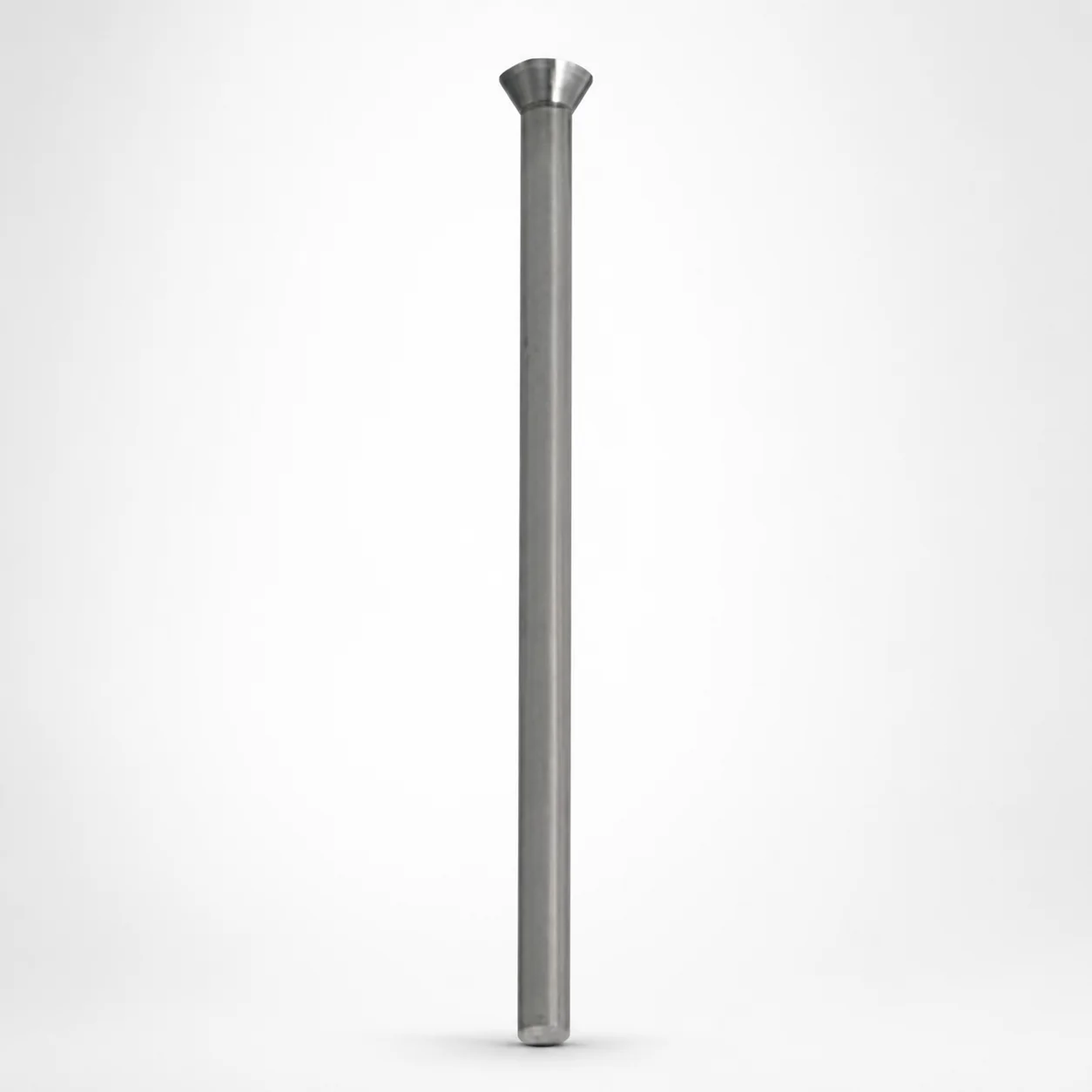
Straight ejector punches (Lapping Option) (SKD11/M2 equivalent steels) support accurate press-fit performance with a controlled surface finish for consistent tool alignment. The straight shank design helps deliver stable guidance in punching operations.
- Straight shank construction with standard type punch form for reliable handling
- Choice of SKD11 equivalent (D2) or SKH51 equivalent (M2) steels for wear resistance
- Optional lapping surface treatment helps achieve smoother contact and stable seating
- Used in die sets for repeatable ejection and positioning in manufacturing production lines
Specifications
64 configurations available
| Material | Surface Treatment | No. (Nominal diameter) (mm) | P (Tip dimension) (mm) | L (L dimension) (mm) | LC (Full length alteration) (mm) | LCT (Head thickness tolerance change + Total length alteration) (mm) | LMT (Head thickness tolerance change + Total length alteration) (mm) | type |
|---|---|---|---|---|---|---|---|---|
| SKH51 Equivalent (M2) | Lapping | 5 | 4.5 ~ 5 | 40 ~ 80 | - | - | - | - |
| SKH51 Equivalent (M2) | Lapping | 5 | 4.5 ~ 5 | - | 30 ~ 79.9 | - | - | - |
| SKH51 Equivalent (M2) | Lapping | 5 | 4.5 ~ 5 | - | - | 30 ~ 79.9 | - | - |
| SKH51 Equivalent (M2) | Lapping | 5 | 4.5 ~ 5 | - | - | - | 30 ~ 79.9 | - |
| SKH51 Equivalent (M2) | Lapping | 6 | 5 ~ 6 | 40 ~ 80 | - | - | - | - |
| SKH51 Equivalent (M2) | Lapping | 6 | 5 ~ 6 | - | 30 ~ 79.9 | - | - | - |
| SKH51 Equivalent (M2) | Lapping | 6 | 5 ~ 6 | - | - | 30 ~ 79.9 | - | - |
| SKH51 Equivalent (M2) | Lapping | 6 | 5 ~ 6 | - | - | - | 30 ~ 79.9 | - |
| SKD11 Equivalent (D2) | Lapping | 8 | 6 ~ 8 | 40 ~ 100 | - | - | - | - |
| SKD11 Equivalent (D2) | Lapping | 8 | 6 ~ 8 | - | 30 ~ 99.9 | - | - | - |
| SKD11 Equivalent (D2) | Lapping | 8 | 6 ~ 8 | - | - | 30 ~ 99.9 | - | - |
| SKD11 Equivalent (D2) | Lapping | 8 | 6 ~ 8 | - | - | - | 30 ~ 99.9 | - |
| SKD11 Equivalent (D2) | Lapping | 10 | 8 ~ 10 | 40 ~ 100 | - | - | - | - |
| SKD11 Equivalent (D2) | Lapping | 10 | 8 ~ 10 | - | 30 ~ 99.9 | - | - | - |
| SKD11 Equivalent (D2) | Lapping | 10 | 8 ~ 10 | - | - | 30 ~ 99.9 | - | - |
| SKD11 Equivalent (D2) | Lapping | 10 | 8 ~ 10 | - | - | - | 30 ~ 99.9 | - |
| SKD11 Equivalent (D2) | Lapping | 13 | 10 ~ 13 | 40 ~ 100 | - | - | - | - |
| SKD11 Equivalent (D2) | Lapping | 13 | 10 ~ 13 | - | 30 ~ 99.9 | - | - | - |
| SKD11 Equivalent (D2) | Lapping | 13 | 10 ~ 13 | - | - | 30 ~ 99.9 | - | - |
| SKD11 Equivalent (D2) | Lapping | 13 | 10 ~ 13 | - | - | - | 30 ~ 99.9 | - |
| SKD11 Equivalent (D2) | Lapping | 16 | 13 ~ 16 | 40 ~ 100 | - | - | - | - |
| SKD11 Equivalent (D2) | Lapping | 16 | 13 ~ 16 | - | 30 ~ 99.9 | - | - | - |
| SKD11 Equivalent (D2) | Lapping | 16 | 13 ~ 16 | - | - | 30 ~ 99.9 | - | - |
| SKD11 Equivalent (D2) | Lapping | 16 | 13 ~ 16 | - | - | - | 30 ~ 99.9 | - |
| SKD11 Equivalent (D2) | Lapping | 20 | 16 ~ 20 | 40 ~ 100 | - | - | - | - |
| SKD11 Equivalent (D2) | Lapping | 20 | 16 ~ 20 | - | 30 ~ 99.9 | - | - | - |
| SKD11 Equivalent (D2) | Lapping | 20 | 16 ~ 20 | - | - | 30 ~ 99.9 | - | - |
| SKD11 Equivalent (D2) | Lapping | 20 | 16 ~ 20 | - | - | - | 30 ~ 99.9 | - |
| SKD11 Equivalent (D2) | Lapping | 25 | 20 ~ 25 | 40 ~ 100 | - | - | - | - |
| SKD11 Equivalent (D2) | Lapping | 25 | 20 ~ 25 | - | 30 ~ 99.9 | - | - | - |
| SKD11 Equivalent (D2) | Lapping | 25 | 20 ~ 25 | - | - | 30 ~ 99.9 | - | - |
| SKD11 Equivalent (D2) | Lapping | 25 | 20 ~ 25 | - | - | - | 30 ~ 99.9 | - |
| SKH51 Equivalent (M2) | None | 5 | 4.5 ~ 5 | 40 ~ 80 | - | - | - | - |
| SKH51 Equivalent (M2) | None | 5 | 4.5 ~ 5 | - | 30 ~ 79.9 | - | - | - |
| SKH51 Equivalent (M2) | None | 5 | 4.5 ~ 5 | - | - | 30 ~ 79.9 | - | - |
| SKH51 Equivalent (M2) | None | 5 | 4.5 ~ 5 | - | - | - | 30 ~ 79.9 | - |
| SKH51 Equivalent (M2) | None | 6 | 5 ~ 6 | 40 ~ 80 | - | - | - | - |
| SKH51 Equivalent (M2) | None | 6 | 5 ~ 6 | - | 30 ~ 79.9 | - | - | - |
| SKH51 Equivalent (M2) | None | 6 | 5 ~ 6 | - | - | 30 ~ 79.9 | - | - |
| SKH51 Equivalent (M2) | None | 6 | 5 ~ 6 | - | - | - | 30 ~ 79.9 | - |
| SKD11 Equivalent (D2) | None | 8 | 6 ~ 8 | 40 ~ 100 | - | - | - | - |
| SKD11 Equivalent (D2) | None | 8 | 6 ~ 8 | - | 30 ~ 99.9 | - | - | - |
| SKD11 Equivalent (D2) | None | 8 | 6 ~ 8 | - | - | 30 ~ 99.9 | - | - |
| SKD11 Equivalent (D2) | None | 8 | 6 ~ 8 | - | - | - | 30 ~ 100 | - |
| SKD11 Equivalent (D2) | None | 10 | 8 ~ 10 | 40 ~ 100 | - | - | - | - |
| SKD11 Equivalent (D2) | None | 10 | 8 ~ 10 | - | 30 ~ 99.9 | - | - | - |
| SKD11 Equivalent (D2) | None | 10 | 8 ~ 10 | - | - | 30 ~ 99.9 | - | - |
| SKD11 Equivalent (D2) | None | 10 | 8 ~ 10 | - | - | - | 30 ~ 99.9 | - |
| SKD11 Equivalent (D2) | None | 13 | 10 ~ 13 | 40 ~ 100 | - | - | - | - |
| SKD11 Equivalent (D2) | None | 13 | 10 ~ 13 | - | 30 ~ 99.9 | - | - | - |
Product Guide
Application Scenarios+
These straight ejector punches with a lapping option are used in injection mold die sets where stable ejection force and precise tool alignment matter. In automotive connector and sensor molds, the smooth lapped contact surface helps maintain consistent press-fit seating in the punch plate, supporting reliable part release over high-cycle production.
For consumer electronics housings and camera/phone sub-assemblies, the straight shank geometry provides stable guidance during punching/ejection, reducing the risk of tilt that can accelerate wear on the ejector system.
In medical device packaging or precision insert molding tools, the controlled surface finish supports repeatable positioning and improves mating behavior within the ejector plate. The availability of wear-optimized steel variants (SKD11/D2 or SKH51/M2 equivalent) and the optional lapping surface make this variant well-suited for molds that demand dimensional stability and consistent contact.
- Automotive connector molds: improved seating consistency via lapping for stable ejection alignment
- Electronics housings: straight guidance to minimize tilt and wear during ejection
- Medical tooling: smoother contact behavior for repeatable punch positioning
Material & Process Details+
This series is available in SKD11 equivalent (D2) or SKH51 equivalent (M2) steels. SKD11/D2 is a high-carbon tool steel selected for strong wear resistance in relatively demanding punching and ejection applications, typically balancing toughness and hardness for long service life.
SKH51/M2 is a high-speed steel variant (HSS family) that provides excellent wear resistance and good ability to hold performance under heat generated by frequent cycling. Compared with SKD11/D2, M2/HSS generally offers improved hot hardness characteristics, but may involve a different toughness vs. wear trade-off depending on heat treatment and operating conditions.
- Surface treatment: lapping option improves contact smoothness; “None” preserves the base finish
- Heat treatment state: parts are supplied as hardened tool-steel components selected to achieve the target hardness for punching/ejector service (exact HRC depends on the selected grade and supplier processing)
- Hardness & wear: both variants prioritize wear resistance; lapped surfaces reduce frictional variability and help maintain seating stability
Sizing & Selection Guide+
To select the correct straight ejector punch, match the nominal diameter Ø5 ~ 25 mm to the ejector plate bore or guide/punch retaining feature diameter. Then confirm the tip dimension P in the range 4.5 ~ 20 mm to ensure the required working geometry reaches the cavity/core interface without interference.
For length selection, use the provided options for L (40 ~ 80 mm or 40 ~ 100 mm) and choose the appropriate full length alteration LC range (30 ~ 79.9, 30 ~ 99.9, or 20 ~ 99.9) based on your planned grind/adjustment allowance.
Check head thickness tolerance and total length alteration limits: LCT or LMT ranges define the allowable tolerance variation during adjustment. If you are using the lapping surface treatment, consider its effect on seating/contact behavior in the press-fit interface; dimensioning still follows the same Ø/P/L/LC limits, but fit smoothness may improve. Configurations are driven by diameter and length variants—material and surface treatment are selectable as SKD11/D2 or SKH51/M2 with optional lapping.
- Match Ø to the plate bore: Ø5–25 mm
- Match P to working tip requirement: 4.5–20 mm
- Select L from supported length sets: 40–80 or 40–100 mm
- Validate adjustment allowance using LC/LCT/LMT ranges
Frequently Asked Questions
Which steel should I choose for an ejector punch: SKD11 equivalent (D2) or SKH51 equivalent (M2) when cycles are high?+
Use SKD11 equivalent (D2) when your priority is strong wear resistance with a toughness balance suitable for typical ejector/punching duty. Choose SKH51 equivalent (M2) when higher wear resistance under the heat and friction generated by frequent cycling is critical. Your final selection should consider the specific mold duty cycle and whether your process generates significant temperature at the ejector plate interface.
What does the lapping option change, and where is it most beneficial in tool assembly?+
The lapping surface treatment improves the smoothness of the contact area compared with None. This is most beneficial at the press-fit seating interface in the ejector plate or punch guide, where smoother contact can improve repeatable alignment. For high-cycle molds, it can help reduce variability in seating behavior that contributes to misalignment over time.
How do I select the correct punch length (L) and adjustment allowance (LC/LCT/LMT) for the ejector system?+
Select L from the supported ranges of 40–80 mm or 40–100 mm, based on cavity stack height and how much protrusion you need. Then validate grinding/adjustment using the provided LC ranges (30–79.9, 30–99.9, or 20–99.9) and the tolerance change limits given by LCT and LMT (each supports multiple ranges). Ensure your planned adjustment stays within these limits to avoid exceeding allowable tolerance/alteration.
What diameter and tip dimensions should I verify against the ejector plate bore and cavity/core clearance?+
Confirm nominal diameter Ø within 5–25 mm to match the ejector plate bore/retention feature. Verify P (tip dimension) in the 4.5–20 mm range so the punch tip performs the intended ejection or punching action without interference. Also check that the chosen L provides the necessary reach for the cavity/core interface.
Is this straight ejector punch available in fixed dimensions or multiple variants per diameter/length?+
It is offered in multiple dimensional variants driven by the nominal diameter range (5–25 mm) and the supported length/tolerance alteration ranges for L, LC, LCT, and LMT. Material is also configurable between SKD11 equivalent (D2) and SKH51 equivalent (M2), and the surface treatment can be lapping or None. This makes it adaptable to different die set stack-ups and adjustment strategies.
Related Products
Need Custom Specifications?
Our engineering team can help with custom configurations, material selection, and volume pricing.