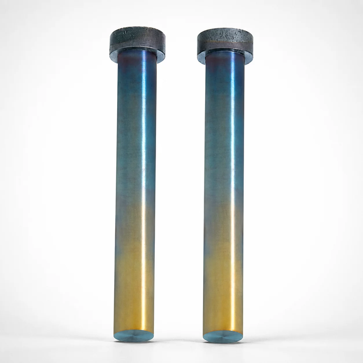
Straight Punches - DLC (XCD) Coating
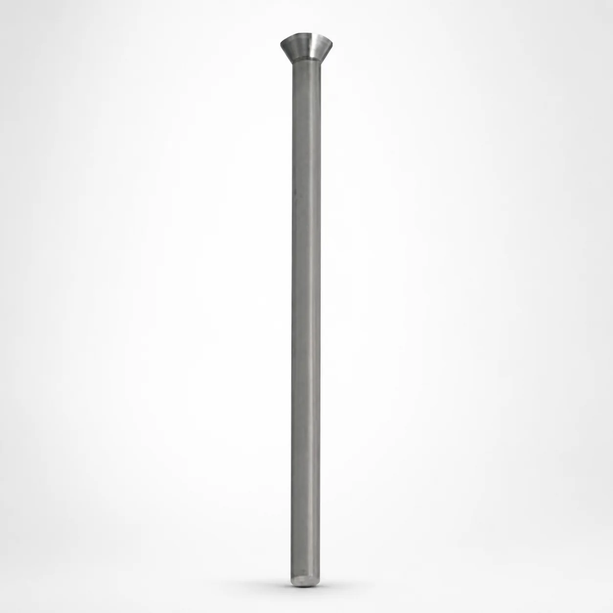
Straight Punches - DLC (XCD) Coating are designed for stable, straight press-fit forming in die and mold assemblies. The DLC (XCD) coating improves surface durability under repeated contact and sliding.
- Straight shank punch with standard mounting geometry for reliable guidance
- DLC (XCD) coating enhances wear resistance and reduces friction during operation
- Machined punches support consistent assembly with controlled head thickness T = 5 mm
- Suitable for punch applications requiring long-lasting performance in industrial tooling
Specifications
72 configurations available
| Material | No. (Nominal diameter) (mm) | P (Tip dimension) (mm) | L (L dimension) (mm) | LC (Full length alteration) (mm) | LCT (Head thickness tolerance change + Total length alteration) (mm) | LMT (Head thickness tolerance change + Total length alteration) (mm) | type |
|---|---|---|---|---|---|---|---|
| SKH40 Equivalent (Powdered high-speed steel) | 4 | 3 ~ 4 | 40 ~ 80 | - | - | - | - |
| SKH40 Equivalent (Powdered high-speed steel) | 4 | 3 ~ 4 | - | 20 ~ 80 | - | - | - |
| SKH40 Equivalent (Powdered high-speed steel) | 4 | 3 ~ 4 | - | - | 20 ~ 80 | - | - |
| SKH40 Equivalent (Powdered high-speed steel) | 4 | 3 ~ 4 | - | - | - | 20 ~ 80 | - |
| SKH40 Equivalent (Powdered high-speed steel) | 5 | 4 ~ 5 | 40 ~ 80 | - | - | - | - |
| SKH40 Equivalent (Powdered high-speed steel) | 5 | 4 ~ 5 | - | 20 ~ 80 | - | - | - |
| SKH40 Equivalent (Powdered high-speed steel) | 5 | 4 ~ 5 | - | - | 20 ~ 80 | - | - |
| SKH40 Equivalent (Powdered high-speed steel) | 5 | 4 ~ 5 | - | - | - | 20 ~ 80 | - |
| SKH40 Equivalent (Powdered high-speed steel) | 6 | 5 ~ 6 | 40 ~ 80 | - | - | - | - |
| SKH40 Equivalent (Powdered high-speed steel) | 6 | 5 ~ 6 | - | 20 ~ 80 | - | - | - |
| SKH40 Equivalent (Powdered high-speed steel) | 6 | 5 ~ 6 | - | - | 20 ~ 80 | - | - |
| SKH40 Equivalent (Powdered high-speed steel) | 6 | 5 ~ 6 | - | - | - | 20 ~ 80 | - |
| SKH40 Equivalent (Powdered high-speed steel) | 8 | 6 ~ 8 | 40 ~ 100 | - | - | - | - |
| SKH40 Equivalent (Powdered high-speed steel) | 8 | 6 ~ 8 | - | 20 ~ 100 | - | - | - |
| SKH40 Equivalent (Powdered high-speed steel) | 8 | 6 ~ 8 | - | - | 20 ~ 100 | - | - |
| SKH40 Equivalent (Powdered high-speed steel) | 8 | 6 ~ 8 | - | - | - | 20 ~ 100 | - |
| SKH40 Equivalent (Powdered high-speed steel) | 10 | 8 ~ 10 | 40 ~ 100 | - | - | - | - |
| SKH40 Equivalent (Powdered high-speed steel) | 10 | 8 ~ 10 | - | 20 ~ 100 | - | - | - |
| SKH40 Equivalent (Powdered high-speed steel) | 10 | 8 ~ 10 | - | - | 20 ~ 100 | - | - |
| SKH40 Equivalent (Powdered high-speed steel) | 10 | 8 ~ 10 | - | - | - | 20 ~ 100 | - |
| SKH40 Equivalent (Powdered high-speed steel) | 13 | 10 ~ 13 | 40 ~ 120 | - | - | - | - |
| SKH40 Equivalent (Powdered high-speed steel) | 13 | 10 ~ 13 | - | 20 ~ 120 | - | - | - |
| SKH40 Equivalent (Powdered high-speed steel) | 13 | 10 ~ 13 | - | - | 20 ~ 120 | - | - |
| SKH40 Equivalent (Powdered high-speed steel) | 13 | 10 ~ 13 | - | - | - | 20 ~ 120 | - |
| SKH40 Equivalent (Powdered high-speed steel) | 16 | 13 ~ 16 | 40 ~ 120 | - | - | - | - |
| SKH40 Equivalent (Powdered high-speed steel) | 16 | 13 ~ 16 | - | 20 ~ 120 | - | - | - |
| SKH40 Equivalent (Powdered high-speed steel) | 16 | 13 ~ 16 | - | - | 20 ~ 120 | - | - |
| SKH40 Equivalent (Powdered high-speed steel) | 16 | 13 ~ 16 | - | - | - | 20 ~ 120 | - |
| SKH40 Equivalent (Powdered high-speed steel) | 20 | 16 ~ 20 | 40 ~ 120 | - | - | - | - |
| SKH40 Equivalent (Powdered high-speed steel) | 20 | 16 ~ 20 | - | 20 ~ 120 | - | - | - |
| SKH40 Equivalent (Powdered high-speed steel) | 20 | 16 ~ 20 | - | - | 20 ~ 120 | - | - |
| SKH40 Equivalent (Powdered high-speed steel) | 20 | 16 ~ 20 | - | - | - | 20 ~ 120 | - |
| SKH40 Equivalent (Powdered high-speed steel) | 25 | 20 ~ 25 | 40 ~ 120 | - | - | - | - |
| SKH40 Equivalent (Powdered high-speed steel) | 25 | 20 ~ 25 | - | 20 ~ 120 | - | - | - |
| SKH40 Equivalent (Powdered high-speed steel) | 25 | 20 ~ 25 | - | - | 20 ~ 120 | - | - |
| SKH40 Equivalent (Powdered high-speed steel) | 25 | 20 ~ 25 | - | - | - | 20 ~ 120 | - |
| SKH51 Equivalent (M2) | 4 | 3 ~ 4 | 40 ~ 80 | - | - | - | - |
| SKH51 Equivalent (M2) | 4 | 3 ~ 4 | - | 20 ~ 80 | - | - | - |
| SKH51 Equivalent (M2) | 4 | 3 ~ 4 | - | - | 20 ~ 80 | - | - |
| SKH51 Equivalent (M2) | 4 | 3 ~ 4 | - | - | - | 20 ~ 80 | - |
| SKH51 Equivalent (M2) | 5 | 4 ~ 5 | 40 ~ 80 | - | - | - | - |
| SKH51 Equivalent (M2) | 5 | 4 ~ 5 | - | 20 ~ 80 | - | - | - |
| SKH51 Equivalent (M2) | 5 | 4 ~ 5 | - | - | 20 ~ 80 | - | - |
| SKH51 Equivalent (M2) | 5 | 4 ~ 5 | - | - | - | 20 ~ 80 | - |
| SKH51 Equivalent (M2) | 6 | 5 ~ 6 | 40 ~ 80 | - | - | - | - |
| SKH51 Equivalent (M2) | 6 | 5 ~ 6 | - | 20 ~ 80 | - | - | - |
| SKH51 Equivalent (M2) | 6 | 5 ~ 6 | - | - | 20 ~ 80 | - | - |
| SKH51 Equivalent (M2) | 6 | 5 ~ 6 | - | - | - | 20 ~ 80 | - |
| SKH51 Equivalent (M2) | 8 | 6 ~ 8 | 40 ~ 100 | - | - | - | - |
| SKH51 Equivalent (M2) | 8 | 6 ~ 8 | - | 20 ~ 100 | - | - | - |
Product Guide
Application Scenarios+
These straight punches with a DLC (XCD) surface are used in die and mold tool blocks where press-fit forming, guidance, and repeated contact demand stable performance. The straight geometry supports consistent alignment in both cold-working and feeder/transfer stations, helping maintain uniform piercing or forming force distribution over cycles.
- Automotive and industrial connector tooling: apply for long-run punch stations where sliding contact occurs between punch tip and forming die faces; the DLC (XCD) coating reduces friction and improves surface durability.
- Electronics enclosure and bracket molds: suitable for straight press-fit operations requiring controlled guidance; machined shanks improve repeatable assembly while the coating supports wear resistance under frequent part ejection/actuation.
- General die & progressive forming applications: compatible with SKH40/SKH51-equivalent steel bases for applications needing high-speed steel toughness with enhanced wear behavior at the contact surfaces.
With a controlled head thickness T = 5 mm, this variant is suited for tooling layouts that require consistent head-to-total-length relationships for assembly and long-term dimensional stability.
Material & Process Details+
Base materials are offered in SKH40 equivalent (powdered high-speed steel) and SKH51 equivalent (M2). SKH40 is typically selected when a balance of wear resistance and toughness is required for stable guidance in repetitive punching, while SKH51/M2 is commonly chosen for higher wear capability in die and punch work.
For DLC (XCD) coated punches, the wear and friction performance is driven by the surface film on top of the hardened HSS substrate. While specific hardness values are not provided in the data, engineers should verify final hardness after tool heat treatment and before coating application to ensure the intended HRC level matches die-block requirements.
- Heat treatment (typical): quenched & tempered HSS substrate followed by DLC (XCD) coating for reduced sliding wear.
- Trade-off: increasing wear resistance via higher-hardness HSS states can slightly reduce toughness—select SKH40 vs SKH51 based on expected load, impact risk, and sliding distance.
Sizing & Selection Guide+
To select the correct straight punch dimensions, match the nominal diameter and the tip dimension (P) to the die opening geometry and the press-fit/forming requirement. The nominal diameter range is 4–25 mm and tip dimension range is 3–20 mm.
- Choose working length: select L from the provided options (40–80, 40–100, or 40–120 mm) based on how much projection is required in the tool stack-up.
- Confirm full-length alteration (LC): pick the matching alteration range (20–80, 20–100, or 20–120 mm) for the intended adjustment/clearance strategy.
- Validate head thickness relationship: the head thickness is controlled at T = 5 mm, and the head thickness tolerance change with total length alteration is represented by LCT and LMT ranges (each offered as 20–80, 20–100, 20–120).
Where press-fit guidance is critical, confirm tolerance compatibility between punch and the mating die bore; the coated surface affects wear behavior but not the underlying dimensional interface, so verify your assembly fit using the selected diameter and length configuration.
Frequently Asked Questions
Which steel base should I select for this straight punch: SKH40 equivalent (powdered HSS) or SKH51 equivalent (M2)?+
Use SKH40 equivalent (powdered HSS) when you need a balanced wear/toughness profile for repeated die and punch guidance. Choose SKH51 equivalent (M2) when higher wear resistance is prioritized for punch tip and sliding contact durability. Both variants are designed for die and mold work with improved surface behavior provided by the DLC (XCD) coating.
How do the provided L, LC, LCT, and LMT ranges affect total length and head-to-length consistency?+
The data provides configurable length families for L (40–80, 40–100, 40–120 mm) along with corresponding alteration and tolerance-change ranges: LC (20–80, 20–100, 20–120), LCT (20–80, 20–100, 20–120), and LMT (20–80, 20–100, 20–120). For tool design, you should select the same family across L/LC and then verify the intended head-to-total-length relationship using the stated tolerance-change parameters. The punch head thickness is controlled at T = 5 mm.
What are the allowable nominal diameter and tip dimension ranges for sizing the press-fit interface?+
The nominal diameter range is 4–25 mm and the tip dimension P range is 3–20 mm. Match these values to your die opening and press-fit/forming geometry to achieve the intended guidance and load transfer. Because the punch is straight and designed for stable forming, incorrect diameter selection can cause binding or uneven contact.
Does the DLC (XCD) coating replace the need to select the right steel grade and heat treatment state?+
No. The DLC (XCD) coating improves wear resistance and reduces friction during repeated sliding contact, but the underlying performance still depends on the SKH40 equivalent or SKH51/M2 equivalent substrate and its final hardness after heat treatment. Since hardness in HRC is not specified in the provided data, you should confirm your intended hardness state to ensure coating adhesion and durability under your expected load and cycle count.
How can I ensure correct protrusion length when integrating this punch into a tool stack-up?+
Select L from the offered options (40–80, 40–100, 40–120 mm) to match the required protrusion. If your design uses controlled adjustments, select the corresponding LC family (20–80, 20–100, 20–120) and verify the related tolerance-change parameters LCT and LMT. Keep T = 5 mm in mind when calculating the head-to-projection clearance in your assembled cavity/core.
Related Products
Need Custom Specifications?
Our engineering team can help with custom configurations, material selection, and volume pricing.