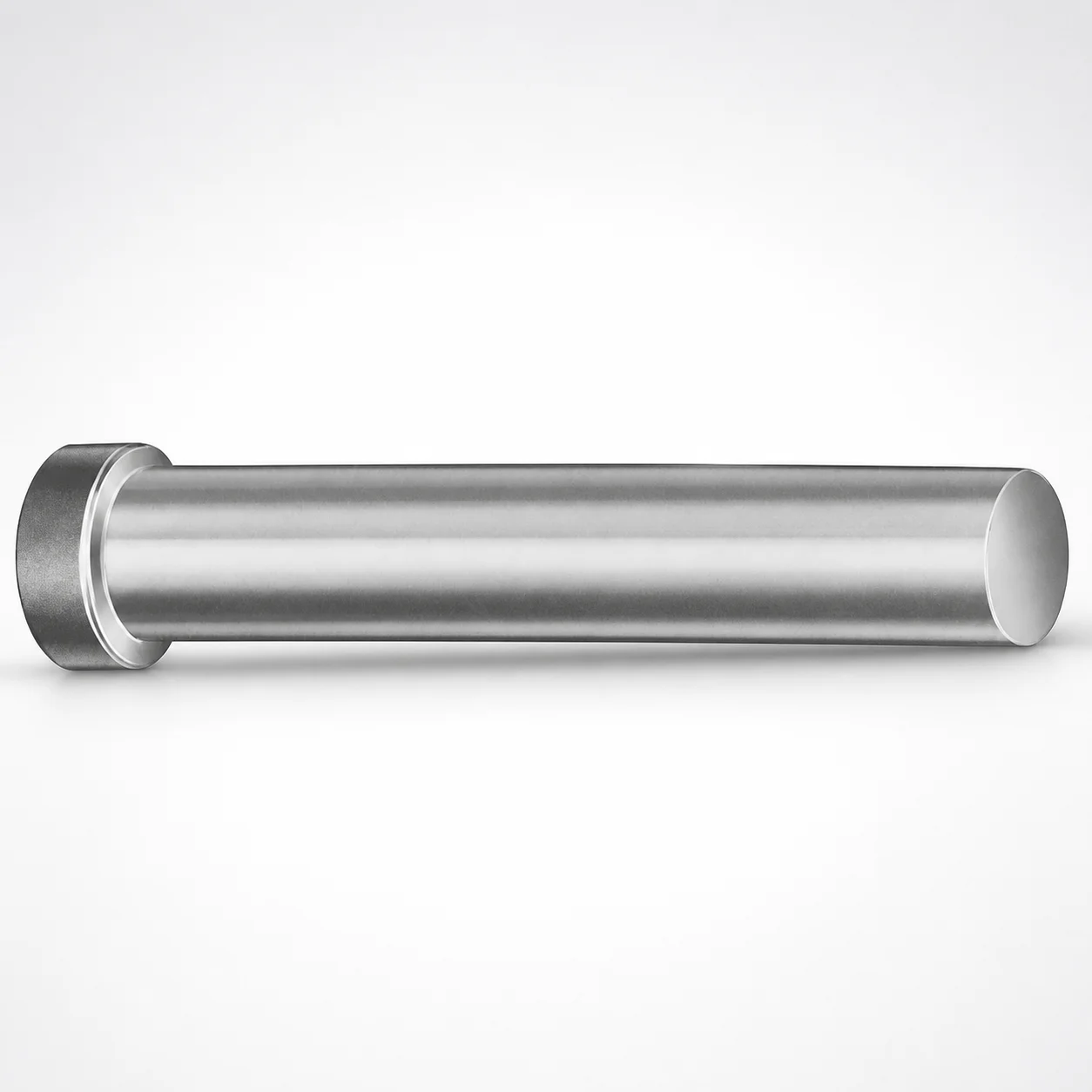
Inch Standard Straight Regular Punches XNA Coating
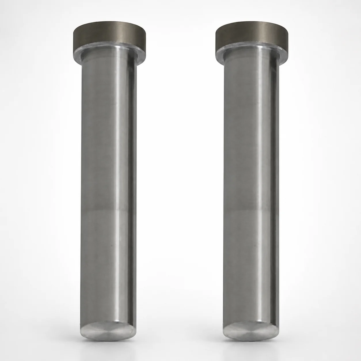
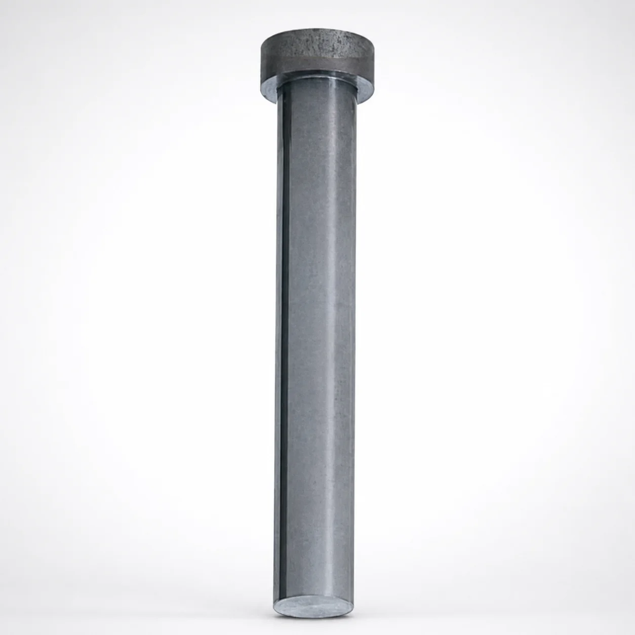
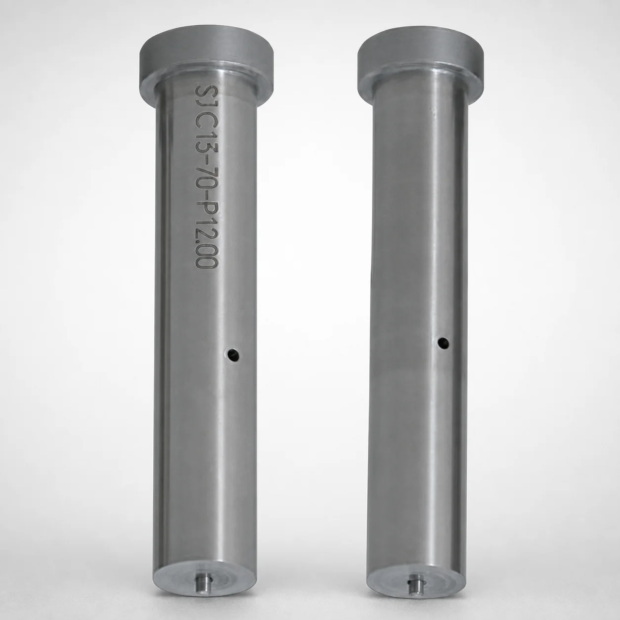
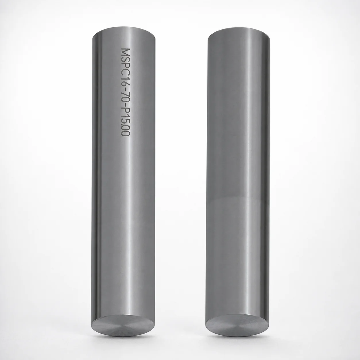
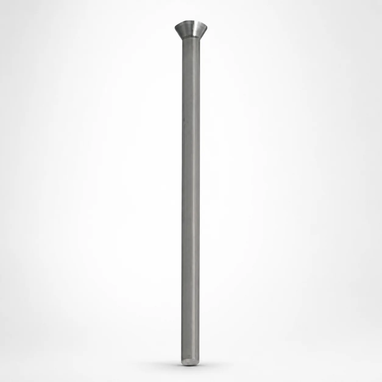
Straight Regular Punches for inch tooling (XNA coating) are designed to support consistent forming cycles with reliable surface durability in production molds and dies. They help maintain punch stability for repeatable part ejection.
- Inch straight punch geometry for stable alignment during punching
- Uses XNA coating to improve wear resistance under repeated cycles
- Supports configurable L length and P dimension ranges for tool fitting
- Commonly used in stamping and die applications requiring straight punch performance
Specifications
1 configurations available
| L (Length) (in) | P Dimension (in) |
|---|---|
| 150 ~ 625 | 0.125 ~ 0.375 |
Product Guide
Application Scenarios+
These inch-standard straight regular punches are used in progressive and transfer die sets where consistent ejection force and repeatable punching cycles are critical. The straight punch geometry supports stable alignment, helping reduce wobble and uneven wear at the working end.
In automotive stamping operations, they are commonly sized to match specific die clearances and punch holders, and the XNA surface coating improves wear resistance under high cycle counts. This helps maintain dimensional stability of the punching land during long production runs.
They are also suitable for appliance and metal forming dies that require reliable straight-punch performance. Engineers typically select the L length (150–625 in) to fit the press height and tool stack-up, while the P dimension (0.125–0.375 in) is matched to the required working interface for secure engagement.
- Best fit for stamping/die tooling needing straight alignment and stable ejection
- XNA coating supports durable surface life under repeated contact
Material & Process Details+
The product data specifies an XNA coating for enhanced wear resistance, intended to reduce surface degradation under repeated punching contact. While a base steel grade and heat treatment state are not provided in the available specifications, the coating’s role is to improve friction and wear performance at the working face.
For mold engineers comparing options, the key differentiation is typically coated versus uncoated tool surfaces: coated punches prioritize longer wear life and more consistent surface condition across production cycles. In high-load stamping, this often means lower maintenance frequency and more stable punch geometry over time.
- XNA coating: targeted for durable wear resistance under repeated cycles
- Heat treatment, hardness (HRC), and steel grade: not specified in provided data
- Trade-off focus: wear life and surface durability (vs. underlying toughness controlled by base steel)
Sizing & Selection Guide+
To select the correct punch size, start with your die layout and tool stack requirements. The L (Length) range is 150–625 in, which should be chosen to provide proper protrusion through the die and safe engagement in the punch holder without bottoming or excessive stick-out.
Next, match the P dimension range of 0.125–0.375 in to the required working interface in your punching station. This dimension is typically used to ensure correct fit and stable support at the punch/die contact region.
- L (in): confirm press height and stacking tolerances so the punch length supports repeatable ejection
- P (in): verify clearance and engagement requirements to prevent uneven wear or chipping
- Fixed dimensions: L and P are provided as fixed available ranges (no alternate configurable geometry indicated)
If you have tight clearance targets, account for holder alignment and assembly fit, since even small deviations can affect wear pattern and punch stability during cycling.
Frequently Asked Questions
What are the available fixed dimension ranges for this inch straight regular punch?+
This punch series specifies L (Length) = 150–625 in and P dimension = 0.125–0.375 in. These are the fixed available ranges provided for tool fitting and station design.
How does the XNA coating improve punch performance in stamping or die applications?+
The XNA coating is intended to improve wear resistance under repeated punching contact. In production tooling, this helps maintain surface durability and more consistent punch behavior across long cycle runs.
When should I choose a straight punch geometry for my die design?+
Choose the straight regular punch geometry when your tooling requires stable alignment to reduce wobble and uneven wear at the working end. It is especially relevant for stamping and die stations where repeatable ejection and punch stability are needed.
How do I match L length to my punch holder and press height stack-up?+
Select L within 150–625 in so the punch provides the required protrusion through the die while maintaining safe engagement in the holder. Verify the tool stack-up (die thickness, plates, and clearance) so the punch does not bottom out or extend excessively.
What is the correct way to use the P dimension during die clearance and fit checks?+
Use the P dimension (0.125–0.375 in) to match the designed working interface in your punching station. Confirm clearance and engagement so the punch is supported consistently, which helps prevent stress concentration and uneven wear.
Related Products
Need Custom Specifications?
Our engineering team can help with custom configurations, material selection, and volume pricing.