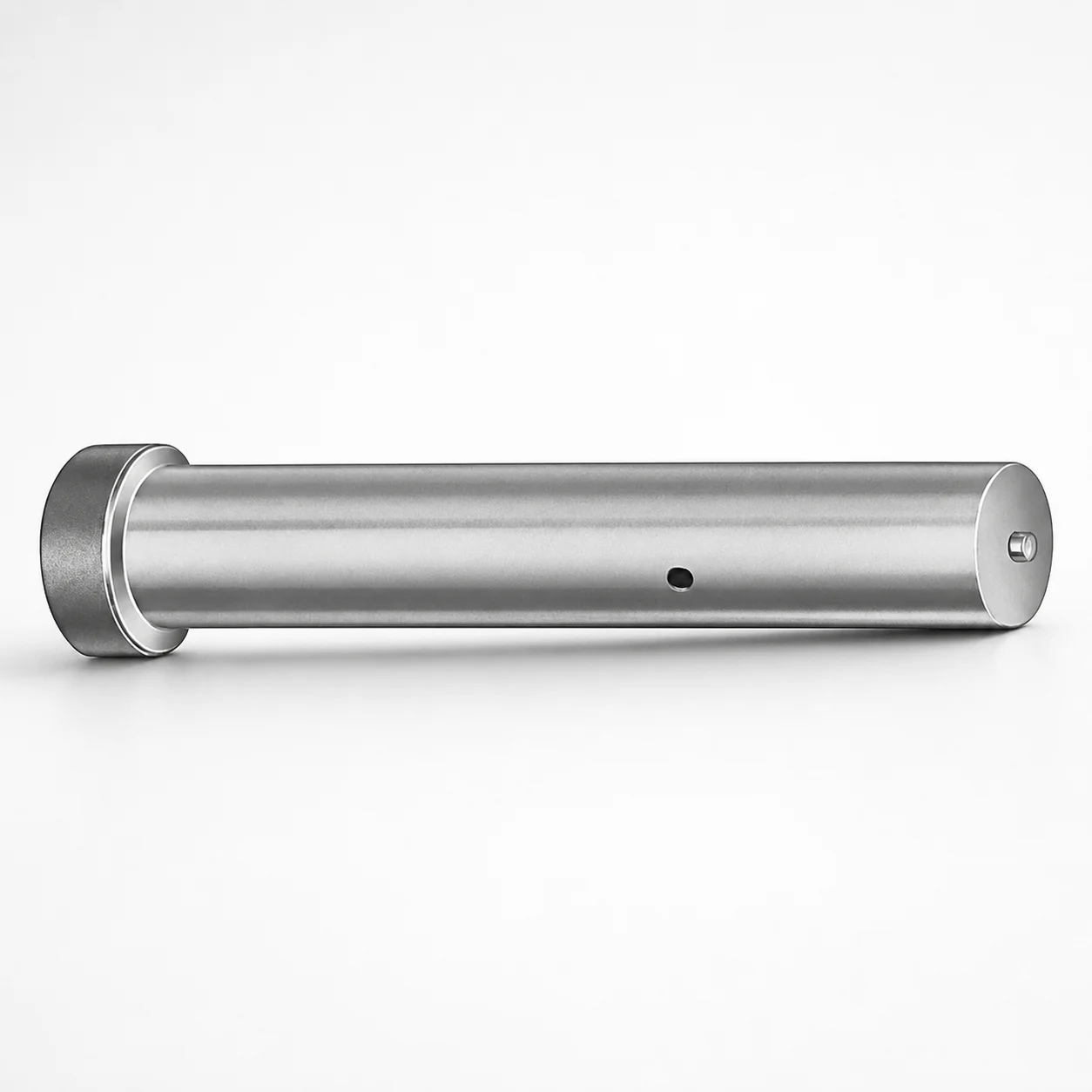
Metric Straight Ejector Punches with XNA Coating
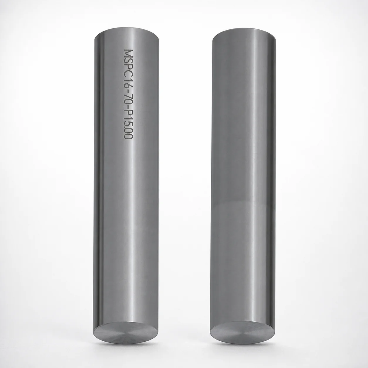
Metric straight ejector punches with XNA coating provide reliable workpiece release in die and mold ejector mechanisms. The standardized punch design helps maintain consistent positioning and stable operation across production runs.
- Direct straight punch geometry supports stable ejection performance
- XNA coating helps improve wear resistance for longer punch service
- Designed for metric assemblies with consistent fit in ejector layouts
- Suitable for standard die maintenance and repeated molding cycles
Specifications
1 configurations available
| L (Length) (mm) | P Dimension (mm) |
|---|---|
| 50 ~ 90 | 5 ~ 16 |
Product Guide
Application Scenarios+
Straight ejector punch tooling is commonly used to transfer mold force to the part and ensure consistent release from the cavity, especially in high-cycle injection and die casting workflows. This punch variant is well-suited where designers need predictable straight-contact motion and stable alignment within the ejector system.
In automotive and industrial component molds, straight ejection helps maintain uniform contact along the punch axis, reducing the risk of binding during repeated cycles. The XNA coating supports improved wear performance under the sliding action typical of ejector return and actuation.
In die casting and overmolding applications, ejector mechanisms experience abrasive contact from hot metal and solidified skins. The metric sizing and standardized geometry support integration into existing ejector layouts while maintaining smooth ejection across production runs.
- Use with metric ejector pads and housings that match punch axial alignment needs
- Recommended for systems prioritizing stable positioning and longer service life under sliding wear
Material & Process Details+
The provided specifications identify this as a metric straight ejector punch with XNA coating, but they do not include the underlying steel grade or hardness values. For accurate heat-treatment and metallurgy matching, request the steel grade and coating thickness data from the supplier documentation.
XNA coating is the key material differentiator described for this part. In ejector service, the coating primarily targets wear resistance and reduced friction during sliding contact, helping maintain ejection consistency over repeated cycles.
Heat treatment and hardness (HRC) should be verified for your specific application loads:
- Higher hardness generally improves abrasion and wear resistance but can reduce toughness if pushback/impact loads are high
- Quenched & tempered tool steels are typical for balanced toughness/wear, while nitriding is sometimes used for surface wear dominance (confirm for this SKU)
Material comparison cannot be performed from the supplied dataset because alternate steel grades are not provided.
Sizing & Selection Guide+
Selection of the correct punch size is governed by the two fixed dimensions supplied: L (Length) = 50–90 mm and P = 5–16 mm. L determines how much effective travel/contact length the ejector system provides, while P (the specified cross/fit dimension) controls compatibility with the ejector layout and surrounding components.
To size for your mold cavity/core, first match P to the corresponding ejector bore, bushing, or guide interface dimension in your assembly drawings. Then choose L to ensure sufficient engagement for reliable part push-off without excessive stick-out that could increase bending under load.
- Confirm whether P is the diameter/critical fit dimension for your guide system and maintain the designed clearance for smooth movement
- Check that the selected L supports the required stroke while leaving margin for safe return and maintenance access
- Because tolerance data is not provided, apply your standard mold-maker fit strategy (e.g., guide clearance limits) and verify with the supplier’s dimensional tolerance sheet
Dimensions are fixed-range configurable within L = 50–90 mm and P = 5–16 mm; choose the nearest required value to your CAD/Ejector BOM.
Frequently Asked Questions
What are the available length (L) and P dimension ranges for this metric straight ejector punch?+
The punch provides a fixed L (Length) range of 50–90 mm and a fixed P dimension range of 5–16 mm. Select the combination that matches your ejector layout engagement length (L) and the critical interface/fit dimension (P).
How does the XNA coating improve ejector performance in sliding mold systems?+
This SKU is specified with XNA coating, which is intended to improve wear resistance during repeated ejector actuation. In sliding contact, the coating helps maintain smoother motion and more consistent ejection over production cycles.
Which dimension should I use to verify compatibility with my ejector guide/bushing interface?+
Compatibility is primarily controlled by the specified P dimension range (5–16 mm). Verify that your ejector bore, bushing, or guide interface dimension is designed to accept the selected P value, and then confirm L provides the required engagement without overextension.
Can I rely on the provided data to select the steel grade and hardness for my mold load case?+
The supplied dataset does not include the underlying steel grade or hardness (HRC) for this punch. For load-critical designs, you should request the material/coating technical sheet for hardness, heat treatment state, and any tolerance details tied to this SKU.
What application types are most appropriate for straight ejector punches with XNA coating?+
This product description targets die casting and molding ejector systems where smooth ejection and wear resistance matter. The straight punch geometry supports stable axial ejection performance, and the XNA coating is positioned to help extend service life under sliding wear conditions.
Related Products
Need Custom Specifications?
Our engineering team can help with custom configurations, material selection, and volume pricing.