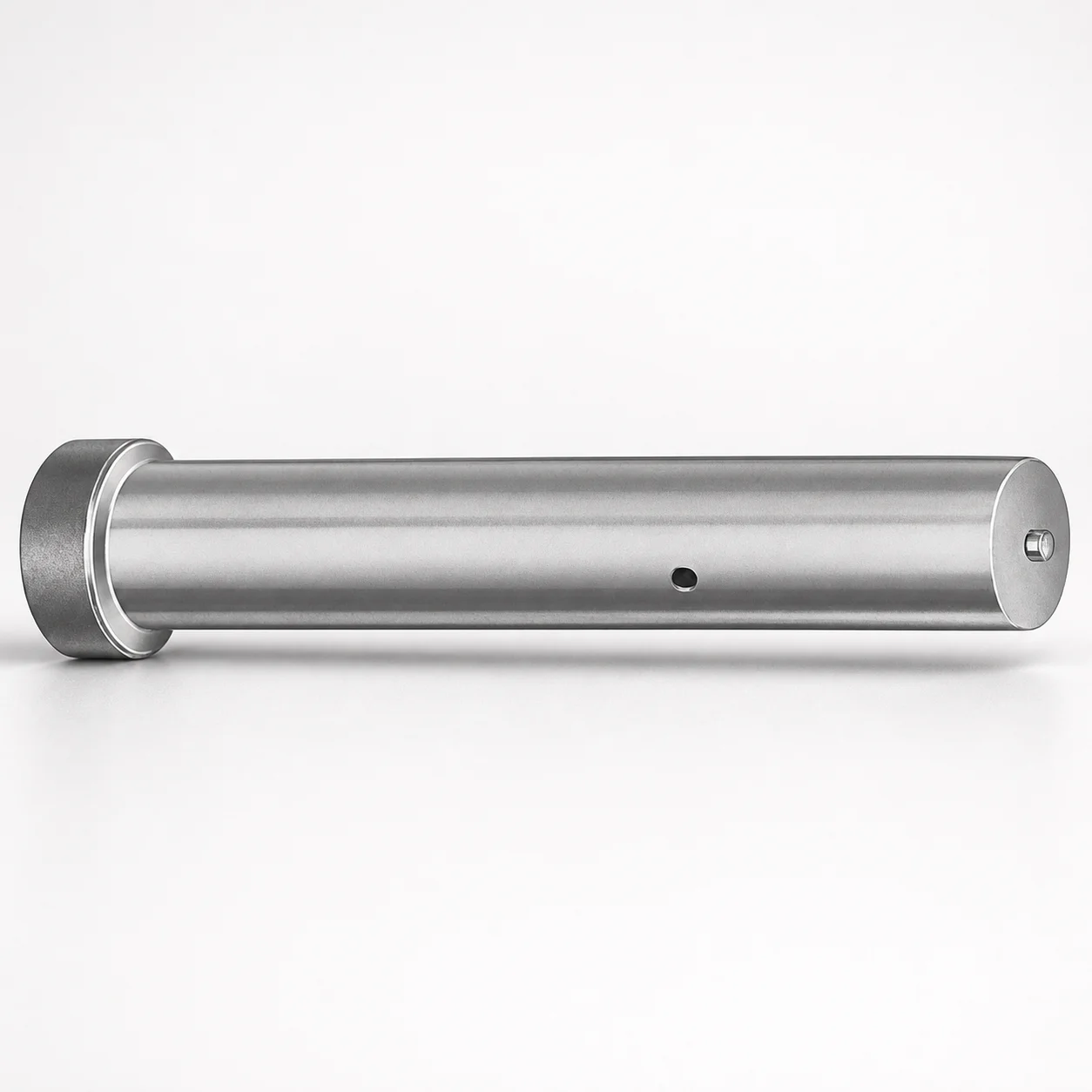
Metric Straight Ejector Punches XCDP Coating
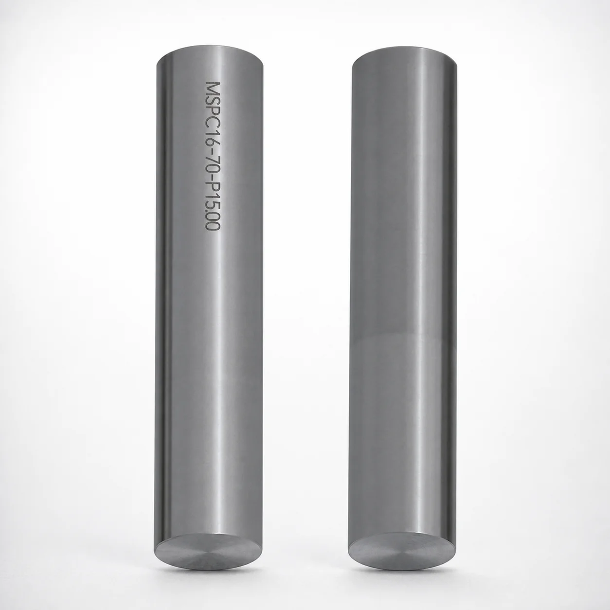
Metric straight ejector punches (XCDP coating) deliver reliable ejection performance with a wear-resistant surface designed for long production runs. Built for efficient punch alignment in die and mold assemblies.
- Straight ejector punch geometry supports consistent ejection in dies
- XCDP coating enhances durability for abrasive and high-cycle work
- DAYTON LAMINA standardized part numbering improves ordering accuracy
- Use in metric stamping tools, die sets, and precision mold systems
Specifications
1 configurations available
| L (Length) (mm) | P Dimension (mm) |
|---|---|
| 50 ~ 90 | 5 ~ 16 |
Product Guide
Application Scenarios+
Metric straight ejector punches with an XCDP-coated wear surface are used in injection tooling and related die systems where consistent part release and stable punch alignment are critical. They suit automotive and appliance housings where long-cycle production demands repeatable ejection with minimal surface degradation.
In precision insert and die-set applications, the straight geometry supports predictable ejection travel and helps maintain alignment between moving ejector plates and the mating mold features.
For high-abrasion molding conditions (fine glass-filled materials, gritty reinforcements, or abrasive molding residues), the XCDP coating is selected to improve wear resistance and reduce the rate of dimensional drift over time.
- Matched for metric tooling environments with L = 50–90 mm and P = 5–16 mm
- Designed for efficient installation against DAYTON LAMINA part standards to support correct replacement and tooling maintenance
Material & Process Details+
This specific ejector punch variant is defined by its XCDP coating, which is selected to enhance wear resistance at the sliding and contacting surface. While the provided data does not list a base steel grade or exact hardness value, the coating performance is intended to improve durability during high-cycle ejection.
In manufacturing, punches like these are typically produced from a punch body material that is machined to the required straight geometry, then receive a surface coating to improve resistance to abrasive wear. The key trade-off is that added surface hardness and tribological stability from the coating must be balanced with maintaining sufficient punch toughness to avoid brittle failure under intermittent impact during ejection.
- XCDP coating: targeted wear reduction for abrasive/high-cycle operation
- Trade-off: optimized surface durability while relying on the underlying punch body for toughness
Sizing & Selection Guide+
Select the correct metric straight ejector punch size by matching the required ejection length and the punch-related mounting/fit dimension to your ejector layout.
- Length (L): choose from 50–90 mm. Match L to the effective stroke requirement so the punch engages the part geometry reliably without bottoming in the return position.
- P dimension: choose from 5–16 mm. Use P to align with the tooling design that controls the punch diameter/section and supports proper guidance in the ejector plate or wear components.
When integrating into a cavity/core ejection system, verify that the punch length covers the full clearance envelope during opening and maintains contact pressure during ejection. Because tolerances are not provided in the specification data, confirm fit through your existing mold tolerance stack and guidance methods (e.g., ejector bushing/plate clearances) before final design lock.
These dimensions are fixed ranges (not configurable on a per-order basis beyond selecting a value within the listed intervals).
Frequently Asked Questions
Which dimensions control the ejector punch selection for this metric straight punch series?+
Selection is governed by L (length) = 50–90 mm and P = 5–16 mm. Use L to cover the required engagement and travel without bottoming, and use P to match the punch-related mounting/fit dimension in your ejector plate or guide interface.
Why is XCDP coating used on straight ejector punches in high-cycle molding?+
The XCDP coating is intended to improve wear resistance on the punch surface, supporting stable ejection over long production runs. This is especially useful where abrasive residues or reinforced polymers increase surface wear and can lead to dimensional drift.
How does straight ejector punch geometry affect alignment in die and mold assemblies?+
The straight geometry is selected to support predictable ejection and to maintain alignment between the ejector components and the contacting mold features. In die sets and precision systems, this reduces inconsistent contact that can otherwise cause uneven part release.
Is this punch aligned to DAYTON LAMINA part numbering standards for replacements?+
Yes. The part is described as being made to DAYTON LAMINA standardized part standards, which helps reduce ordering mistakes and supports correct replacement in tooling maintenance programs. Use the series code 250301354071 as the SKU reference when matching existing tooling.
What fit/tolerance should I verify when integrating the punch into my ejector system?+
The data provided lists L = 50–90 mm and P = 5–16 mm, but it does not specify tolerance values. You should confirm your clearance and guidance method (ejector bushing/plate fit) against your tolerance stack to ensure proper movement and prevent binding during ejection and return.
Related Products
Need Custom Specifications?
Our engineering team can help with custom configurations, material selection, and volume pricing.