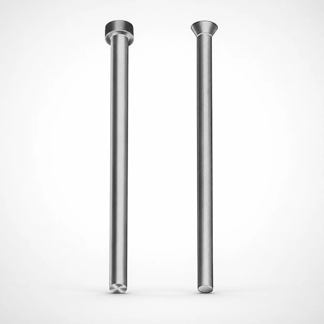
Close Space Straight Punches - Inch, XNP Coating
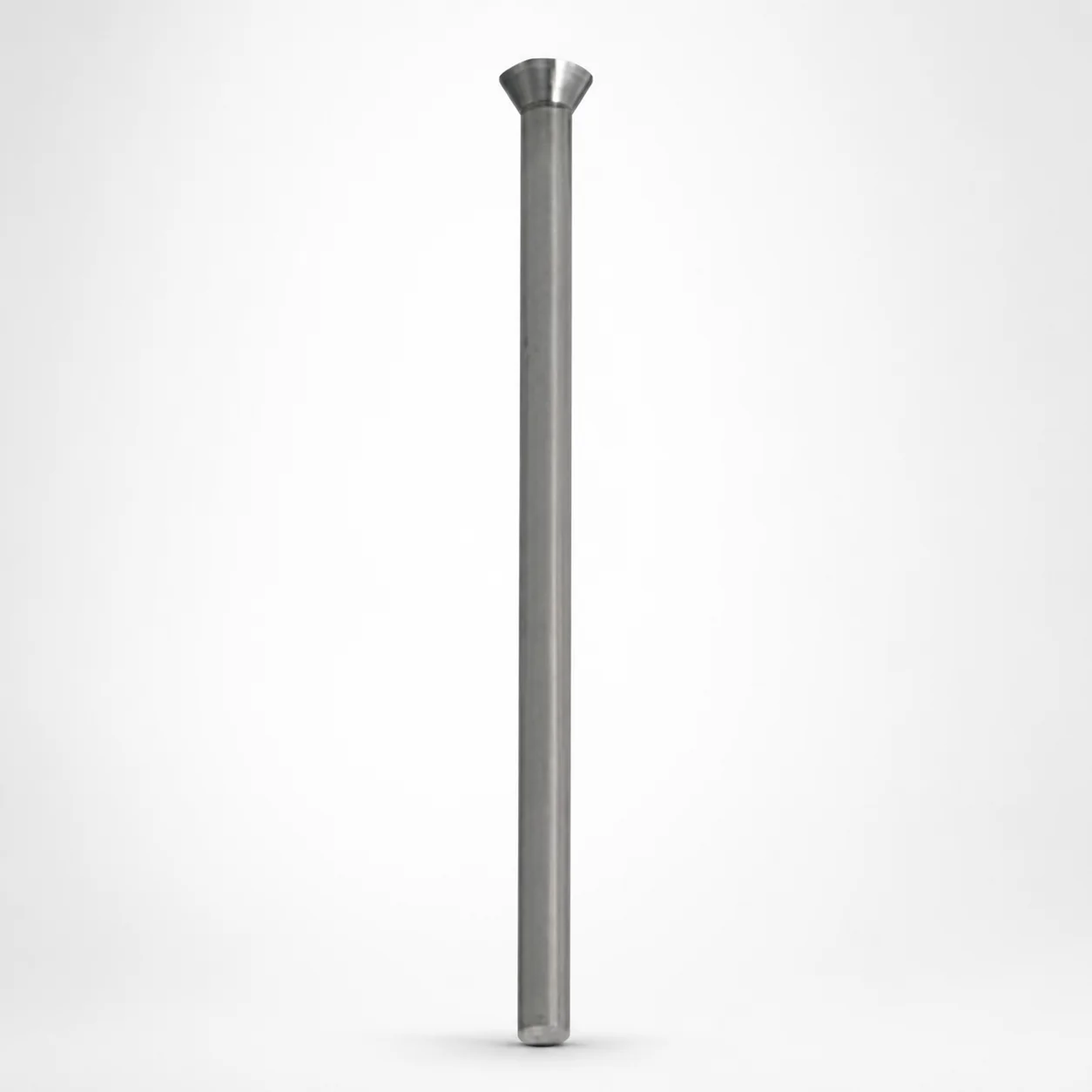
Close space straight punches - inch (XNP coating) are designed for compact die layouts where accurate punch guidance and consistent ejection are critical. The coating helps extend tooling life and maintain stable cutting performance in production.
- Close-space punch geometry supports precise alignment in tight tooling
- XNP coating enhances surface durability under repeated impacts
- Available head options for angled and regular configurations
- Commonly used in transfer dies, progressive stamping, and forming applications
Specifications
2 configurations available
| Type | L (Length) (in) | P Dimension (in) |
|---|---|---|
| Regular head - KCX | 150 ~ 400 | 0.04 ~ 0.25 |
| Angled head - KWX | 150 ~ 400 | 0.04 ~ 0.25 |
Product Guide
Application Scenarios+
Close-space straight punches are used in injection-mold-adjacent tooling such as compact die sets for progressive stamping and forming workflows, where punch guidance must stay precise under frequent cycling. The close-space geometry supports stable alignment in tight layouts, helping reduce misfeed risk and improving ejection consistency at the interface.
In automotive connector or terminal dies, angled (KWX) and regular (KCX) head options allow designers to match the punch approach angle to part geometry and strip direction. The XNP coating is selected to improve surface durability under repeated impacts and sliding, which helps maintain cutting performance over production runs.
For high-throughput transfer dies and multi-station forming operations, these punches are typically chosen to keep clearances controlled while the press forces vary across stations. This variant’s coating and guidance-oriented design make it well-suited for applications that prioritize stable tool life and consistent performance during continuous operation.
- Tight die layouts: stable punch alignment using close-space geometry
- Progressive/transfer tooling: consistent ejection and cutting behavior under repeated impacts
- KCX/KWX head configurations: match tooling approach and part/package constraints
Material & Process Details+
These close-space straight punches are supplied with an XNP coating to improve wear resistance at the punching and guidance surfaces. While the exact steel grade and heat-treatment parameters are not specified in the provided data, the coating is intended to enhance surface durability during repeated impacts and rubbing between punch and guide components.
From a materials-engineering perspective, the trade-off in coated punch tools is typically between wear resistance (better surface life) and maintaining adequate core toughness to resist chipping under load. The coating helps reduce adhesive/abrasive wear, supporting longer steady performance.
- XNP coating: improved surface durability under repetitive impacts
- Recommended use-case: where wear-driven tool life dominates over purely static abrasion
- Heat treatment: not specified—confirm internal steel grade/hardness for final design choices
If you are comparing alternatives in the same tooling class, request the underlying steel grade and stated hardness (e.g., HRC) from your tooling supplier to evaluate toughness vs. wear balance for your press forces and duty cycle.
Sizing & Selection Guide+
Select the punch length L and diameter feature P based on the mold/die stack-up and the required guidance depth. The product specifies L = 150–400 in and P = 0.04–0.25 in (range values provided). Choose L to achieve the needed engagement/support length while avoiding excessive stick-out that can increase bending stress.
For close-space tooling, match the punch guidance requirements to the die housing and guide clearance strategy. Use P to align with your local interface dimension (the data-defined diameter/feature size) so that the guided motion stays controlled throughout the press stroke.
- Step 1: Determine required support/guidance depth → select L within 150–400
- Step 2: Match the interface feature → select P within 0.04–0.25
- Step 3: Validate clearance and fit → account for coating thickness and assembly tolerance stack-up
Head configuration is variable: Regular head (KCX) and Angled head (KWX). Keep the head selection consistent with your approach geometry, then finalize L and P to the cavity/core interface requirements.
Frequently Asked Questions
Which head type should I choose for tight die layouts: Regular head (KCX) or Angled head (KWX)?+
How do I select the correct punch length L for my die stack-up?+
What does the P dimension range mean for the interface with the guide or tooling housing?+
Does the XNP coating primarily improve cutting edge life or guidance wear life?+
What tolerance considerations should I plan for when specifying these close-space punches?+
Related Products
Need Custom Specifications?
Our engineering team can help with custom configurations, material selection, and volume pricing.