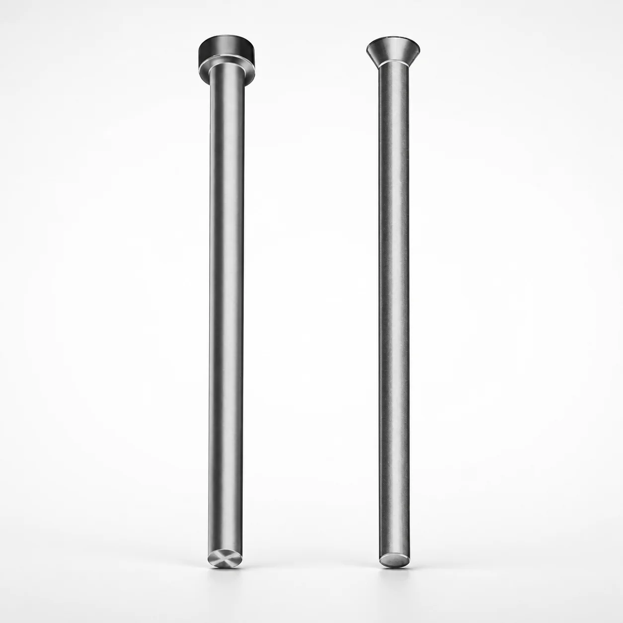
Close Space Straight Punches (Inch) XCDP Coating
Close space straight punches (Inch) with XCDP coating provide reliable guidance for precise punching operations in tight die spaces. Designed for consistent feed and stable wear behavior over repeated cycles.
- Close-space straight punch geometry supports controlled alignment in compact tooling
- XCDP coating helps improve wear resistance for longer production runs
- Available head style options support different assembly and forming requirements: angled KWX or regular KCX
- Used in press dies for punching, forming, and high-cycle stamping applications
Specifications
2 configurations available
| Type | L (Length) (in) | P Dimension (in) |
|---|---|---|
| Regular head - KCX | 150 ~ 400 | 0.04 ~ 0.25 |
| Angled head - KWX | 150 ~ 400 | 0.04 ~ 0.25 |
Product Guide
Application Scenarios+
This close-tolerance punch is used in press tooling where limited die space demands tight alignment and repeatable positioning. The straight, close-space geometry supports controlled guidance during punching so the punch tracks consistently across the stroke, helping reduce off-center loading and premature wear.
Common scenarios include automotive and general stamping dies that run high-cycle operations. Here, the XCDP coating is selected to improve wear behavior and maintain forming/punching stability over long production runs.
It is also suited for compact metal forming layouts where tool components must fit within a constrained die cavity. Engineers can choose the regular KCX head or the angled KWX head to match feed direction and assembly requirements, improving compatibility with existing punch holders and strike plates.
- Press dies for punching and forming in tight die spaces
- High-cycle stamping where stable tool life is critical
- Compact die design requiring controlled alignment
Material & Process Details+
The provided specifications focus on geometry, head type, and coating rather than disclosing a specific steel grade or numeric hardness (HRC). For this reason, the selection below is limited to what can be stated from the product data: the punch is supplied with an XCDP coating intended to improve wear resistance during repeated forming and punching cycles.
XCDP coating is typically used to reduce friction and surface degradation under cyclic loading, supporting longer tool life in press operations. The main trade-off is that coating performance depends strongly on alignment and contact conditions; close-space guidance is therefore an essential complement to achieve consistent results.
- Material grade: not specified in the provided data
- Hardness (HRC): not specified in the provided data
- Heat treatment state: not specified in the provided data
- Coating focus: XCDP for improved wear behavior
If you share the steel grade and heat-treatment state from your drawing/spec sheet, we can tailor hardness and toughness notes for your exact variant.
Sizing & Selection Guide+
To select the correct close space straight punch, match the punch length L and P dimension to your press tool layout and holder interface. This series supports L = 150 to 400 in and P = 0.04 to 0.25 in.
In practice, the L value should provide sufficient engagement within the punch holder while maintaining the required clearance in the die block. Use the available punch length range to ensure the punch does not bottom out under maximum shut height, especially in compact tooling.
The P dimension must be aligned to your close-space guidance requirement; since this is a close-space design, small deviations can affect tracking and wear. Select the KCX (regular head) or KWX (angled head) to match your feed direction and assembly geometry.
- Choose L (150–400 in) for correct engagement and stroke clearance
- Choose P (0.04–0.25 in) to meet close-space guidance needs
- Confirm compatibility with holder/strike geometry using KCX or KWX head type
Tolerance and fit: exact allowable tolerances are not provided in the data. For precise guidance performance, align the punch dimensions to your drawing’s fits and consider the effect of stack-up from holder, plate, and die block machining.
Frequently Asked Questions
When should I choose the KCX regular head vs the KWX angled head for close-space punching?+
What dimensional ranges define this inch close-space punch series?+
How does XCDP coating contribute to tool life in high-cycle stamping?+
How do I verify that the chosen L length will not cause interference at max shut height?+
What happens if P dimension is off from the close-space guidance requirement?+
Related Products
Need Custom Specifications?
Our engineering team can help with custom configurations, material selection, and volume pricing.