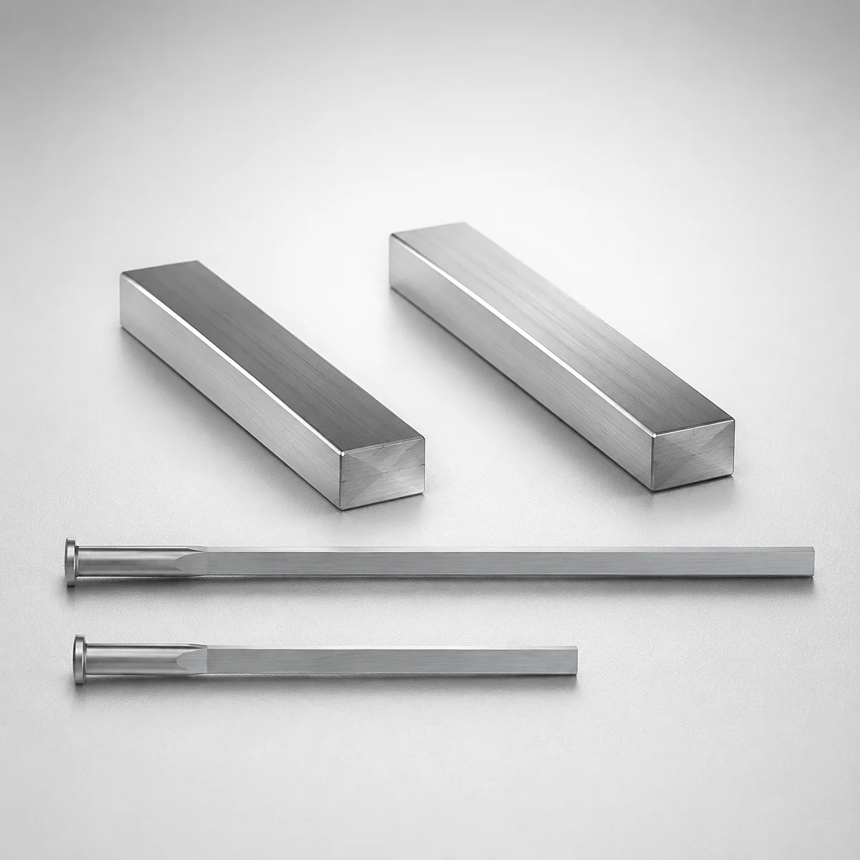
M2 Steel R-Chamfered Rectangular Ejector Pins with Engraving
R-Chamfered Rectangular Ejector Pins with Engraving (M2 steel) are designed for precise ejection in production molds, combining a chamfered rectangular tip profile with engraved identification for reliable part traceability.
- R-chamfered rectangular tip geometry (WR/FR) helps consistent alignment during ejection
- Durable M2 steel construction with quenched hardening supports long wear life
- Engraving provides clear designation by WOS for faster maintenance and setup
- Built for mold bases where stable trimming and repeatable positioning are required
Specifications
143 configurations available
| P (Tip) (mm) | W (Tip) (mm) | D (Shaft Diameter) (mm) | Character Engraving Type | Number of engraving characters | R-Chamfered Rectangular Position | L (L dimension) (mm) | Dimension N (mm) | Engraving character designation | R (Corner R of the tip corner) (mm) | type |
|---|---|---|---|---|---|---|---|---|---|---|
| 0.8 ~ 1.7 | 0.3 ~ 1.7 | 2 | Concave character | 1 characters | FR | 40 ~ 250 | 23 ~ 200 | ※Designation by WOS | 0.1 ~ 0.3 | - |
| 0.8 ~ 2.2 | 0.3 ~ 2.2 | 2.5 | Concave character | 1 characters | FR | 40 ~ 250 | 26 ~ 200 | ※Designation by WOS | 0.1 ~ 0.3 | - |
| 1 ~ 2.7 | 0.3 ~ 2.7 | 3 | Concave character | 1 characters | FR | 40 ~ 250 | 27 ~ 200 | ※Designation by WOS | 0.1 ~ 0.3 | - |
| 1 ~ 3.2 | 0.3 ~ 3.2 | 3.5 | Concave character | 1 characters | FR | 40 ~ 250 | 27 ~ 200 | ※Designation by WOS | 0.1 ~ 0.3 | - |
| 1 ~ 3.7 | 0.3 ~ 3.7 | 4 | Concave character | 1 characters | FR | 40 ~ 250 | 29 ~ 200 | ※Designation by WOS | 0.1 ~ 0.3 | - |
| 1.2 ~ 4.2 | 0.3 ~ 4.2 | 4.5 | Concave character | 1 characters | FR | 40 ~ 250 | 29 ~ 200 | ※Designation by WOS | 0.1 ~ 0.3 | - |
| 1.5 ~ 4.8 | 0.4 ~ 4.8 | 5 | Concave character | 1 characters | FR | 50 ~ 250 | 31 ~ 200 | ※Designation by WOS | 0.1 ~ 0.3 | - |
| 1.8 ~ 5.3 | 0.4 ~ 5.3 | 5.5 | Concave character | 1 characters | FR | 50 ~ 250 | 31 ~ 200 | ※Designation by WOS | 0.1 ~ 0.3 | - |
| 2 ~ 5.8 | 0.5 ~ 5.8 | 6 | Concave character | 1 characters | FR | 50 ~ 250 | 33 ~ 200 | ※Designation by WOS | 0.1 ~ 0.3 | - |
| 2 ~ 6.3 | 0.5 ~ 6.3 | 6.5 | Concave character | 1 characters | FR | 50 ~ 250 | 40 ~ 200 | ※Designation by WOS | 0.1 ~ 0.3 | - |
| 2.3 ~ 6.8 | 0.5 ~ 6.8 | 7 | Concave character | 1 characters | FR | 50 ~ 250 | 40 ~ 200 | ※Designation by WOS | 0.1 ~ 0.3 | - |
| 2.3 ~ 7.8 | 0.5 ~ 7.8 | 8 | Concave character | 1 characters | FR | 50 ~ 250 | 40 ~ 200 | ※Designation by WOS | 0.1 ~ 0.3 | - |
| 3 ~ 9.8 | 0.5 ~ 9.8 | 10 | Concave character | 1 characters | FR | 50 ~ 250 | 40 ~ 200 | ※Designation by WOS | 0.1 ~ 0.3 | - |
| 0.8 ~ 1.8 | 0.3 ~ 1.8 | 2 | Concave character (Sequential numbering) | 1 characters | FR | 50 ~ 250 | 23 ~ 200 | ※Designation by WOS | 0.1 ~ 0.3 | - |
| 0.8 ~ 2.3 | 0.3 ~ 2.3 | 2.5 | Concave character (Sequential numbering) | 1 characters | FR | 50 ~ 250 | 26 ~ 200 | ※Designation by WOS | 0.1 ~ 0.3 | - |
| 1 ~ 2.8 | 0.3 ~ 2.8 | 3 | Concave character (Sequential numbering) | 1 characters | FR | 50 ~ 250 | 27 ~ 200 | ※Designation by WOS | 0.1 ~ 0.3 | - |
| 1 ~ 3.3 | 0.3 ~ 3.3 | 3.5 | Concave character (Sequential numbering) | 1 characters | FR | 50 ~ 250 | 27 ~ 200 | ※Designation by WOS | 0.1 ~ 0.3 | - |
| 1 ~ 3.8 | 0.3 ~ 3.8 | 4 | Concave character (Sequential numbering) | 1 characters | FR | 50 ~ 250 | 29 ~ 200 | ※Designation by WOS | 0.1 ~ 0.3 | - |
| 1.2 ~ 4.3 | 0.3 ~ 4.3 | 4.5 | Concave character (Sequential numbering) | 1 characters | FR | 50 ~ 250 | 29 ~ 200 | ※Designation by WOS | 0.1 ~ 0.3 | - |
| 1.5 ~ 4.8 | 0.4 ~ 4.8 | 5 | Concave character (Sequential numbering) | 1 characters | FR | 50 ~ 250 | 31 ~ 200 | ※Designation by WOS | 0.1 ~ 0.3 | - |
| 1.8 ~ 5.3 | 0.4 ~ 5.3 | 5.5 | Concave character (Sequential numbering) | 1 characters | FR | 50 ~ 250 | 31 ~ 200 | ※Designation by WOS | 0.1 ~ 0.3 | - |
| 2 ~ 5.8 | 0.5 ~ 5.8 | 6 | Concave character (Sequential numbering) | 1 characters | FR | 50 ~ 250 | 33 ~ 200 | ※Designation by WOS | 0.1 ~ 0.3 | - |
| 2 ~ 6.3 | 0.5 ~ 6.3 | 6.5 | Concave character (Sequential numbering) | 1 characters | FR | 50 ~ 250 | 40 ~ 200 | ※Designation by WOS | 0.1 ~ 0.3 | - |
| 2.3 ~ 6.8 | 0.5 ~ 6.8 | 7 | Concave character (Sequential numbering) | 1 characters | FR | 50 ~ 250 | 40 ~ 200 | ※Designation by WOS | 0.1 ~ 0.3 | - |
| 2.3 ~ 7.8 | 0.5 ~ 7.8 | 8 | Concave character (Sequential numbering) | 1 characters | FR | 50 ~ 250 | 40 ~ 200 | ※Designation by WOS | 0.1 �� 0.3 | - |
| 3 ~ 9.8 | 0.5 ~ 9.8 | 10 | Concave character (Sequential numbering) | 1 characters | FR | 50 ~ 250 | 40 ~ 200 | ※Designation by WOS | 0.1 ~ 0.3 | - |
| 1 ~ 2.7 | 0.3 ~ 2.7 | 3 | Concave character | 2 characters | FR | 40 ~ 250 | 27 ~ 200 | ※Designation by WOS | 0.1 ~ 0.3 | - |
| 1 ~ 3.2 | 0.3 ~ 3.2 | 3.5 | Concave character | 2 characters | FR | 40 ~ 250 | 27 ~ 200 | ※Designation by WOS | 0.1 ~ 0.3 | - |
| 1 ~ 3.7 | 0.3 ~ 3.7 | 4 | Concave character | 2 characters | FR | 40 ~ 250 | 29 ~ 200 | ※Designation by WOS | 0.1 ~ 0.3 | - |
| 1.2 ~ 4.2 | 0.3 ~ 4.2 | 4.5 | Concave character | 2 characters | FR | 40 ~ 250 | 29 ~ 200 | ※Designation by WOS | 0.1 ~ 0.3 | - |
| 1.5 ~ 4.8 | 0.4 ~ 4.8 | 5 | Concave character | 2 characters | FR | 50 ~ 250 | 31 ~ 200 | ※Designation by WOS | 0.1 ~ 0.3 | - |
| 1.8 ~ 5.3 | 0.4 ~ 5.3 | 5.5 | Concave character | 2 characters | FR | 50 ~ 250 | 31 ~ 200 | ※Designation by WOS | 0.1 ~ 0.3 | - |
| 2 ~ 5.8 | 0.5 ~ 5.8 | 6 | Concave character | 2 characters | FR | 50 ~ 250 | 33 ~ 200 | ※Designation by WOS | 0.1 ~ 0.3 | - |
| 2 ~ 6.3 | 0.5 ~ 6.3 | 6.5 | Concave character | 2 characters | FR | 50 ~ 250 | 40 ~ 200 | ※Designation by WOS | 0.1 ~ 0.3 | - |
| 2.3 ~ 6.8 | 0.5 ~ 6.8 | 7 | Concave character | 2 characters | FR | 50 ~ 250 | 40 ~ 200 | ※Designation by WOS | 0.1 ~ 0.3 | - |
| 2.3 ~ 7.8 | 0.5 ~ 7.8 | 8 | Concave character | 2 characters | FR | 50 ~ 250 | 40 ~ 200 | ※Designation by WOS | 0.1 ~ 0.3 | - |
| 3 ~ 9.8 | 0.5 ~ 9.8 | 10 | Concave character | 2 characters | FR | 50 ~ 250 | 40 ~ 200 | ※Designation by WOS | 0.1 ~ 0.3 | - |
| 1 ~ 2.8 | 0.3 ~ 2.8 | 3 | Concave character (Sequential numbering) | 2 characters | FR | 50 ~ 250 | 27 ~ 200 | ※Designation by WOS | 0.1 ~ 0.3 | - |
| 1 ~ 3.3 | 0.3 ~ 3.3 | 3.5 | Concave character (Sequential numbering) | 2 characters | FR | 50 ~ 250 | 27 ~ 200 | ※Designation by WOS | 0.1 ~ 0.3 | - |
| 1 ~ 3.8 | 0.3 ~ 3.8 | 4 | Concave character (Sequential numbering) | 2 characters | FR | 50 ~ 250 | 29 ~ 200 | ※Designation by WOS | 0.1 ~ 0.3 | - |
| 1.2 ~ 4.3 | 0.3 ~ 4.3 | 4.5 | Concave character (Sequential numbering) | 2 characters | FR | 50 ~ 250 | 29 ~ 200 | ※Designation by WOS | 0.1 ~ 0.3 | - |
| 1.5 ~ 4.8 | 0.4 ~ 4.8 | 5 | Concave character (Sequential numbering) | 2 characters | FR | 50 ~ 250 | 31 ~ 200 | ※Designation by WOS | 0.1 ~ 0.3 | - |
| 1.8 ~ 5.3 | 0.4 ~ 5.3 | 5.5 | Concave character (Sequential numbering) | 2 characters | FR | 50 ~ 250 | 31 ~ 200 | ※Designation by WOS | 0.1 ~ 0.3 | - |
| 2 ~ 5.8 | 0.5 ~ 5.8 | 6 | Concave character (Sequential numbering) | 2 characters | FR | 50 ~ 250 | 33 ~ 200 | ※Designation by WOS | 0.1 ~ 0.3 | - |
| 2 ~ 6.3 | 0.5 ~ 6.3 | 6.5 | Concave character (Sequential numbering) | 2 characters | FR | 50 ~ 250 | 40 ~ 200 | ※Designation by WOS | 0.1 ~ 0.3 | - |
| 2.3 ~ 6.8 | 0.5 ~ 6.8 | 7 | Concave character (Sequential numbering) | 2 characters | FR | 50 ~ 250 | 40 ~ 200 | ※Designation by WOS | 0.1 ~ 0.3 | - |
| 2.3 ~ 7.8 | 0.5 ~ 7.8 | 8 | Concave character (Sequential numbering) | 2 characters | FR | 50 ~ 250 | 40 ~ 200 | ※Designation by WOS | 0.1 ~ 0.3 | - |
| 3 ~ 9.8 | 0.5 ~ 9.8 | 10 | Concave character (Sequential numbering) | 2 characters | FR | 50 ~ 250 | 40 ~ 200 | ※Designation by WOS | 0.1 ~ 0.3 | - |
| 1 ~ 3.2 | 0.3 ~ 3.2 | 3.5 | Concave character | 3 characters | FR | 40 ~ 250 | 27 ~ 200 | ※Designation by WOS | 0.1 ~ 0.3 | - |
| 1 ~ 3.7 | 0.3 ~ 3.7 | 4 | Concave character | 3 characters | FR | 40 ~ 250 | 29 ~ 200 | ※Designation by WOS | 0.1 ~ 0.3 | - |
Product Guide
Application Scenarios+
These R-chamfered rectangular ejector pins with engraved identification are used in injection mold build-ups where repeatable trimming and dependable ejection are required. The FR/WR chamfered rectangular tip geometry supports stable alignment as the pin advances, helping reduce mis-trap risk on the ejecting stroke.
They are well-suited for automotive connector and housing molds, where high cycle rates demand consistent ejection and durable wear resistance at the pin tip. The M2 tool steel construction helps maintain hardness under typical molding loads.
They also fit consumer electronics enclosure molds that require fast setup and maintenance. The concave engraved character (※Designation by WOS) enables clear pin identification for routine inspection and replacement planning.
- Use in ejector-blade/ejector pin assemblies to standardize trimming and positioning
- Engraving supports traceability across multi-cavity tool maintenance
Material & Process Details+
This component is specified in M2 steel, a high-speed steel grade commonly used for tooling requiring strong wear resistance. In M2 equivalents, the material is typically associated with AISI M2 performance characteristics, balancing hardness with manageable toughness for ejection hardware.
- Wear resistance: M2 supports long service life at sliding contact points such as chamfered rectangular tips.
- Toughness trade-off: as hardness increases, impact toughness generally decreases; proper design for pin loading and ejection force is important.
Because the build spec provided here focuses on geometry and identification, the exact heat-treatment state (e.g., quenched & tempered or nitrided) is not numerically specified. However, the design intent is consistent with quenched hardening for hard wear performance in mold duty.
Sizing & Selection Guide+
Select the pin based on the mold’s ejector system geometry and the cavity/core clearance needed around the parting and ejecting surfaces. Start with the shaft diameter D in the range 2 ~ 10 mm to match the ejector guide and the receiving features in your mold base.
Then choose the rectangular tip profile using P (tip) 0.8 ~ 3 mm and W (tip) 0.3 ~ 0.5 mm. The tip chamfer corner radius R is available at 0.1 ~ 0.3 mm, which helps guide alignment during ejection.
Match the installed length using L = 40 ~ 250 mm (or the alternate range 50 ~ 250 mm as offered) and verify clearance using the dimension N = 23 ~ 40 mm.
- Confirm R-chamfered rectangular position: FR or WR to align with your mold’s ejection direction and part geometry.
- Engraving character count (1–5) is configurable, but does not change critical fit dimensions.
Frequently Asked Questions
How do I select between FR and WR R-chamfered rectangular positions for ejector blade assemblies?+
What tip dimensions (P, W, and R) should I use to control alignment and contact at the ejection area?+
How do I match the ejector pin shaft diameter D and length L to the mold build-up receiving features?+
Is the engraving character designation compatible with sequential pin identification for maintenance?+
What material advantages does M2 steel provide for ejector pins under high-cycle injection molding?+
Related Products
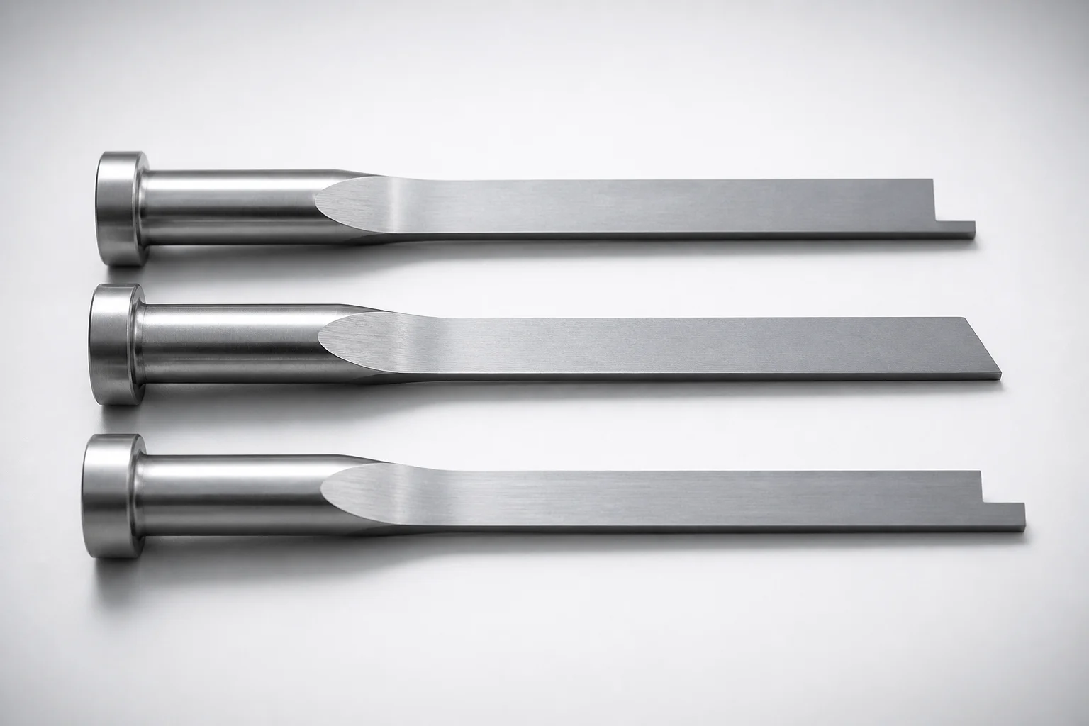
JIS Standard SKH51 Steel Precision Rectangular Ejector Pins with Tip Processed
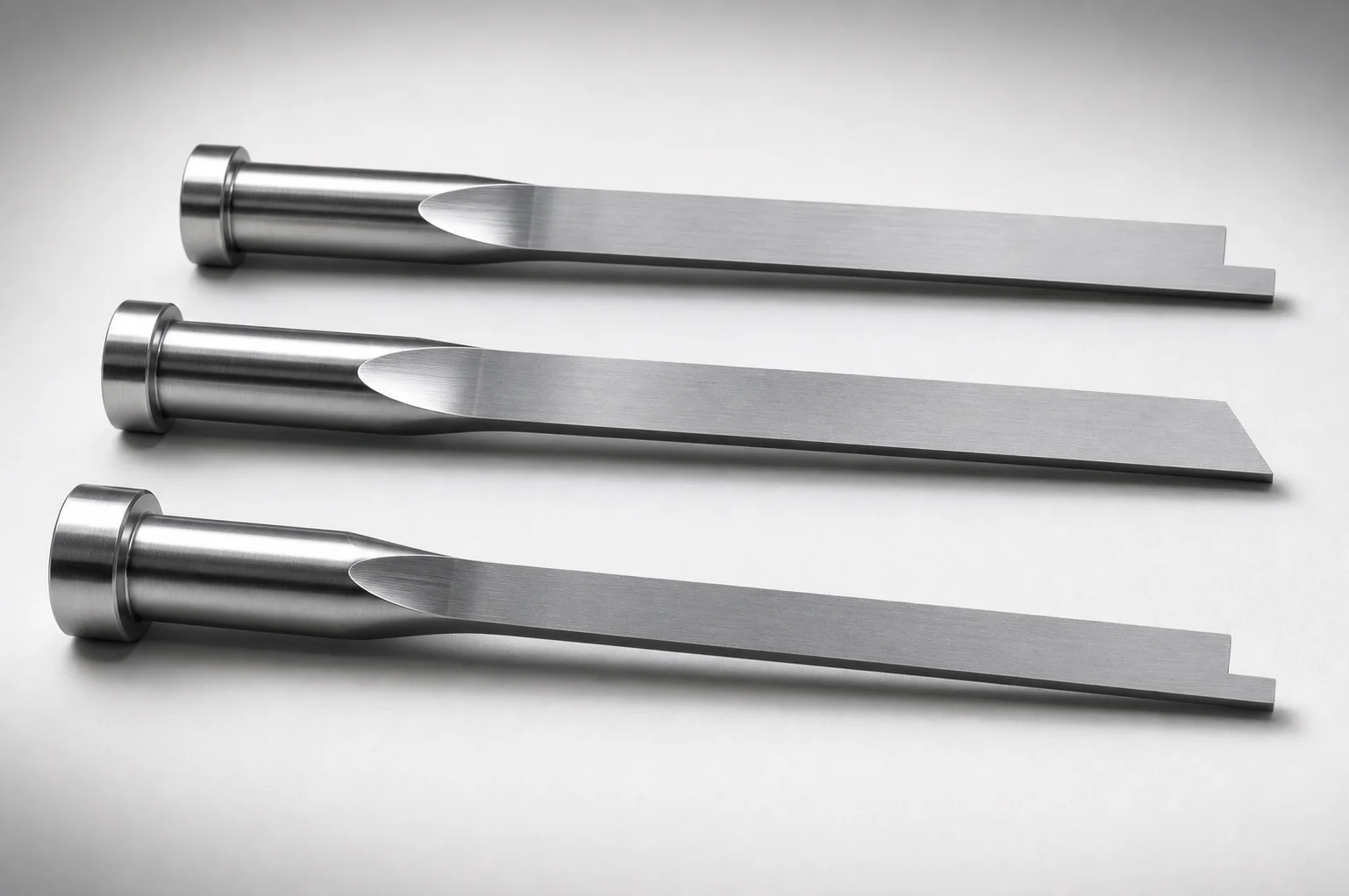
JIS Standard SKH51 Steel Tip-Processed Rectangular Ejector Pins
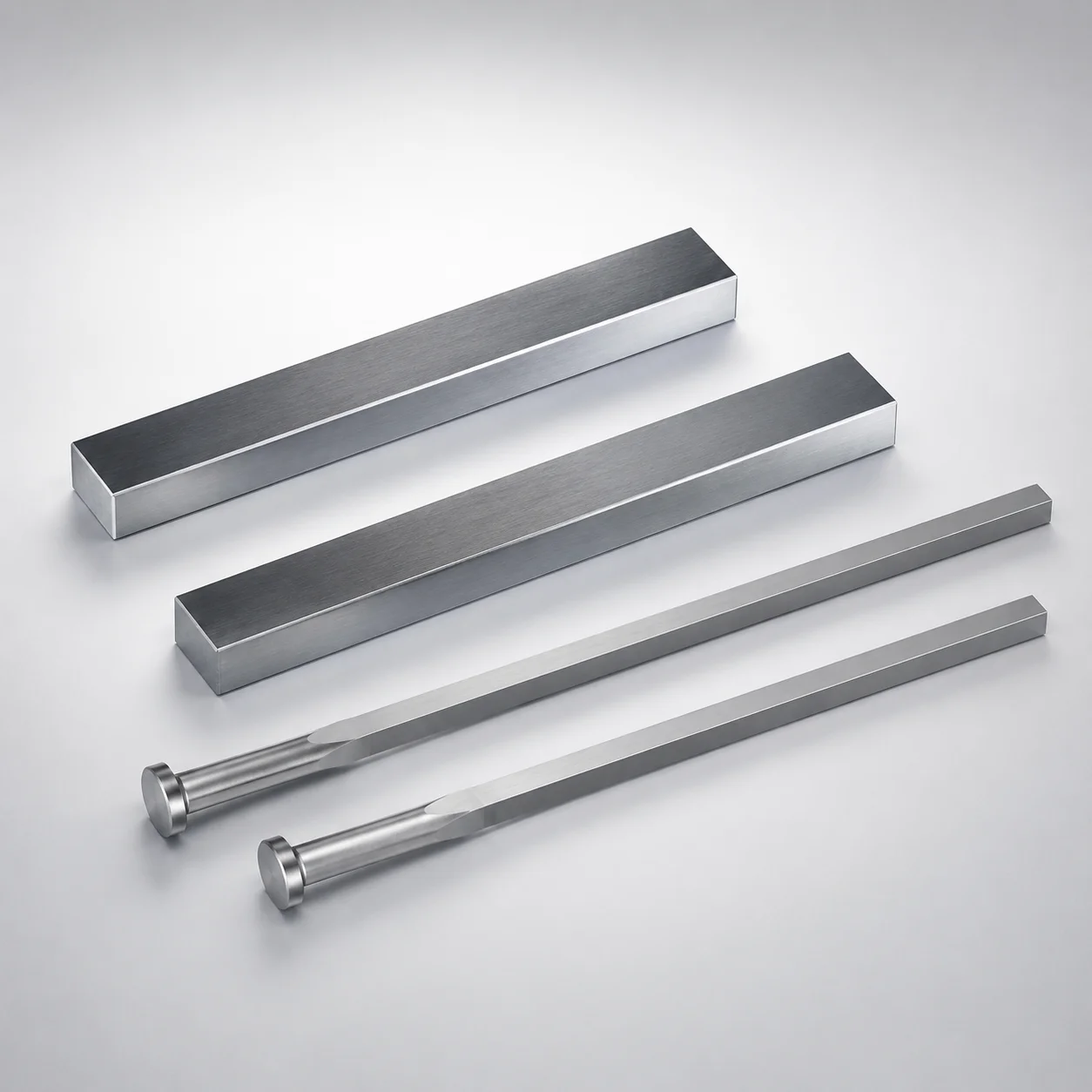
JIS Standard SKH51 Steel Rectangular Ejector Pins with Engraving
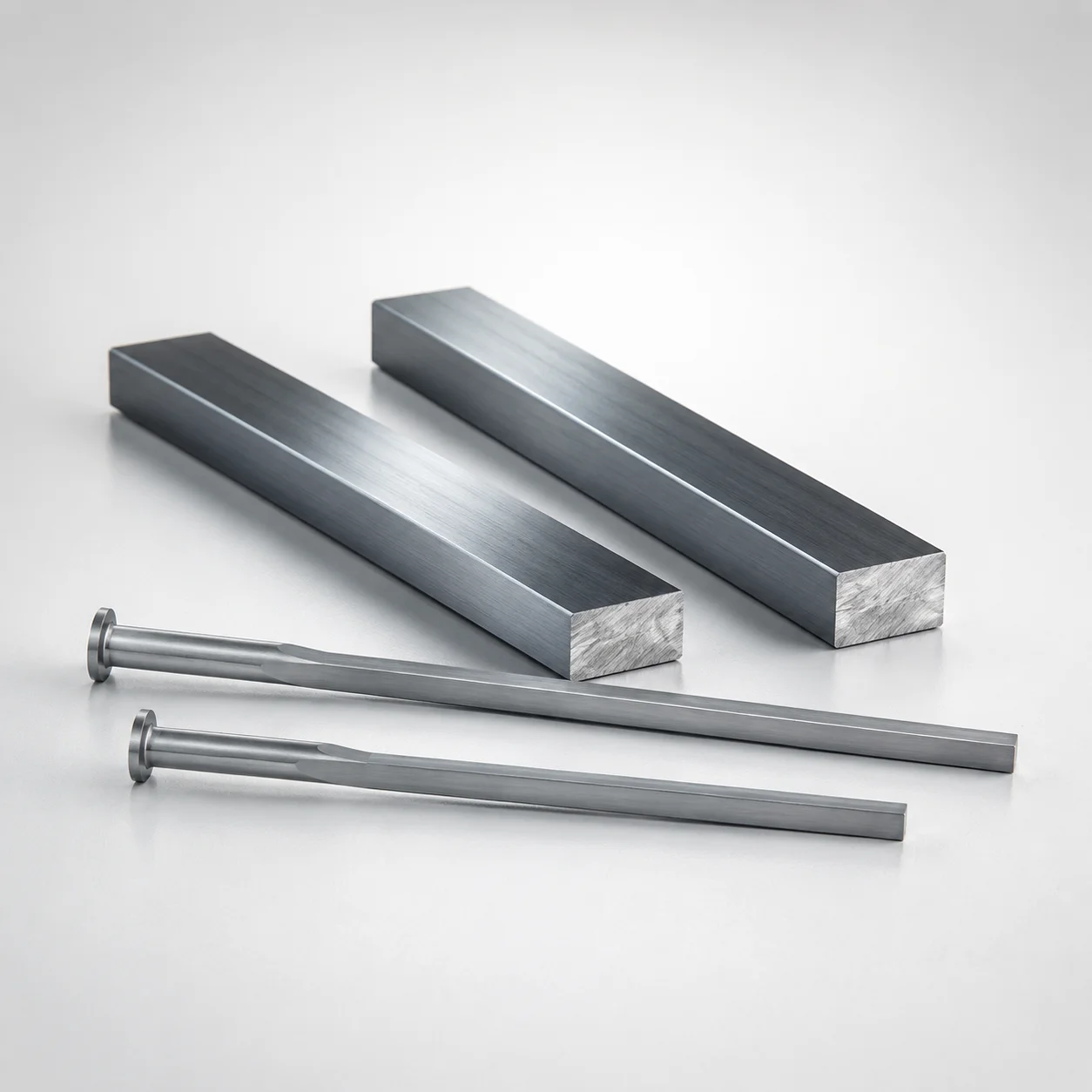
M2 Steel Rectangular Ejector Pins with Engraving - Flat-Head
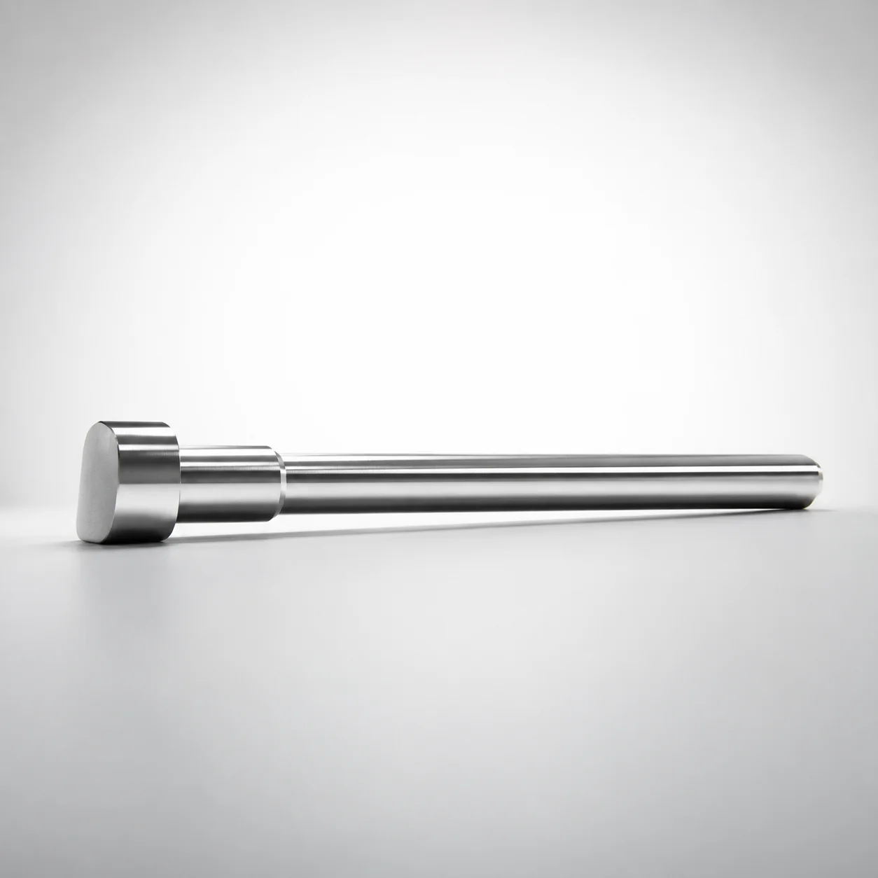
JIS Standard SKH51 Steel D-Shaped Ejector Pins
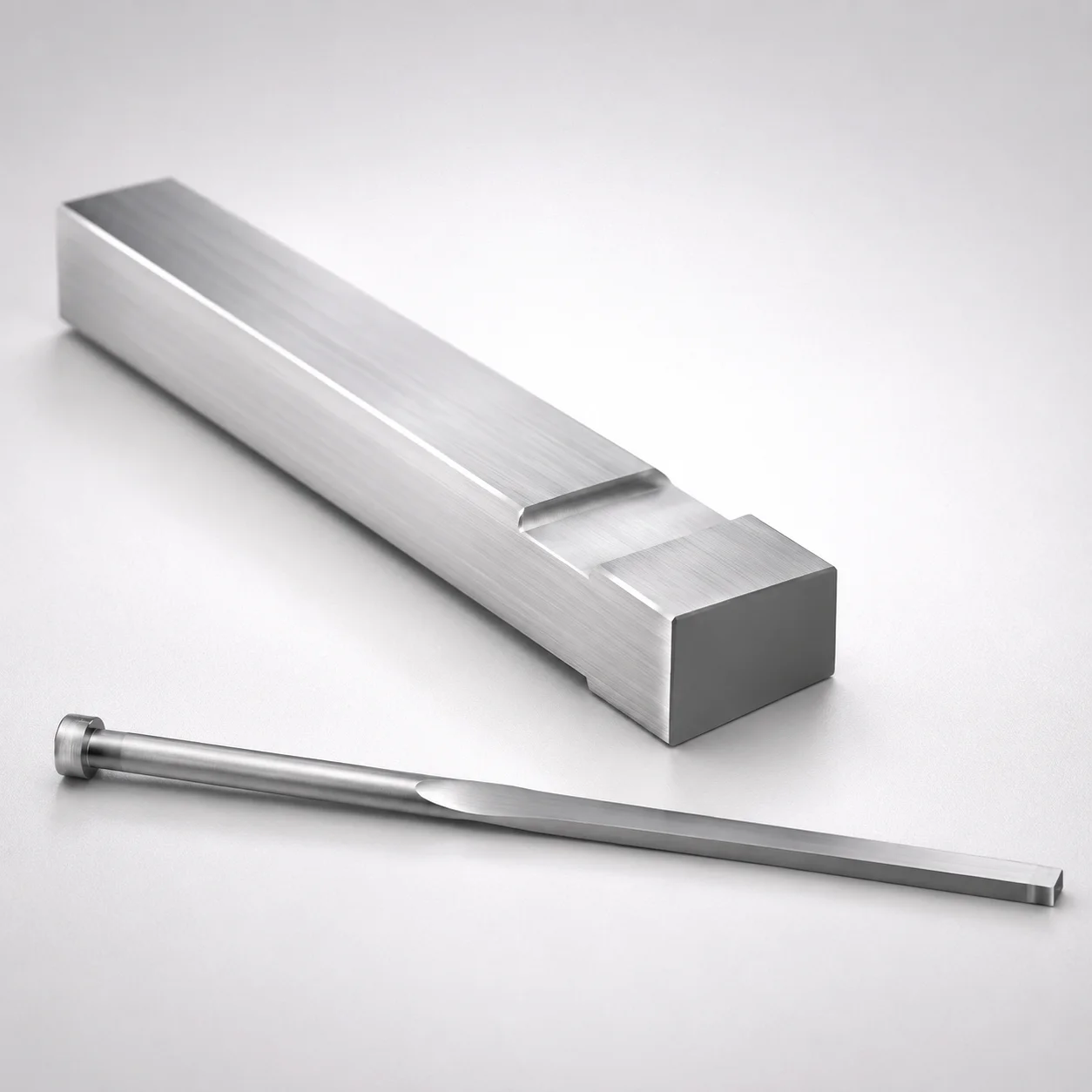
JIS Standard M2 Steel Gas Release Rectangular Ejector Pins
Need Custom Specifications?
Our engineering team can help with custom configurations, material selection, and volume pricing.