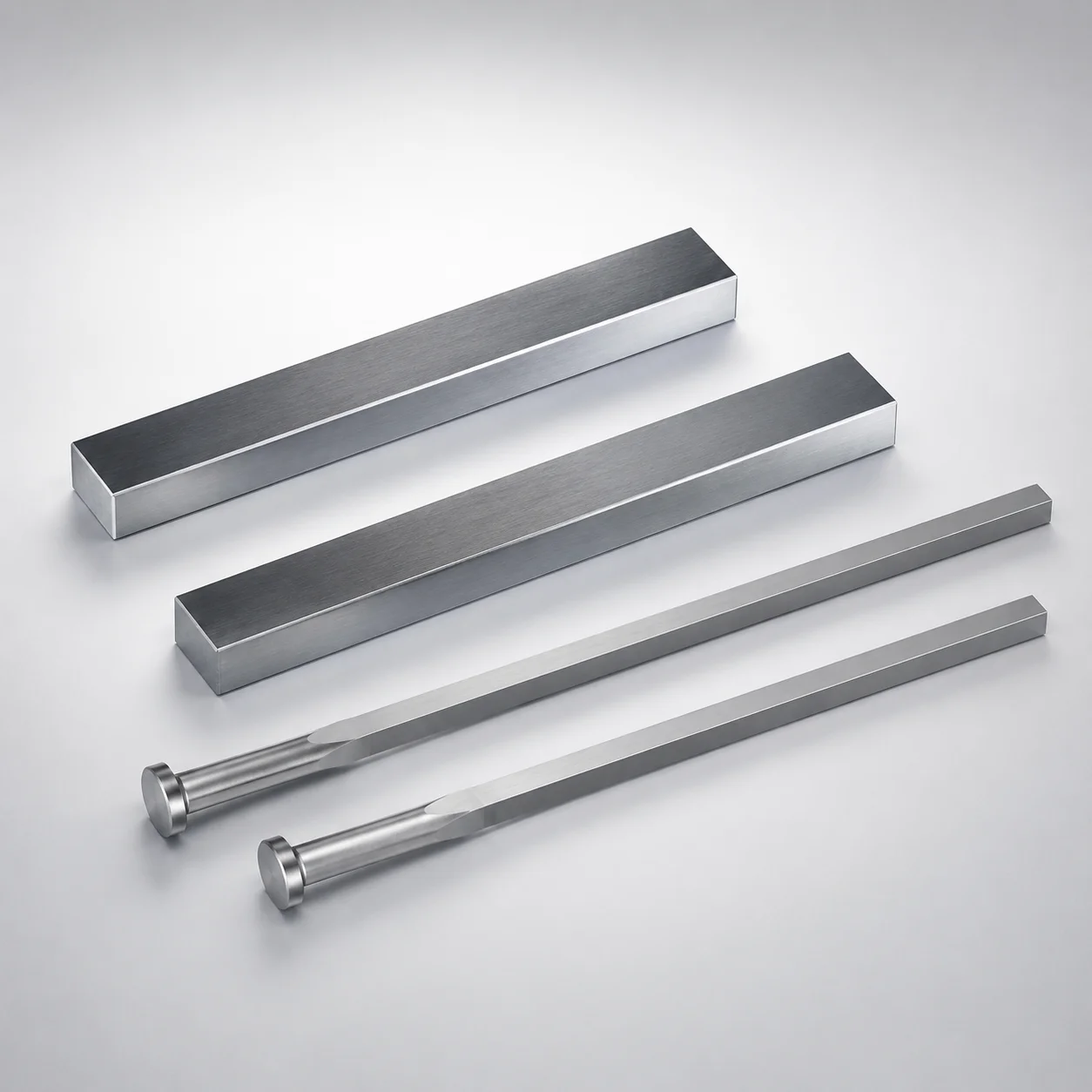
JIS Standard SKH51 Steel Rectangular Ejector Pins with Engraving
Rectangular ejector pins with engraving (SKH51 steel) are precision mold components designed to add identification engraving while maintaining stable rectangular guidance for consistent ejection performance. They are suitable for demanding die and mold builds.
- Engraved identification with WOS designation helps traceability during mold maintenance
- SKH51 steel and controlled manufacturing support strong wear resistance in repeated cycles
- Head thickness T=4 mm provides a robust bearing area for reliable installation
- P/W dimension control (0/-0.005) supports tight fit for precise ejector layout
Specifications
86 configurations available
| P (Tip) (mm) | W (Tip) (mm) | D (Shaft Diameter) (mm) | Character Engraving Type | Number of engraving characters | L (L dimension) (mm) | Dimension N (mm) | Engraving character designation | type |
|---|---|---|---|---|---|---|---|---|
| 0.8 ~ 1.7 | 0.3 ~ 1.6 | 2 | Concave character | 1 characters | 40 ~ 250 | 23 ~ 240 | ※Designation by WOS | - |
| 0.8 ~ 2.2 | 0.3 ~ 2.1 | 2.5 | Concave character | 1 characters | 40 ~ 250 | 26 ~ 240 | ※Designation by WOS | - |
| 1 ~ 2.7 | 0.3 ~ 2.7 | 3 | Concave character | 1 characters | 40 ~ 250 | 27 ~ 240 | ※Designation by WOS | - |
| 1 ~ 3.2 | 0.3 ~ 3.2 | 3.5 | Concave character | 1 characters | 40 ~ 250 | 27 ~ 240 | ※Designation by WOS | - |
| 1 ~ 3.7 | 0.7 ~ 3.7 | 4 | Concave character | 1 characters | 40 ~ 250 | 29 ~ 240 | ※Designation by WOS | - |
| 1.2 ~ 4.2 | 0.7 ~ 4.2 | 4.5 | Concave character | 1 characters | 40 ~ 250 | 29 ~ 240 | ※Designation by WOS | - |
| 1.5 ~ 4.8 | 0.7 ~ 4.66 | 5 | Concave character | 1 characters | 50 ~ 250 | 31 ~ 240 | ※Designation by WOS | - |
| 1.8 ~ 5.3 | 0.7 ~ 5.09 | 5.5 | Concave character | 1 characters | 50 ~ 250 | 31 ~ 240 | ※Designation by WOS | - |
| 2 ~ 5.8 | 0.7 ~ 5.5 | 6 | Concave character | 1 characters | 50 ~ 250 | 33 ~ 240 | ※Designation by WOS | - |
| 2 ~ 6.3 | 0.7 ~ 6.07 | 6.5 | Concave character | 1 characters | 50 ~ 250 | 40 ~ 240 | ※Designation by WOS | - |
| 2.3 ~ 6.8 | 0.7 ~ 6.43 | 7 | Concave character | 1 characters | 50 ~ 250 | 40 ~ 240 | ※Designation by WOS | - |
| 2.3 ~ 7.8 | 0.7 ~ 7.49 | 8 | Concave character | 1 characters | 50 ~ 250 | 40 ~ 240 | ※Designation by WOS | - |
| 2.3 ~ 8.3 | 0.7 ~ 8.07 | 8.5 | Concave character | 1 characters | 50 ~ 250 | 40 ~ 240 | ※Designation by WOS | - |
| 3 ~ 9.8 | 0.7 ~ 9.43 | 10 | Concave character | 1 characters | 50 ~ 250 | 40 ~ 240 | ※Designation by WOS | - |
| 3 ~ 10.3 | 0.7 ~ 9.95 | 10.5 | Concave character | 1 characters | 50 ~ 250 | 40 ~ 240 | ※Designation by WOS | - |
| 0.8 ~ 1.7 | 0.3 ~ 1.7 | 2 | Concave character (Sequential numbering) | 1 characters | 40 ~ 250 | 23 ~ 240 | ※Designation by WOS | - |
| 0.8 ~ 2.2 | 0.3 ~ 2.2 | 2.5 | Concave character (Sequential numbering) | 1 characters | 40 ~ 250 | 26 ~ 240 | ※Designation by WOS | - |
| 1 ~ 2.7 | 0.3 ~ 2.7 | 3 | Concave character (Sequential numbering) | 1 characters | 40 ~ 250 | 27 ~ 240 | ※Designation by WOS | - |
| 1 ~ 3.2 | 0.3 ~ 3.2 | 3.5 | Concave character (Sequential numbering) | 1 characters | 40 ~ 250 | 27 ~ 240 | ※Designation by WOS | - |
| 1 ~ 3.7 | 0.3 ~ 3.7 | 4 | Concave character (Sequential numbering) | 1 characters | 40 ~ 250 | 29 ~ 240 | ※Designation by WOS | - |
| 1.2 ~ 4.2 | 0.3 ~ 4.2 | 4.5 | Concave character (Sequential numbering) | 1 characters | 40 ~ 250 | 29 ~ 240 | ※Designation by WOS | - |
| 1.5 ~ 4.8 | 0.4 ~ 4.8 | 5 | Concave character (Sequential numbering) | 1 characters | 50 ~ 250 | 31 ~ 240 | ※Designation by WOS | - |
| 1.8 ~ 5.3 | 0.4 ~ 5.3 | 5.5 | Concave character (Sequential numbering) | 1 characters | 50 ~ 250 | 31 ~ 240 | ※Designation by WOS | - |
| 2 ~ 5.8 | 0.5 ~ 5.8 | 6 | Concave character (Sequential numbering) | 1 characters | 50 ~ 250 | 33 ~ 240 | ※Designation by WOS | - |
| 2 ~ 6.3 | 0.5 ~ 6.3 | 6.5 | Concave character (Sequential numbering) | 1 characters | 50 ~ 250 | 40 ~ 240 | ※Designation by WOS | - |
| 2.3 ~ 6.8 | 0.5 ~ 6.8 | 7 | Concave character (Sequential numbering) | 1 characters | 50 ~ 250 | 40 ~ 240 | ※Designation by WOS | - |
| 2.3 ~ 7.8 | 0.5 ~ 7.8 | 8 | Concave character (Sequential numbering) | 1 characters | 50 ~ 250 | 40 ~ 240 | ※Designation by WOS | - |
| 2.3 ~ 8.3 | 0.7 ~ 8.07 | 8.5 | Concave character (Sequential numbering) | 1 characters | 50 ~ 250 | 40 ~ 240 | ※Designation by WOS | - |
| 3 ~ 9.8 | 0.5 ~ 9.8 | 10 | Concave character (Sequential numbering) | 1 characters | 50 ~ 250 | 40 ~ 240 | ※Designation by WOS | - |
| 3 ~ 10.3 | 0.7 ~ 9.95 | 10.5 | Concave character (Sequential numbering) | 1 characters | 50 ~ 250 | 40 ~ 240 | ※Designation by WOS | - |
| 2.3 ~ 2.7 | 0.7 ~ 2.7 | 3 | Concave character | 2 characters | 40 ~ 250 | 27 ~ 240 | ※Designation by WOS | - |
| 2.3 ~ 3.2 | 0.7 ~ 3.2 | 3.5 | Concave character | 2 characters | 40 ~ 250 | 27 ~ 240 | ※Designation by WOS | - |
| 2.3 ~ 3.7 | 0.7 ~ 3.7 | 4 | Concave character | 2 characters | 40 ~ 250 | 29 ~ 240 | ※Designation by WOS | - |
| 2.3 ~ 4.2 | 0.7 ~ 4.2 | 4.5 | Concave character | 2 characters | 40 ~ 250 | 29 ~ 240 | ※Designation by WOS | - |
| 2.3 ~ 4.8 | 0.7 ~ 4.66 | 5 | Concave character | 2 characters | 50 ~ 250 | 31 ~ 240 | ※Designation by WOS | - |
| 2.3 ~ 5.3 | 0.7 ~ 5.09 | 5.5 | Concave character | 2 characters | 50 ~ 250 | 31 ~ 240 | ※Designation by WOS | - |
| 2.3 ~ 5.8 | 0.7 ~ 5.5 | 6 | Concave character | 2 characters | 50 ~ 250 | 33 ~ 240 | ※Designation by WOS | - |
| 2.3 ~ 6.3 | 0.7 ~ 6.07 | 6.5 | Concave character | 2 characters | 50 ~ 250 | 40 ~ 240 | ※Designation by WOS | - |
| 2.3 ~ 6.8 | 0.7 ~ 6.43 | 7 | Concave character | 2 characters | 50 ~ 250 | 40 ~ 240 | ※Designation by WOS | - |
| 2.3 ~ 7.8 | 0.7 ~ 7.49 | 8 | Concave character | 2 characters | 50 ~ 250 | 40 ~ 240 | ※Designation by WOS | - |
| 2.3 ~ 8.3 | 0.7 ~ 8.07 | 8.5 | Concave character | 2 characters | 50 ~ 250 | 40 ~ 240 | ※Designation by WOS | - |
| 3 ~ 9.8 | 0.7 ~ 9.43 | 10 | Concave character | 2 characters | 50 ~ 250 | 40 ~ 240 | ※Designation by WOS | - |
| 3 ~ 10.3 | 0.7 ~ 9.95 | 10.5 | Concave character | 2 characters | 50 ~ 250 | 40 ~ 240 | ※Designation by WOS | - |
| 1 ~ 2.7 | 0.3 ~ 2.7 | 3 | Concave character (Sequential numbering) | 2 characters | 40 ~ 250 | 27 ~ 240 | ※Designation by WOS | - |
| 1 ~ 3.2 | 0.3 ~ 3.2 | 3.5 | Concave character (Sequential numbering) | 2 characters | 40 ~ 250 | 27 ~ 240 | ※Designation by WOS | - |
| 1 ~ 3.7 | 0.3 ~ 3.7 | 4 | Concave character (Sequential numbering) | 2 characters | 40 ~ 250 | 29 ~ 240 | ※Designation by WOS | - |
| 1.2 ~ 4.2 | 0.3 ~ 4.2 | 4.5 | Concave character (Sequential numbering) | 2 characters | 40 ~ 250 | 29 ~ 240 | ※Designation by WOS | - |
| 1.5 ~ 4.8 | 0.4 ~ 4.8 | 5 | Concave character (Sequential numbering) | 2 characters | 50 ~ 250 | 31 ~ 240 | ※Designation by WOS | - |
| 1.8 ~ 5.3 | 0.4 ~ 5.3 | 5.5 | Concave character (Sequential numbering) | 2 characters | 50 ~ 250 | 31 ~ 240 | ※Designation by WOS | - |
| 2 ~ 5.8 | 0.5 ~ 5.8 | 6 | Concave character (Sequential numbering) | 2 characters | 50 ~ 250 | 33 ~ 240 | ※Designation by WOS | - |
Product Guide
Application Scenarios+
Where they’re used: These rectangular ejector pins are built into injection mold ejector systems where accurate alignment and repeatable ejection force matter. The engraved characters support component identification during assembly, maintenance, or changeover—especially in multi-cavity tooling.
Scenario 1 – Automotive connector housings: In connector and small electronic-part housings, stable rectangular guidance helps prevent pin skew under cyclic ejection. The SKH51 variant is suited for frequent cycles where wear resistance at the pin/contact surfaces supports consistent ejector behavior.
Scenario 2 – Medical device housings: For molded housings requiring traceable tooling parts, the WOS-based designation engraving enables field-level identification. Concave engraving (including sequential numbering) is practical when multiple similar ejector components must be distinguished.
Scenario 3 – Precision consumer electronics inserts: The controlled P/W fit range supports tight ejector layout, reducing misalignment risk that can otherwise cause uneven stripping.
- Rectangular guidance improves alignment during ejection
- Engraving improves traceability for mold maintenance
- SKH51 supports durability under repeated cycles
Material & Process Details+
Steel grade: JIS Standard SKH51 (high-speed steel) is used for ejector pin applications requiring elevated wear resistance. In common industry cross-references, SKH51 is often associated with the AISI M2 family due to its high-carbon, high-alloy HSS character.
Material performance: With appropriate heat treatment, SKH51 provides a favorable balance of wear resistance and toughness. In ejector systems, the trade-off is typical of HSS tools: pushing hardness improves abrasion resistance but requires careful control of toughness to avoid chipping under shock loads.
- Heat treatment state (typical for SKH51 ejector pins): quenched and tempered to achieve target hardness for service
- Hardness: exact HRC value is not provided in the specification data; hardness should be validated to match your expected ejection pressure and wear conditions
- Manufacturing: precision machining for rectangular guidance geometry and controlled dimensioning for the P/W fit
If alternative steels are offered for the same geometry, SKH51 is typically selected when wear resistance is prioritized over maximum shock toughness.
Sizing & Selection Guide+
Step 1: Match the shaft diameter and tip geometry. Select the ejector pin size based on D (shaft diameter) = 2 ~ 10.5 mm, then choose P (Tip) = 0.8 ~ 5 mm and W (Tip) = 0.3 ~ 0.7 mm within the available ranges for your ejector layout.
Step 2: Confirm length for travel requirements. Use L (L dimension) = 40 ~ 250 mm or the listed alternate range (50 ~ 250 mm) when applicable. The pin length should cover the expected stroke and allow secure engagement in the ejector support structure.
Step 3: Validate the rectangular guidance fit. The data indicates P/W dimension control (0 / -0.005), meaning the fit may be up to nominal and slightly undersize by 0.005 mm. Ensure your mating ejector block/core pocket design accounts for this tolerance to avoid looseness or binding.
- Dimension N = 23 ~ 40 mm should align with your guidance/support geometry
- Character engraving is fixed as WOS designation, so it doesn’t change the critical fit dimensions
- Verify that the total ejector stack height accommodates L and N
Frequently Asked Questions
What SKH51 hardness and heat-treatment condition is used for these rectangular ejector pins?+
The provided data specifies JIS Standard SKH51 steel and describes controlled manufacturing for wear resistance, but it does not include a specific hardness value (HRC) or the exact heat-treatment cycle. For qualification, request the heat-treatment report for the target HRC and confirm whether the pins are quenched & tempered (typical for SKH51) to your required service conditions.
How do I select the correct pin size using the P, W, and D ranges for my ejector layout?+
Use D = 2 ~ 10.5 mm for the shaft interface, and choose tip geometry within P = 0.8 ~ 5 mm and W = 0.3 ~ 0.7 mm. Then design your mating rectangular guidance features to the required fit considering the stated P/W dimension control (0 / -0.005), which allows slight undersize by up to 0.005 mm.
What engraving options are available, and how does the WOS designation affect mold assembly traceability?+
These pins use concave character engraving, including concave character (Sequential numbering). The engraving character designation is fixed as ※Designation by WOS, supporting traceability during mold maintenance; the available engraving character counts are 1 to 5 characters.
What length options should I use for expected ejector travel and clearance?+
The specification lists L = 40 ~ 250 mm and also L = 50 ~ 250 mm as applicable options. Select L so the pin covers the required stroke and maintains adequate engagement and clearance within your ejector support system while matching the guidance geometry defined by N = 23 ~ 40 mm.
Are these pins intended for high-cycle wear conditions, or are they mainly for alignment?+
They are selected for both: stable rectangular guidance supports accurate ejection and alignment, and the SKH51 steel selection is tied to repeated-cycle wear performance. If your application has frequent ejection cycles, prioritize the SKH51 wear-resistance characteristics and confirm fit/tolerance with the stated P/W control to maintain alignment over time.
Related Products
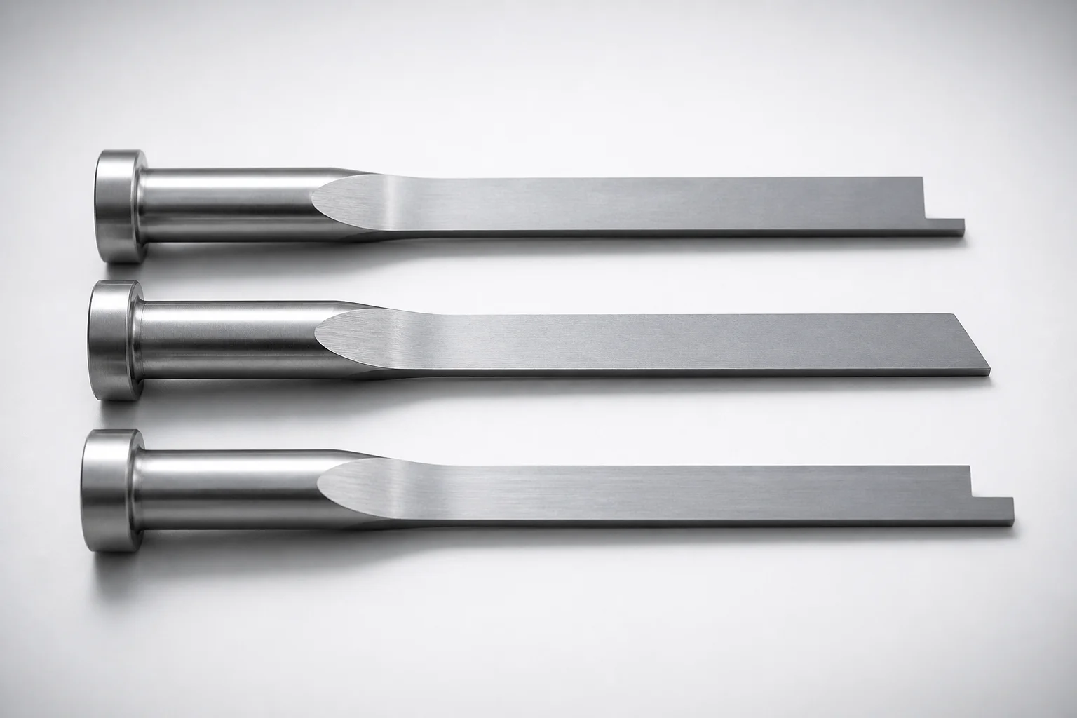
JIS Standard SKH51 Steel Precision Rectangular Ejector Pins with Tip Processed
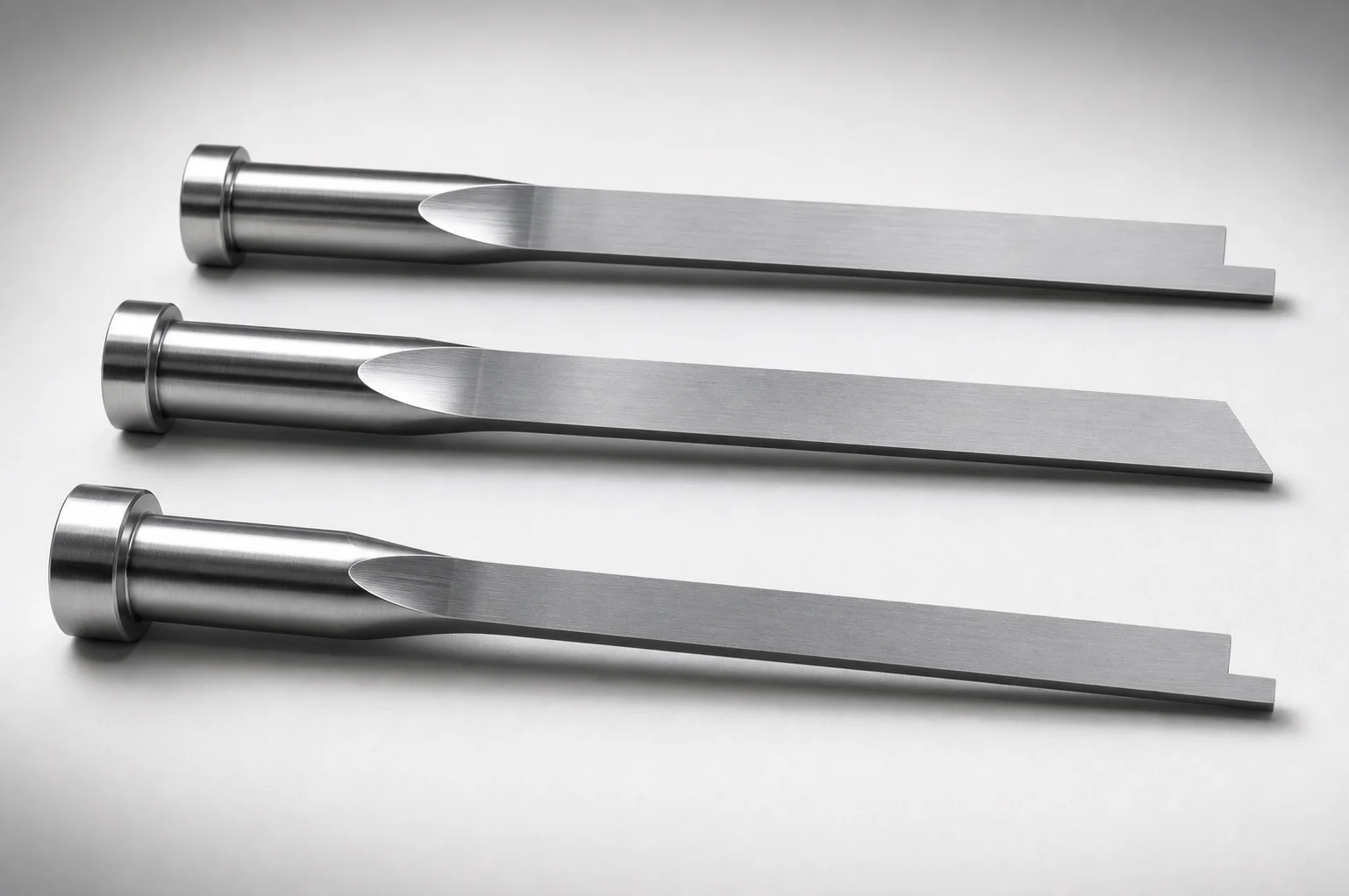
JIS Standard SKH51 Steel Tip-Processed Rectangular Ejector Pins
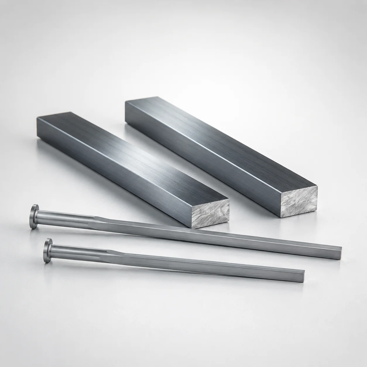
M2 Steel Rectangular Ejector Pins with Engraving - Flat-Head
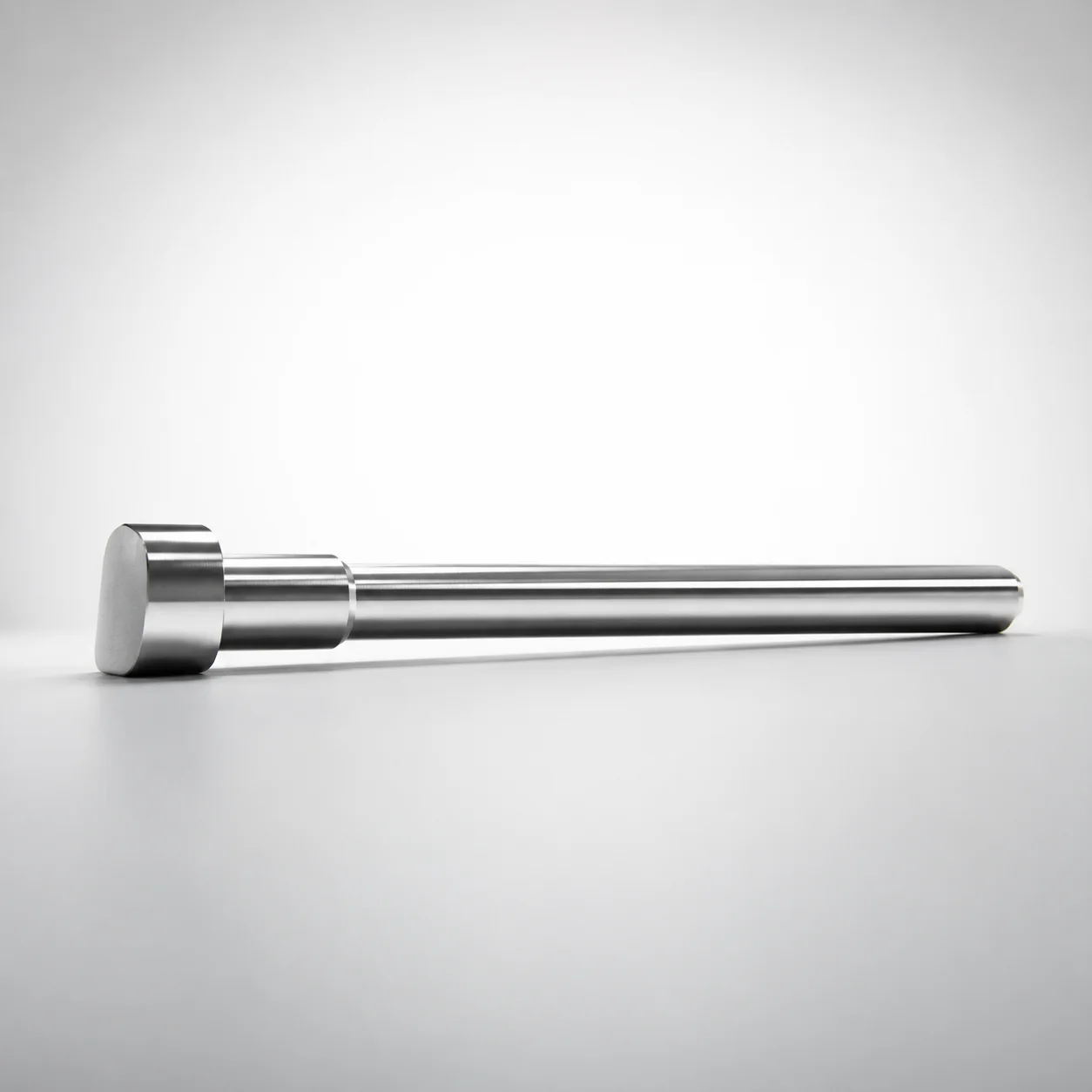
JIS Standard SKH51 Steel D-Shaped Ejector Pins
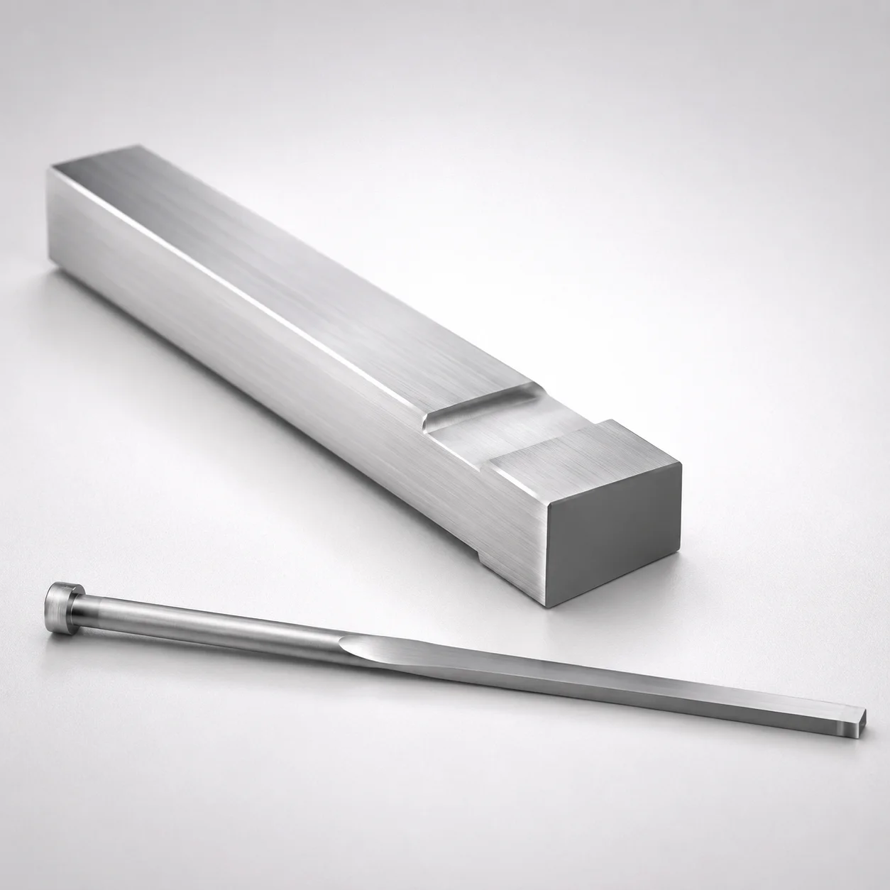
JIS Standard M2 Steel Gas Release Rectangular Ejector Pins
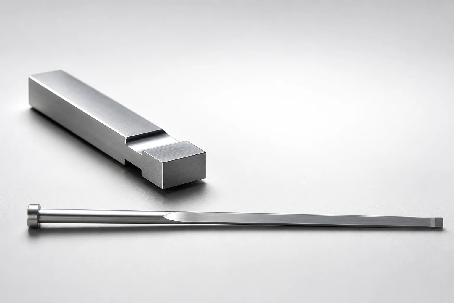
JIS Standard SKH51 Steel Gas Release Rectangular Ejector Pins
Need Custom Specifications?
Our engineering team can help with custom configurations, material selection, and volume pricing.