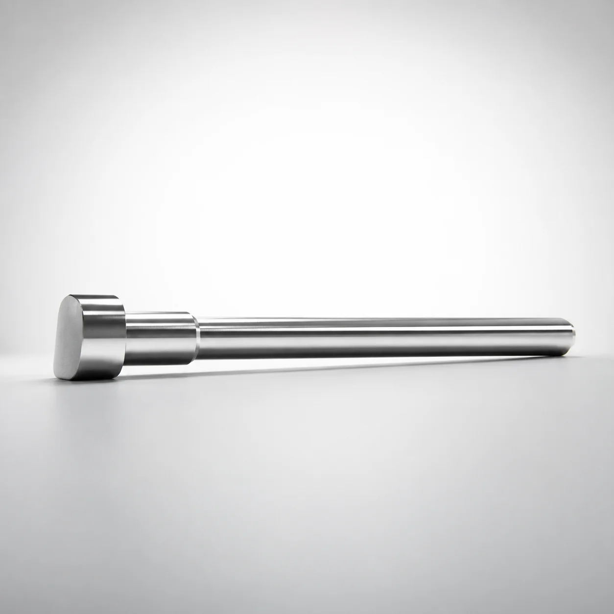
JIS Standard SKH51 Steel D-Shaped Ejector Pins
D-shaped ejector pins (SKH51 steel) are designed to support stable mold ejection with a D-shaped cross section for positive guidance. These pins are manufactured to JIS-standard requirements and suitable for long production runs.
- D-shaped geometry improves alignment and reduces lateral shifting in the mold
- Quenched SKH51 steel with hardened construction for wear resistance
- Tip/shaft tolerance reference supports reliable fit for consistent ejection performance
- Compatible with Normal or Step trimming designs for different mold layouts
Specifications
64 configurations available
| Head Thickness | P (Tip) (mm) | W (Tip) (mm) | D (Shaft Diameter) (mm) | Type | L (L dimension) (mm) | Dimension N (mm) | type |
|---|---|---|---|---|---|---|---|
| 4mm(T4) | 0.6 ~ 1.4 | 0.3 ~ 1.3 | 1.5 | Step | 50 ~ 200 | 30 ~ 180 | - |
| 4mm(T4) | 0.8 ~ 1.9 | 0.4 ~ 1.8 | 2 | Step | 50 ~ 250 | 30 ~ 230 | - |
| 4mm(T4) | 0.8 ~ 2.4 | 0.4 ~ 2.3 | 2.5 | Step | 50 ~ 250 | 30 ~ 230 | - |
| 4mm(T4) | 1 ~ 2.9 | 0.5 ~ 2.8 | 3 | Step | 50 ~ 300 | 30 ~ 280 | - |
| 4mm(T4) | 1.5 ~ 3.4 | 0.75 ~ 3.3 | 3.5 | Step | 50 ~ 300 | 30 ~ 280 | - |
| 4mm(T4) | 2 ~ 3.9 | 1 ~ 3.8 | 4 | Step | 50 ~ 300 | 30 ~ 280 | - |
| 4mm(T4) | 2.5 ~ 4.4 | 1.25 ~ 4.3 | 4.5 | Step | 50 ~ 300 | 30 ~ 280 | - |
| 4mm(T4) | 3 ~ 4.9 | 1.5 ~ 4.8 | 5 | Step | 50 ~ 350 | 30 ~ 340 | - |
| 4mm(T4) | 3.5 ~ 5.4 | 1.75 ~ 5.3 | 5.5 | Step | 50 ~ 350 | 30 ~ 340 | - |
| 4mm(T4) | 4 ~ 5.9 | 2 ~ 5.8 | 6 | Step | 50 ~ 350 | 30 ~ 340 | - |
| 4mm(T4) | 4.5 ~ 6.4 | 2.25 ~ 6.3 | 6.5 | Step | 50 ~ 350 | 30 ~ 340 | - |
| 4mm(T4) | 5 ~ 6.9 | 2.5 ~ 6.8 | 7 | Step | 50 ~ 350 | 30 ~ 340 | - |
| 4mm(T4) | 6 ~ 7.9 | 3 ~ 7.8 | 8 | Step | 50 ~ 350 | 30 ~ 340 | - |
| 4mm(T4) | 6.9 ~ 8.9 | 3.45 ~ 8.8 | 9 | Step | 50 ~ 350 | 30 ~ 330 | - |
| 4mm(T4) | 7.9 ~ 9.9 | 3.95 ~ 9.8 | 10 | Step | 50 ~ 350 | 30 ~ 340 | - |
| 4mm(T4) | 8.9 ~ 11.9 | 4.45 ~ 11.8 | 12 | Step | 50 ~ 350 | 30 ~ 330 | - |
| 4mm(JIS) | 0.6 ~ 1.4 | 0.3 ~ 1.3 | 1.5 | Step | 50 ~ 200 | 30 ~ 180 | - |
| 4mm(JIS) | 0.8 ~ 1.9 | 0.4 ~ 1.8 | 2 | Step | 50 ~ 250 | 30 ~ 180 | - |
| 4mm(JIS) | 0.8 ~ 2.4 | 0.4 ~ 2.3 | 2.5 | Step | 50 ~ 250 | 30 ~ 180 | - |
| 4mm(JIS) | 1 ~ 2.9 | 0.5 ~ 2.8 | 3 | Step | 50 ~ 300 | 30 ~ 180 | - |
| 4mm(JIS) | 1.5 ~ 3.4 | 0.75 ~ 3.3 | 3.5 | Step | 50 ~ 300 | 30 ~ 180 | - |
| 6mm(JIS) | 2 ~ 3.9 | 1 ~ 3.8 | 4 | Step | 50 ~ 300 | 30 ~ 180 | - |
| 6mm(JIS) | 2.5 ~ 4.4 | 1.25 ~ 4.3 | 4.5 | Step | 50 ~ 300 | 30 ~ 180 | - |
| 6mm(JIS) | 3 ~ 4.9 | 1.5 ~ 4.8 | 5 | Step | 50 ~ 350 | 30 ~ 180 | - |
| 6mm(JIS) | 3.5 ~ 5.4 | 1.75 ~ 5.3 | 5.5 | Step | 50 ~ 350 | 30 ~ 180 | - |
| 6mm(JIS) | 4 ~ 5.9 | 2 ~ 5.8 | 6 | Step | 50 ~ 350 | 30 ~ 180 | - |
| 6mm(JIS) | 4.5 ~ 6.4 | 2.25 ~ 6.3 | 6.5 | Step | 50 ~ 350 | 30 ~ 180 | - |
| 6mm(JIS) | 5 ~ 6.9 | 2.5 ~ 6.8 | 7 | Step | 50 ~ 350 | 30 ~ 180 | - |
| 8mm(JIS) | 6 ~ 7.9 | 3 ~ 7.8 | 8 | Step | 50 ~ 350 | 30 ~ 180 | - |
| 8mm(JIS) | 6.9 ~ 8.9 | 3.45 ~ 8.8 | 9 | Step | 50 ~ 350 | 30 ~ 220 | - |
| 8mm(JIS) | 7.9 ~ 9.9 | 3.95 ~ 9.8 | 10 | Step | 50 ~ 350 | 30 ~ 220 | - |
| 8mm(JIS) | 8.9 ~ 11.9 | 4.45 ~ 11.8 | 12 | Step | 50 ~ 350 | 30 ~ 220 | - |
| 4mm(T4) | - | 0.75 ~ 1.4 | 1.5 | Normal | 50 ~ 200 | 30 ~ 180 | - |
| 4mm(T4) | - | 1 ~ 1.9 | 2 | Normal | 50 ~ 250 | 30 ~ 230 | - |
| 4mm(T4) | - | 1.25 ~ 2.4 | 2.5 | Normal | 50 ~ 250 | 30 ~ 230 | - |
| 4mm(T4) | - | 1.5 ~ 2.9 | 3 | Normal | 50 ~ 300 | 30 ~ 280 | - |
| 4mm(T4) | - | 1.75 ~ 3.4 | 3.5 | Normal | 50 ~ 300 | 30 ~ 280 | - |
| 4mm(T4) | - | 2 ~ 3.9 | 4 | Normal | 50 ~ 300 | 30 ~ 280 | - |
| 4mm(T4) | - | 2.25 ~ 4.4 | 4.5 | Normal | 50 ~ 300 | 30 ~ 280 | - |
| 4mm(T4) | - | 2.5 ~ 4.9 | 5 | Normal | 50 ~ 350 | 30 ~ 330 | - |
| 4mm(T4) | - | 2.75 ~ 5.4 | 5.5 | Normal | 50 ~ 350 | 30 ~ 330 | - |
| 4mm(T4) | - | 3 ~ 5.9 | 6 | Normal | 50 ~ 350 | 30 ~ 330 | - |
| 4mm(T4) | - | 3.25 ~ 6.4 | 6.5 | Normal | 50 ~ 350 | 30 ~ 330 | - |
| 4mm(T4) | - | 3.5 ~ 6.9 | 7 | Normal | 50 ~ 350 | 30 ~ 330 | - |
| 4mm(T4) | - | 4 ~ 7.9 | 8 | Normal | 50 ~ 350 | 30 ~ 330 | - |
| 4mm(T4) | - | 4.5 ~ 8.9 | 9 | Normal | 50 ~ 350 | 30 ~ 330 | - |
| 4mm(T4) | - | 5 ~ 9.9 | 10 | Normal | 50 ~ 350 | 30 ~ 330 | - |
| 4mm(T4) | - | 6 ~ 11.9 | 12 | Normal | 50 ~ 350 | 30 ~ 330 | - |
| 4mm(JIS) | - | 0.75 ~ 1.4 | 1.5 | Normal | 50 ~ 200 | 30 ~ 180 | - |
| 4mm(JIS) | - | 1 ~ 1.9 | 2 | Normal | 50 ~ 250 | 30 ~ 230 | - |
Product Guide
Application Scenarios+
D-shaped ejector pins are used in injection mold tooling where stable, guided ejection is critical. The D-shaped cross section provides positive orientation in the ejector plate and bore, helping reduce lateral shifting and improving repeatability across long production cycles.
- Automotive connector and terminal molds: In high-cycle housings and small inserts, the guided geometry supports consistent ejection force transfer, reducing scuffing and maintaining part edge quality.
- Appliance and consumer electronics housings: Pins with the stepped or normal trimming compatibility support different part ejection layouts, helping align ejector systems over varying cavity depths.
- General precision multi-cavity molds: Hardened construction helps resist wear where ejector pins experience frequent sliding contact during core/cavity opening and closing.
This SKH51-based variant is suited to these applications due to its hardened, quenched construction for wear resistance and its JIS-standard dimensional consistency for reliable fit between the pin and the mold’s ejector pin bore.
Material & Process Details+
JIS Standard SKH51 steel is an HSS-type tooling material commonly selected for ejector pins that require good wear resistance and dimensional stability. In practice, SKH51 is widely treated as equivalent to AISI M2 class high-speed steel behavior, offering high hardness after proper heat treatment.
- Heat treatment state: hardened construction produced via quenching and tempering (quenched SKH51) to achieve a durable service hardness for sliding contact.
- Wear resistance vs. toughness: Higher hardness improves resistance to abrasion and pin-bore fretting, while tempered microstructure maintains usable toughness to avoid brittle chipping under repeated ejection loads.
- Process suitability: The steel’s hardenability supports fine finishing and maintains performance under continuous cycling.
Compared with softer tool steels, SKH51 generally prioritizes wear life; compared with fully carbide-heavy solutions, it typically provides better toughness at lower cost and easier machining/finishing for ejector components.
Sizing & Selection Guide+
Select ejector pin dimensions by matching the pin’s shaft diameter (D), tip geometry, and overall length (L) to the ejector plate thickness and the mold’s ejection stroke requirements.
- Shaft diameter (D): choose from 1.5 to 12 mm to fit the pin bore size with the required clearance/fit for your ejector plate design.
- Tip geometry: pick P (tip) = 0.6 to 8.9 mm and W (tip) = 0.3 to 6 mm to match the contact/support area at the ejector interface and ensure stable guidance without over-constraining motion.
- Length (L): available ranges include 50–200, 50–250, 50–300, or 50–350 mm, selected to cover your cavity depth plus the required ejection travel.
- Design type: select Normal or Step depending on whether the mold layout requires a stepped shoulder for trimming or clearance.
Use the provided Dimension N options (30–180 up to 30–340/30–330 depending on variant) to align shoulder position with your ejector plate and guide bushing requirements. For press-fit or tight-running systems, confirm bore tolerance and surface finish to avoid binding.
Frequently Asked Questions
Which SKH51 D-shaped ejector pin size should I choose for a given ejector plate bore diameter?+
How do the tip dimensions P and W affect guidance and ejection stability?+
When should I specify a Step type instead of Normal for D-shaped ejector pins?+
What length L range is typically needed for my mold cavity depth?+
Is SKH51 appropriate for high-wear ejector applications and repeated cycling?+
Related Products
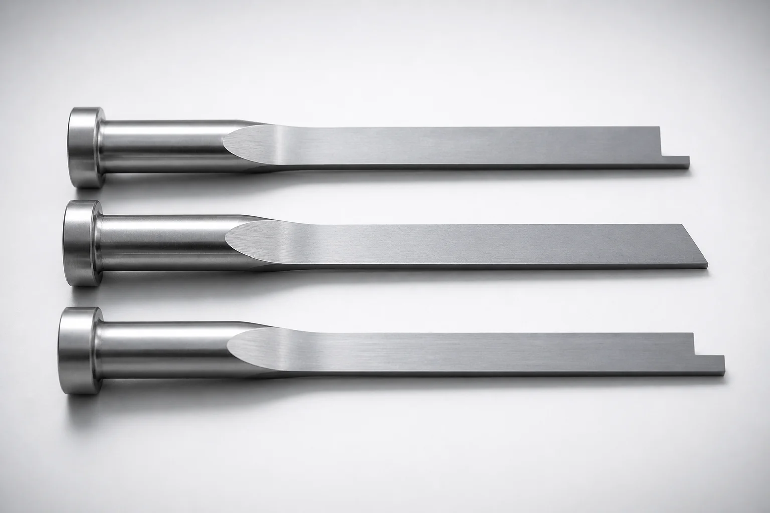
JIS Standard SKH51 Steel Precision Rectangular Ejector Pins with Tip Processed
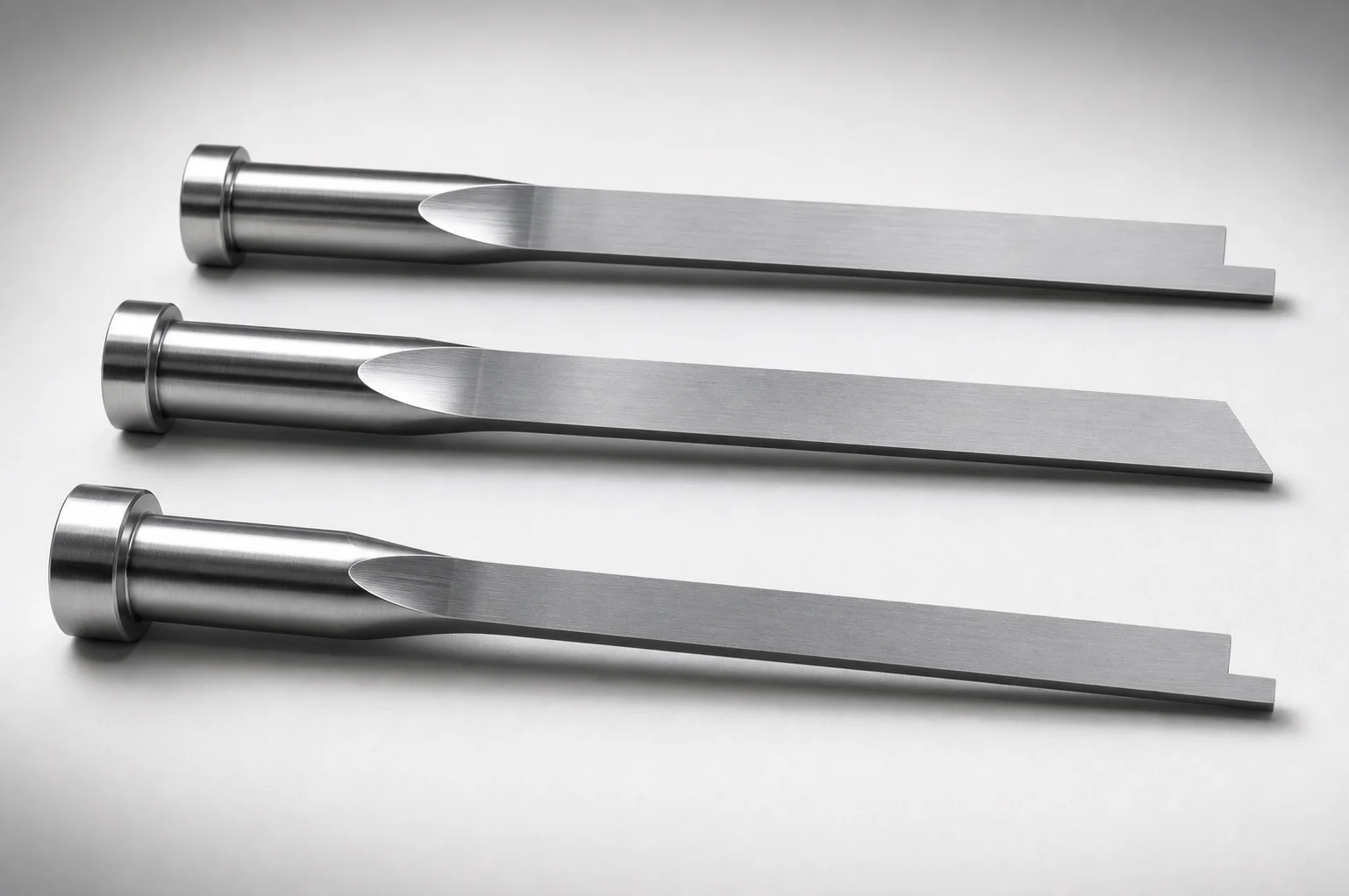
JIS Standard SKH51 Steel Tip-Processed Rectangular Ejector Pins
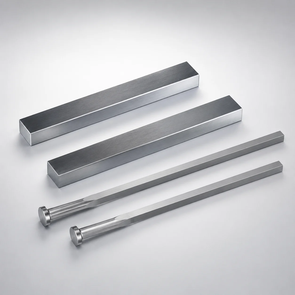
JIS Standard SKH51 Steel Rectangular Ejector Pins with Engraving
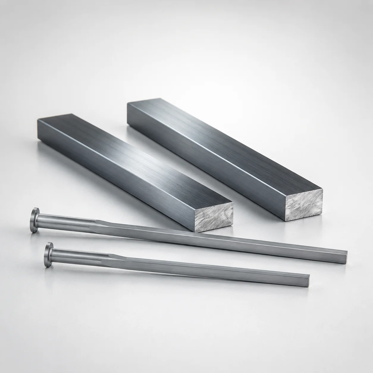
M2 Steel Rectangular Ejector Pins with Engraving - Flat-Head
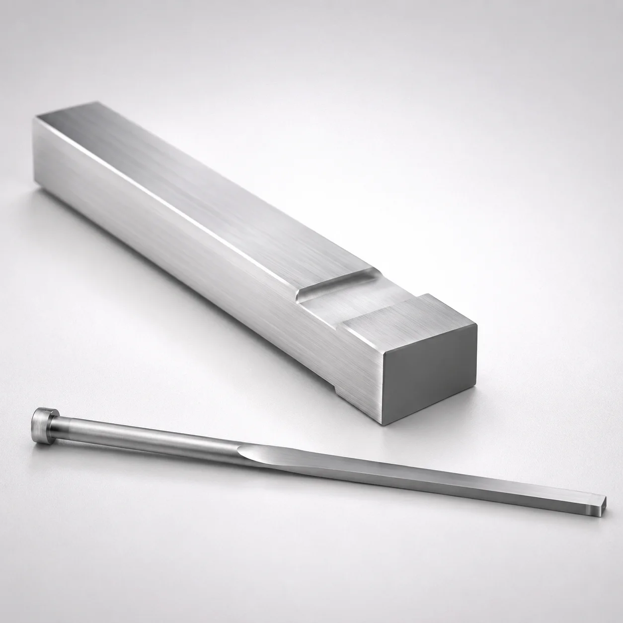
JIS Standard M2 Steel Gas Release Rectangular Ejector Pins
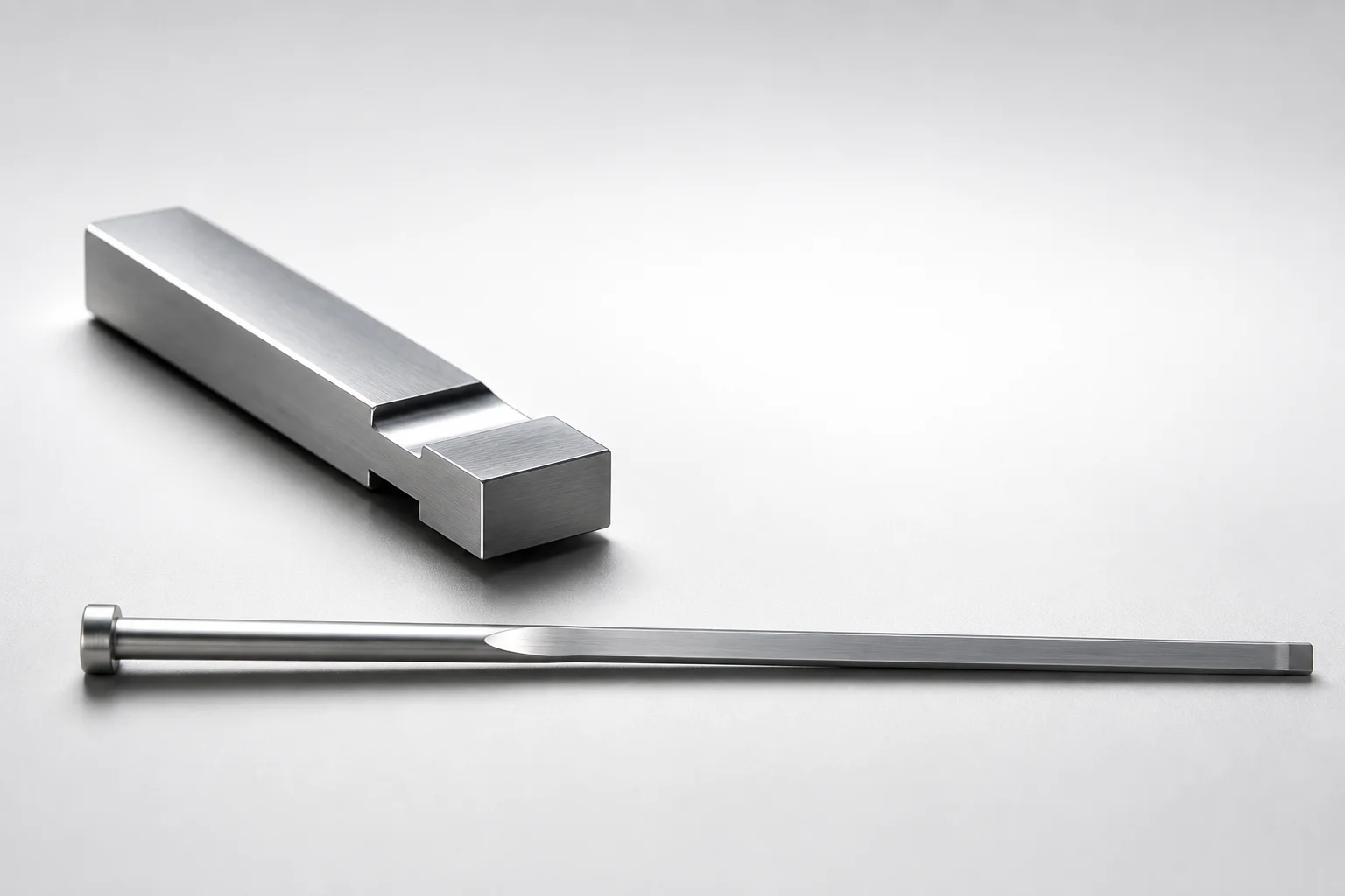
JIS Standard SKH51 Steel Gas Release Rectangular Ejector Pins
Need Custom Specifications?
Our engineering team can help with custom configurations, material selection, and volume pricing.