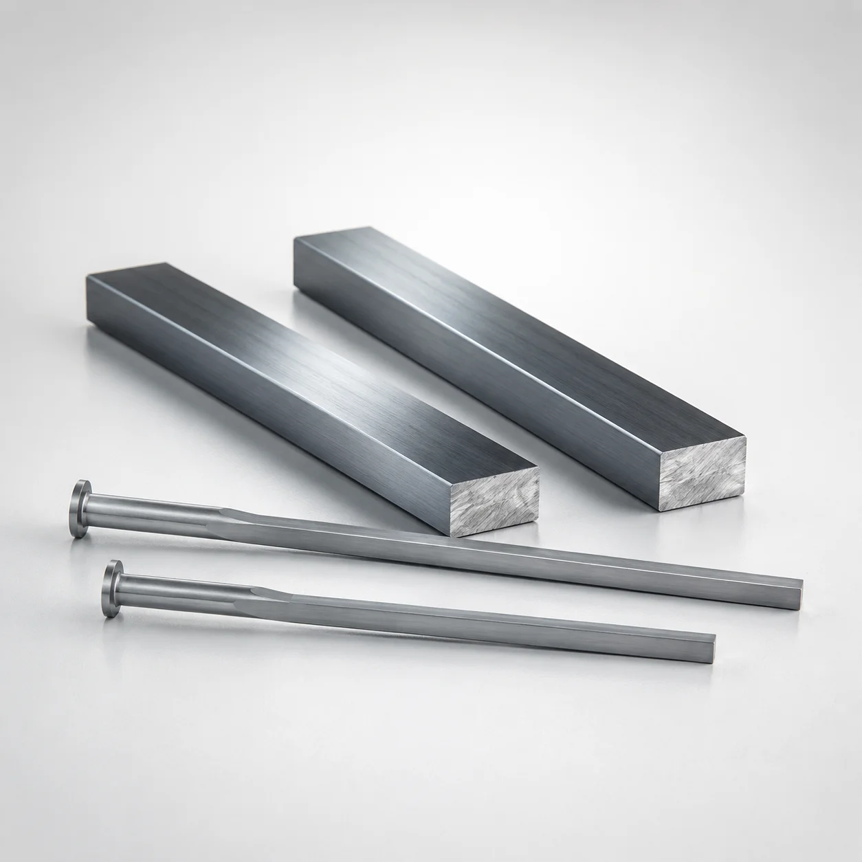
M2 Steel Rectangular Ejector Pins with Engraving - Flat-Head
Rectangular ejector pins with engraving (SKH51 steel) provide repeatable ejection while carrying ※Designation by WOS engraving for clear tool traceability. The T=4 mm flat head supports stable alignment in precision mold assemblies.
- With engraving for part/tool identification, using ※Designation by WOS
- SKH51 steel construction with quenched & hardened tool-steel performance for wear resistance
- Controlled trimming design for consistent pin seating and reliable ejection repeatability
- Typical for die casting and injection mold cores requiring marked ejector components
Specifications
89 configurations available
| P (Tip) (mm) | W (Tip) (mm) | D (Shaft Diameter) (mm) | Character Engraving Type | Number of engraving characters | L (L dimension) (mm) | Dimension N (mm) | Engraving character designation | type |
|---|---|---|---|---|---|---|---|---|
| 0.8 ~ 1.7 | 0.3 ~ 1.6 | 2 | Concave character | 1 characters | 40 ~ 250 | 23 ~ 240 | ※Designation by WOS | - |
| 0.8 ~ 2.2 | 0.3 ~ 2.1 | 2.5 | Concave character | 1 characters | 40 ~ 250 | 26 ~ 240 | ※Designation by WOS | - |
| 1 ~ 2.7 | 0.3 ~ 2.7 | 3 | Concave character | 1 characters | 40 ~ 250 | 27 ~ 240 | ※Designation by WOS | - |
| 1 ~ 3.2 | 0.3 ~ 3.2 | 3.5 | Concave character | 1 characters | 40 ~ 250 | 27 ~ 240 | ※Designation by WOS | - |
| 1 ~ 3.7 | 0.3 ~ 3.7 | 4 | Concave character | 1 characters | 40 ~ 250 | 29 ~ 240 | ※Designation by WOS | - |
| 1.2 ~ 4.2 | 0.3 ~ 4.2 | 4.5 | Concave character | 1 characters | 40 ~ 250 | 29 ~ 240 | ※Designation by WOS | - |
| 1.5 ~ 4.8 | 0.4 ~ 4.66 | 5 | Concave character | 1 characters | 50 ~ 250 | 31 ~ 240 | ※Designation by WOS | - |
| 1.8 ~ 5.3 | 0.4 ~ 5.09 | 5.5 | Concave character | 1 characters | 50 ~ 250 | 31 ~ 240 | ※Designation by WOS | - |
| 2 ~ 5.8 | 0.5 ~ 5.5 | 6 | Concave character | 1 characters | 50 ~ 250 | 33 ~ 240 | ※Designation by WOS | - |
| 2 ~ 6.3 | 0.5 ~ 6.07 | 6.5 | Concave character | 1 characters | 50 ~ 250 | 40 ~ 240 | ※Designation by WOS | - |
| 2.3 ~ 6.8 | 0.5 ~ 6.43 | 7 | Concave character | 1 characters | 50 ~ 250 | 40 ~ 240 | ※Designation by WOS | - |
| 2.3 ~ 7.8 | 0.5 ~ 7.49 | 8 | Concave character | 1 characters | 50 ~ 250 | 40 ~ 240 | ※Designation by WOS | - |
| 2.3 ~ 8.3 | 0.5 ~ 8.07 | 8.5 | Concave character | 1 characters | 50 ~ 250 | 40 ~ 240 | ※Designation by WOS | - |
| 3 ~ 9.8 | 0.5 ~ 9.43 | 10 | Concave character | 1 characters | 50 ~ 250 | 40 ~ 240 | ※Designation by WOS | - |
| 3 ~ 10.3 | 0.5 ~ 9.95 | 10.5 | Concave character | 1 characters | 50 ~ 250 | 40 ~ 240 | ※Designation by WOS | - |
| 0.8 ~ 1.7 | 0.3 ~ 1.7 | 2 | Concave character (Sequential numbering) | 1 characters | 40 ~ 250 | 23 ~ 240 | ※Designation by WOS | - |
| 0.8 ~ 2.2 | 0.3 ~ 2.2 | 2.5 | Concave character (Sequential numbering) | 1 characters | 40 ~ 250 | 26 ~ 240 | ※Designation by WOS | - |
| 1 ~ 2.7 | 0.3 ~ 2.7 | 3 | Concave character (Sequential numbering) | 1 characters | 40 ~ 250 | 27 ~ 240 | ※Designation by WOS | - |
| 1 ~ 3.2 | 0.3 ~ 3.2 | 3.5 | Concave character (Sequential numbering) | 1 characters | 40 ~ 250 | 27 ~ 240 | ※Designation by WOS | - |
| 1 ~ 3.7 | 0.3 ~ 3.7 | 4 | Concave character (Sequential numbering) | 1 characters | 40 ~ 250 | 29 ~ 240 | ※Designation by WOS | - |
| 1.2 ~ 4.2 | 0.3 ~ 4.2 | 4.5 | Concave character (Sequential numbering) | 1 characters | 40 ~ 250 | 29 ~ 240 | ※Designation by WOS | - |
| 1.5 ~ 4.8 | 0.4 ~ 4.8 | 5 | Concave character (Sequential numbering) | 1 characters | 50 ~ 250 | 31 ~ 240 | ※Designation by WOS | - |
| 1.8 ~ 5.3 | 0.4 ~ 5.3 | 5.5 | Concave character (Sequential numbering) | 1 characters | 50 ~ 250 | 31 ~ 240 | ※Designation by WOS | - |
| 2 ~ 5.8 | 0.5 ~ 5.8 | 6 | Concave character (Sequential numbering) | 1 characters | 50 ~ 250 | 33 ~ 240 | ※Designation by WOS | - |
| 2 ~ 6.3 | 0.5 ~ 6.3 | 6.5 | Concave character (Sequential numbering) | 1 characters | 50 ~ 250 | 40 ~ 240 | ※Designation by WOS | - |
| 2.3 ~ 6.8 | 0.5 ~ 6.8 | 7 | Concave character (Sequential numbering) | 1 characters | 50 ~ 250 | 40 ~ 240 | ※Designation by WOS | - |
| 2.3 ~ 7.8 | 0.5 ~ 7.8 | 8 | Concave character (Sequential numbering) | 1 characters | 50 ~ 250 | 40 ~ 240 | ※Designation by WOS | - |
| 2.3 ~ 8.3 | 0.7 ~ 8.07 | 8.5 | Concave character (Sequential numbering) | 1 characters | 50 ~ 250 | 40 ~ 240 | ※Designation by WOS | - |
| 3 ~ 9.8 | 0.5 ~ 9.8 | 10 | Concave character (Sequential numbering) | 1 characters | 50 ~ 250 | 40 ~ 240 | ※Designation by WOS | - |
| 3 ~ 10.3 | 0.7 ~ 9.95 | 10.5 | Concave character (Sequential numbering) | 1 characters | 50 ~ 250 | 40 ~ 240 | ※Designation by WOS | - |
| 0.8 ~ 1.7 | 0.3 ~ 1.6 | 2 | Concave character | 2 characters | 40 ~ 250 | 23 ~ 240 | ※Designation by WOS | - |
| 0.8 ~ 2.2 | 0.3 ~ 2.1 | 2.5 | Concave character | 2 characters | 40 ~ 250 | 26 ~ 240 | ※Designation by WOS | - |
| 1 ~ 2.7 | 0.3 ~ 2.7 | 3 | Concave character | 2 characters | 40 ~ 250 | 27 ~ 240 | ※Designation by WOS | - |
| 1 ~ 3.2 | 0.3 ~ 3.2 | 3.5 | Concave character | 2 characters | 40 ~ 250 | 27 ~ 240 | ※Designation by WOS | - |
| 1 ~ 3.7 | 0.3 ~ 3.7 | 4 | Concave character | 2 characters | 40 ~ 250 | 29 ~ 240 | ※Designation by WOS | - |
| 1.2 ~ 4.2 | 0.3 ~ 4.2 | 4.5 | Concave character | 2 characters | 40 ~ 250 | 29 ~ 240 | ※Designation by WOS | - |
| 1.5 ~ 4.8 | 0.4 ~ 4.66 | 5 | Concave character | 2 characters | 50 ~ 250 | 31 ~ 240 | ※Designation by WOS | - |
| 2.3 ~ 5.3 | 0.4 ~ 5.09 | 5.5 | Concave character | 2 characters | 50 ~ 250 | 31 ~ 240 | ※Designation by WOS | - |
| 2 ~ 5.8 | 0.5 ~ 5.5 | 6 | Concave character | 2 characters | 50 ~ 250 | 33 ~ 240 | ※Designation by WOS | - |
| 2 ~ 6.3 | 0.5 ~ 6.07 | 6.5 | Concave character | 2 characters | 50 ~ 250 | 40 ~ 240 | ※Designation by WOS | - |
| 2.3 ~ 6.8 | 0.5 ~ 6.43 | 7 | Concave character | 2 characters | 50 ~ 250 | 40 ~ 240 | ※Designation by WOS | - |
| 2.3 ~ 7.8 | 0.5 ~ 7.49 | 8 | Concave character | 2 characters | 50 ~ 250 | 40 ~ 240 | ※Designation by WOS | - |
| 2.3 ~ 8.3 | 0.5 ~ 8.07 | 8.5 | Concave character | 2 characters | 50 ~ 250 | 40 ~ 240 | ※Designation by WOS | - |
| 3 ~ 9.8 | 0.5 ~ 9.43 | 10 | Concave character | 2 characters | 50 ~ 250 | 40 ~ 240 | ※Designation by WOS | - |
| 3 ~ 10.3 | 0.5 ~ 9.95 | 10.5 | Concave character | 2 characters | 50 ~ 250 | 40 ~ 240 | ※Designation by WOS | - |
| 1 ~ 2.7 | 0.3 ~ 2.7 | 3 | Concave character (Sequential numbering) | 2 characters | 40 ~ 250 | 27 ~ 240 | ※Designation by WOS | - |
| 1 ~ 3.2 | 0.3 ~ 3.2 | 3.5 | Concave character (Sequential numbering) | 2 characters | 40 ~ 250 | 27 ~ 240 | ※Designation by WOS | - |
| 1 ~ 3.7 | 0.3 ~ 3.7 | 4 | Concave character (Sequential numbering) | 2 characters | 40 ~ 250 | 29 ~ 240 | ※Designation by WOS | - |
| 1.2 ~ 4.2 | 0.3 ~ 4.2 | 4.5 | Concave character (Sequential numbering) | 2 characters | 40 ~ 250 | 29 ~ 240 | ※Designation by WOS | - |
| 1.5 ~ 4.8 | 0.4 ~ 4.8 | 5 | Concave character (Sequential numbering) | 2 characters | 50 ~ 250 | 31 ~ 240 | ※Designation by WOS | - |
Product Guide
Application Scenarios+
These rectangular ejector pins are used in injection mold tooling where reliable part release and traceability of ejector components are required. The engraved designation helps maintain clear tool/work instructions across maintenance cycles.
- Automotive and industrial connector housings: the flat-head configuration with T=4 mm supports stable seating in precision ejector assemblies, helping maintain repeatable ejection under high cycle conditions.
- Die-cast and injection-mold cores with marked tooling: the concave engraving (※Designation by WOS) provides durable identification for rapid inspection, allowing engineers to correlate specific ejector pins to cavity/core sets.
- Multi-cavity molds: controlled trimming supports consistent pin seating so ejection repeatability is maintained across cavities, reducing variation in part release.
Built from SKH51 tool steel, the variant is suited for tooling environments that demand strong wear resistance and dimensional stability during sustained ejector motion.
Material & Process Details+
This product is specified in SKH51 tool steel, commonly aligned to AISI M2 equivalent in function (high-speed steel class). Its quenched & hardened tool-steel condition is intended to deliver high wear resistance at the ejector working surfaces.
- Hardness: the hardened tool-steel state provides durable cutting-edge-style wear performance; hardness is typically selected to balance wear resistance with acceptable toughness for ejector duty.
- Wear resistance vs. toughness: higher hardness improves scuffing and abrasion resistance during repeated ejection, while sufficient toughness is needed to avoid chipping at the pin tip and flat-head contact areas.
- Manufacturing process: steel is quenched and hardened, then typically tempered to stabilize hardness and reduce brittleness for long-run ejector operation.
Compared with lower-alloy case-hardened steels, SKH51 hardened performance is generally better for severe sliding/impact wear, while requiring correct heat-treatment control to maintain toughness.
Sizing & Selection Guide+
Selection starts by matching the ejector pin geometry to the cavity/core ejector layout and the available space for stroke and guidance. Use the provided ranges to engineer fit and seating.
- Shaft diameter (D): choose D = 2 ~ 10.5 mm to match the guide bore and minimize clearance-induced wobble.
- Tip dimensions: select P = 0.8 ~ 3 mm and W = 0.3 ~ 0.7 mm to align with the part-contact area and reduce stress concentration at the release surface.
- Length (L): pick L = 40 ~ 250 mm (or 50 ~ 250 mm as applicable) to achieve the required protrusion and safe engagement depth.
- Dimension N: use N = 23 ~ 40 mm to satisfy the stack-up between ejector plate, support, and any retention features.
The flat head has a T=4 mm thickness, which must fit the ejector assembly step/seat. Engraved character count (1–5) and concave character style are available options, while the ※Designation by WOS wording is fixed.
Frequently Asked Questions
How do I select the correct shaft diameter D (2–10.5 mm) for proper pin guidance in my ejector plate?+
Choose D from 2 ~ 10.5 mm to match your guide bore or bushing size in the ejector system. The correct diameter reduces lateral play that can cause uneven ejection. If your mold design uses close guidance, confirm the clearance tolerance at the guide interface before locking the pin diameter.
What tip dimensions P and W (P=0.8–3 mm, W=0.3–0.7 mm) should be used to minimize part scuffing while ensuring release?+
Use P = 0.8 ~ 3 mm and W = 0.3 ~ 0.7 mm to size the contacting tip geometry to the part’s release surface. Smaller widths can reduce contact area and scuffing risk, while sufficient P is needed to maintain stable contact. Verify that the tip geometry fits the cavity spacing and does not interfere with features around the ejector pin land.
How does the flat-head thickness T=4 mm affect seating and alignment in ejector assemblies?+
The product includes a flat head with T=4 mm, which seats in the ejector plate/support interface. Proper seating helps maintain alignment and supports consistent ejection repeatability. During design, ensure the step height and retention geometry account for the flat-head thickness to avoid rocking or uneven load transfer.
Is the engraving character designation fixed, and how do the selectable engraving counts (1–5) impact tool traceability?+
The engraving text includes a fixed designation: ※Designation by WOS. You can select the number of concave characters as 1, 2, 3, 4, or 5, and the engraving type is concave character (including sequential numbering). This allows you to standardize traceability across multiple ejector pins in multi-cavity or multi-line tooling.
What length range L (40–250 mm or 50–250 mm) and N (23–40 mm) should I confirm for stack-up and safe engagement?+
Confirm L in the allowed range (40 ~ 250 mm, or 50 ~ 250 mm depending on configuration) so the pin achieves the needed protrusion without bottoming. Use N = 23 ~ 40 mm to match the distance in your assembly stack-up (ejector plate/support and retention). Validate the stroke path and engagement depth to prevent interference during full travel.
Related Products
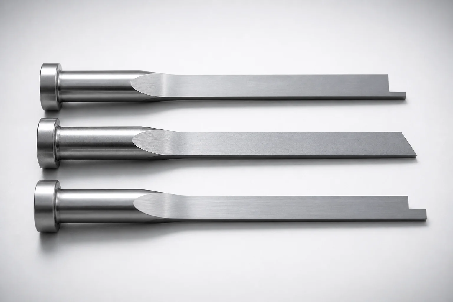
JIS Standard SKH51 Steel Precision Rectangular Ejector Pins with Tip Processed
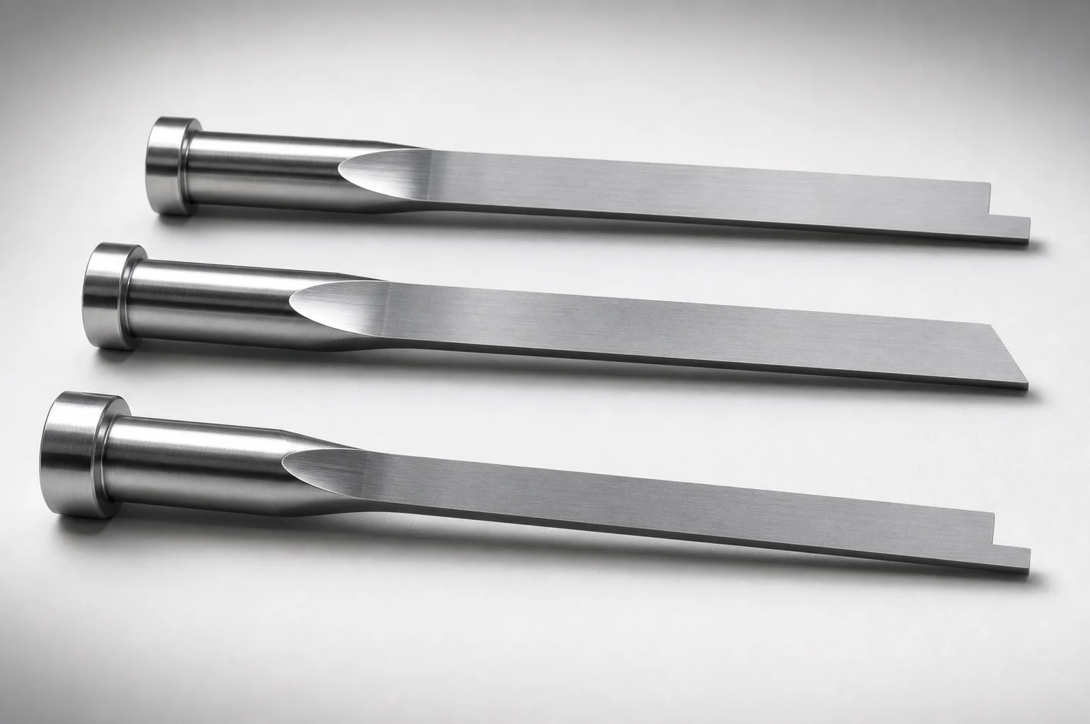
JIS Standard SKH51 Steel Tip-Processed Rectangular Ejector Pins
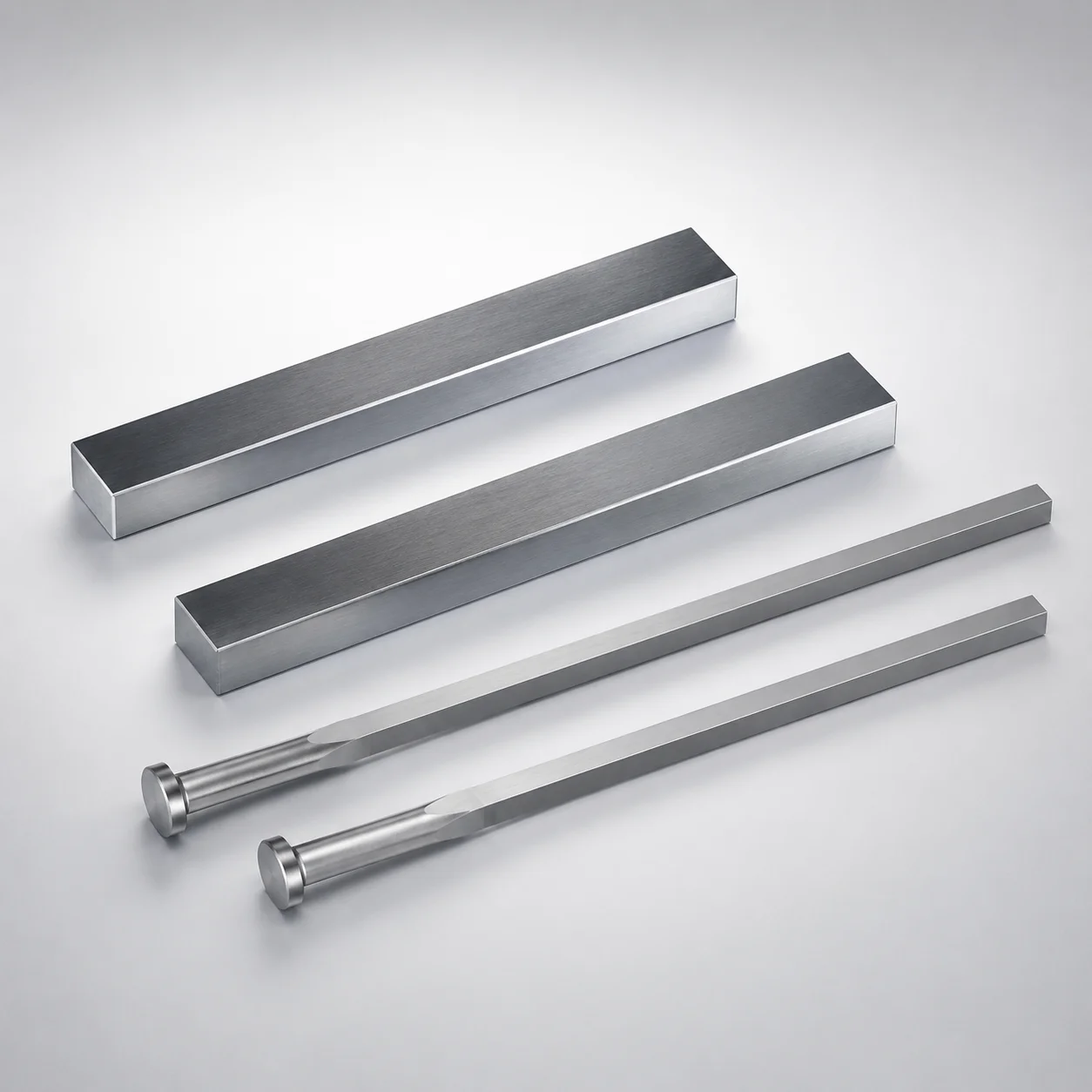
JIS Standard SKH51 Steel Rectangular Ejector Pins with Engraving
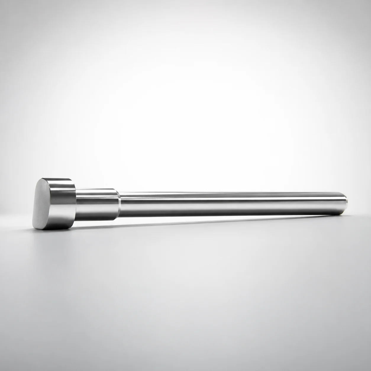
JIS Standard SKH51 Steel D-Shaped Ejector Pins
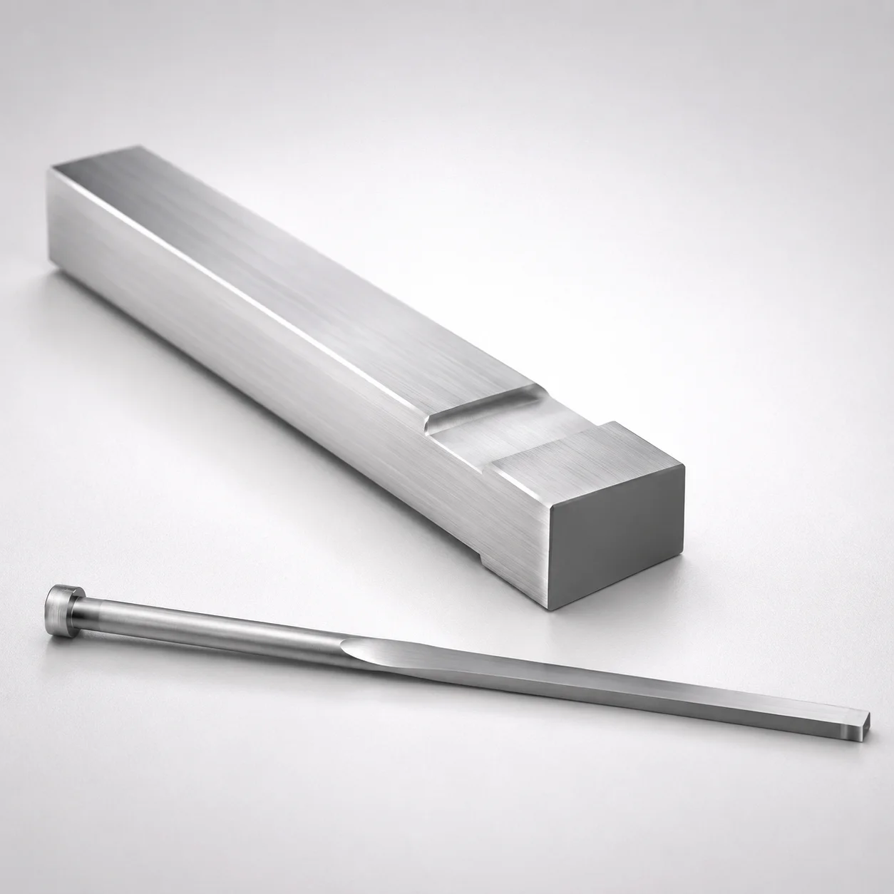
JIS Standard M2 Steel Gas Release Rectangular Ejector Pins
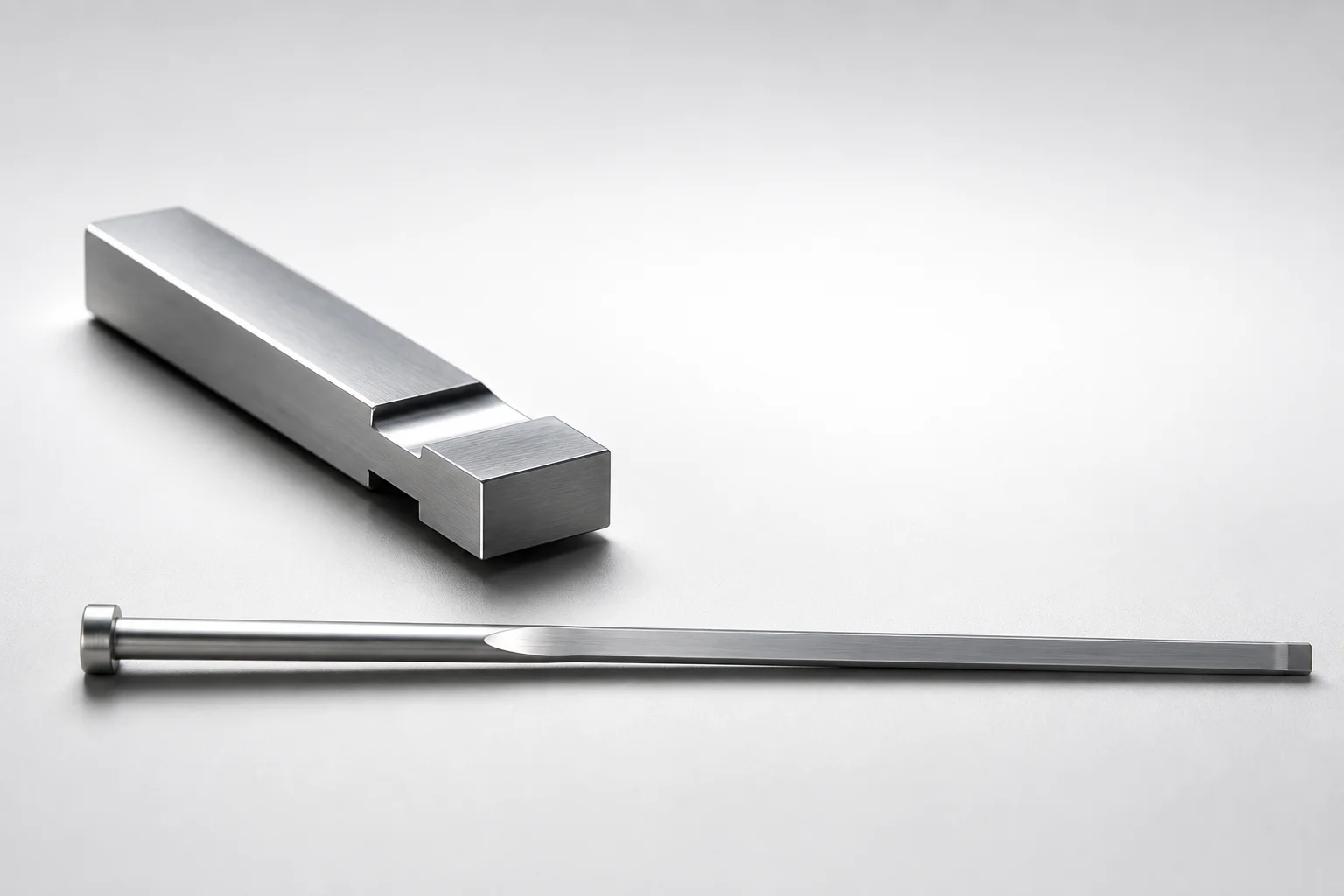
JIS Standard SKH51 Steel Gas Release Rectangular Ejector Pins
Need Custom Specifications?
Our engineering team can help with custom configurations, material selection, and volume pricing.