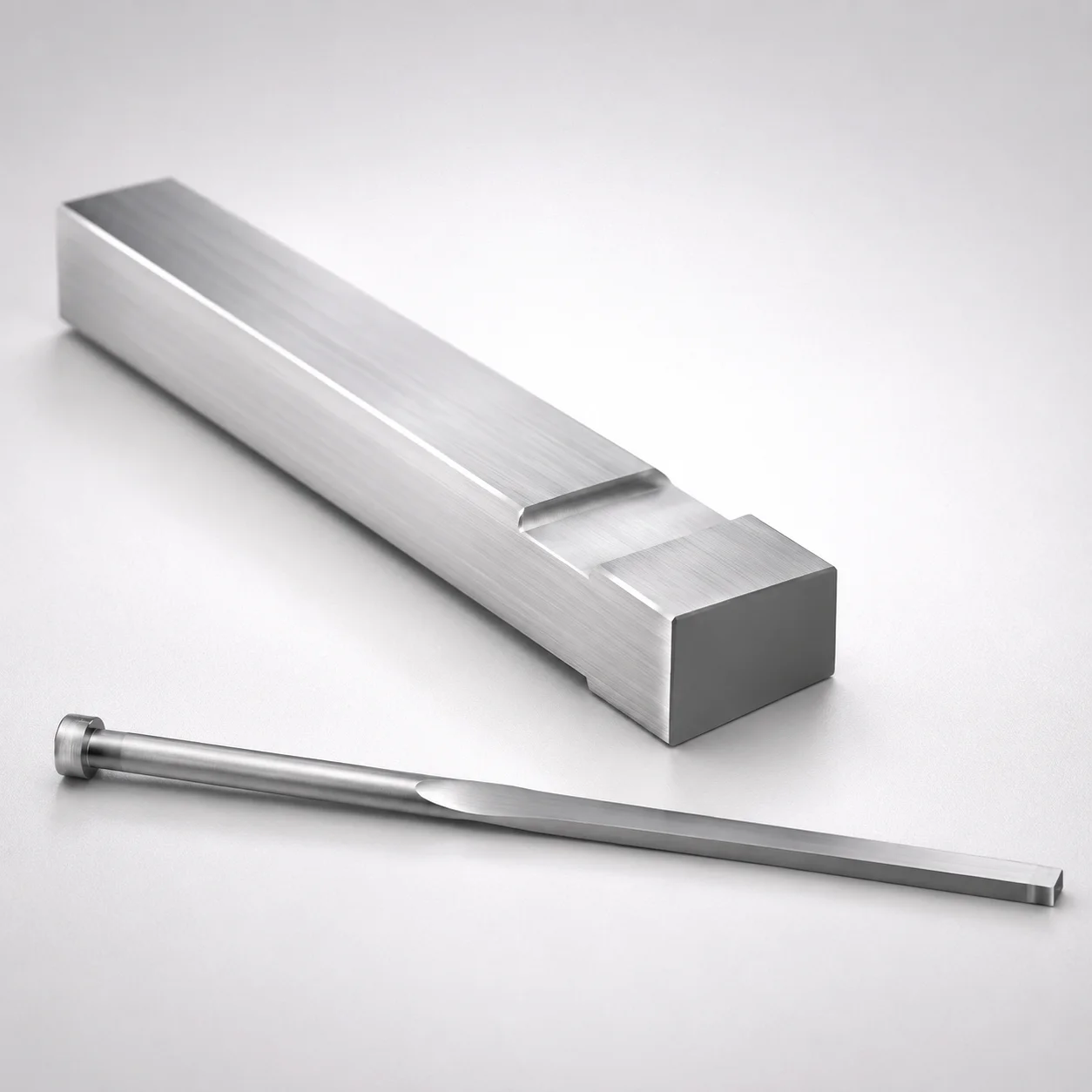
JIS Standard M2 Steel Gas Release Rectangular Ejector Pins
Gas release rectangular ejector pins (M2 steel) are engineered with a built-in gas vent to support efficient mold exhaust and steady ejection performance. Rectangular geometry helps maintain consistent positioning under high cycle loads.
- Gas release shape with integrated gas vent to improve exhaust during molding
- M2 steel construction provides durable wear resistance for long service in production molds
- Supports tight tip fit using 0/-0.01 tolerance reference for controlled assembly
- JIS-standard manufacturing for compatibility with typical mold components and tooling layouts
Specifications
30 configurations available
| Head Thickness | P (Tip) (mm) | W (Tip) (mm) | D (Shaft Diameter) (mm) | L (L dimension) (mm) | Dimension N (mm) | type |
|---|---|---|---|---|---|---|
| 4mm(T4) | 1 ~ 1.3 | 1 ~ 1.3 | 1.5 | 40 ~ 250 | 23 ~ 250 | - |
| 4mm(T4) | 1 ~ 1.8 | 1 ~ 1.8 | 2 | 40 ~ 300 | 23 ~ 250 | - |
| 4mm(T4) | 1 ~ 2.3 | 1 ~ 2.3 | 2.5 | 40 ~ 300 | 26 ~ 250 | - |
| 4mm(T4) | 1 ~ 2.8 | 1 ~ 2.8 | 3 | 40 ~ 300 | 27 ~ 250 | - |
| 4mm(T4) | 1 ~ 3.3 | 1 ~ 3.3 | 3.5 | 40 ~ 300 | 27 ~ 250 | - |
| 4mm(T4) | 1 ~ 3.8 | 1 ~ 3.8 | 4 | 40 ~ 300 | 29 ~ 250 | - |
| 4mm(T4) | 1.2 ~ 4.3 | 1 ~ 4.3 | 4.5 | 40 ~ 300 | 29 ~ 250 | - |
| 4mm(T4) | 1.5 ~ 4.8 | 1 ~ 4.8 | 5 | 50 ~ 300 | 31 ~ 250 | - |
| 4mm(T4) | 2 ~ 5.3 | 1 ~ 5.3 | 5.5 | 50 ~ 300 | 31 ~ 250 | - |
| 4mm(T4) | 2 ~ 5.8 | 1 ~ 5.8 | 6 | 50 ~ 300 | 33 ~ 250 | - |
| 4mm(T4) | 2 ~ 6.3 | 1 ~ 6.3 | 6.5 | 50 ~ 300 | 40 ~ 250 | - |
| 4mm(T4) | 2.3 ~ 6.8 | 1 ~ 6.8 | 7 | 50 ~ 300 | 40 ~ 250 | - |
| 4mm(T4) | 2.3 ~ 7.8 | 1 ~ 7.8 | 8 | 50 ~ 300 | 40 ~ 250 | - |
| 4mm(T4) | 3 ~ 9.8 | 1 ~ 9.8 | 10 | 50 ~ 300 | 40 ~ 250 | - |
| 4mm(JIS) | 1 ~ 1.3 | 1 ~ 1.3 | 1.5 | 40 ~ 250 | 23 ~ 250 | - |
| 4mm(JIS) | 1 ~ 1.8 | 1 ~ 1.8 | 2 | 40 ~ 300 | 23 ~ 250 | - |
| 4mm(JIS) | 1 ~ 2.3 | 1 ~ 2.3 | 2.5 | 40 ~ 300 | 26 ~ 250 | - |
| 4mm(JIS) | 1 ~ 2.8 | 1 ~ 2.8 | 3 | 40 ~ 300 | 27 ~ 250 | - |
| 4mm(JIS) | 1 ~ 3.3 | 1 ~ 3.3 | 3.5 | 40 ~ 300 | 27 ~ 250 | - |
| 6mm(JIS) | 1 ~ 3.8 | 1 ~ 3.8 | 4 | 40 ~ 350 | 29 ~ 250 | - |
| 6mm(JIS) | 1.2 ~ 4.3 | 1 ~ 4.3 | 4.5 | 40 ~ 350 | 29 ~ 250 | - |
| 6mm(JIS) | 1.5 ~ 4.8 | 1 ~ 4.8 | 5 | 50 ~ 350 | 31 ~ 250 | - |
| 6mm(JIS) | 2 ~ 5.3 | 1 ~ 5.3 | 5.5 | 50 ~ 350 | 31 ~ 250 | - |
| 6mm(JIS) | 2 ~ 5.8 | 1 ~ 5.8 | 6 | 50 ~ 350 | 33 ~ 250 | - |
| 6mm(JIS) | 2 ~ 6.3 | 1 ~ 6.3 | 6.5 | 50 ~ 350 | 40 ~ 250 | - |
| 6mm(JIS) | 2.3 ~ 6.8 | 1 ~ 6.8 | 7 | 50 ~ 350 | 40 ~ 250 | - |
| 8mm(JIS) | 2.3 ~ 7.8 | 1 ~ 7.8 | 8 | 50 ~ 350 | 40 ~ 250 | - |
| 8mm(JIS) | 3 ~ 9.8 | 1 ~ 9.8 | 10 | 50 ~ 350 | 40 ~ 250 | - |
| 8mm(JIS) | 3.5 ~ 11.8 | 1 ~ 11.8 | 12 | 50 ~ 350 | 40 ~ 250 | - |
| 8mm(JIS) | 3.5 ~ 14.8 | 1 ~ 14.8 | 15 | 50 ~ 350 | 40 ~ 250 | - |
Product Guide
Application Scenarios+
This gas-release rectangular ejector pin variant is used in injection mold tooling where stable ejection and consistent exhaust are required. The built-in gas vent supports efficient venting at the pin tip area, helping reduce trapped air and improving part-to-ejector repeatability during high-cycle production.
- Automotive connector and small housing molds: Rectangular guidance helps maintain consistent positioning under repeated cycle loads, while the vented design promotes reliable exhaust for fine-feature releases.
- Appliance and consumer electronics casings: For molds with multiple ejection points, the gas vent helps stabilize ejection accuracy by minimizing pressure buildup around the ejector interface.
- General industrial plastic components: JIS-standard manufacturing supports compatibility with typical tooling layouts and reduces integration effort when pairing with standard ejector systems.
Its M2 steel construction further suits long production runs where ejector wear and dimensional stability are critical.
Material & Process Details+
This ejector pin series is made from JIS Standard M2 tool steel. M2 corresponds closely to the AISI M2 family, commonly selected for balanced hardness and wear resistance in cutting and forming-related tools, and also for durable ejector components.
- Heat treatment (typical for M2 ejector usage): quench-and-temper to achieve a hard working surface suitable for sliding contacts and repeated ejection loads.
- Hardness & performance trade-off: M2 is chosen to provide high wear resistance; increasing hardness improves tip wear life but can reduce toughness if over-hardened.
- Manufacturing approach: bar stock machining into rectangular geometry, followed by heat treatment to develop the required surface hardness.
If you need higher toughness at the expense of some wear resistance, alternative tool steels may be considered, but this series is specifically aligned with M2’s wear-focused properties.
Sizing & Selection Guide+
Select dimensions by matching the ejector pin’s shaft and guided tip geometry to the mold’s ejector plate openings and the cavity/core contact requirements. Start with D (shaft diameter) = 1.5 ~ 15 mm and ensure the opening/fit in the ejector system matches the required guidance and return stability.
- Tip geometry: Choose P (tip) = 1 ~ 3.5 mm and W (tip) = 1 ~ 1 mm to achieve the intended tip contact area and vent effectiveness.
- Length: Use L = 40 ~ 250 / 40 ~ 300 / 50 ~ 300 / 40 ~ 350 / 50 ~ 350 mm to span from the ejector plate to the cavity side without excessive unsupported length.
- Head thickness: Verify T4 or JIS head thickness options = 4 mm (T4), 4/6/8 mm (JIS) to align with ejector plate and spacer stack-up.
- Dimension N: Confirm N = 23 ~ 40 mm for correct step positioning and assembly height.
For controlled assembly and tip seating, reference the provided tolerance guidance of 0/-0.01 where applicable to your pin-to-mold interface.
Frequently Asked Questions
How do the gas vent design and rectangular geometry affect ejector performance during molding?+
The built-in gas vent improves exhaust near the ejector interface, which helps reduce trapped air and supports more repeatable ejection behavior. The rectangular geometry provides guidance that helps maintain consistent positioning under high cycle loads.
What range of shaft diameters (D) are available for integration into ejector plate openings?+
This series covers D (shaft diameter) = 1.5 ~ 15 mm. When selecting, match the ejector plate opening and guidance requirements to maintain stability during cycling and to support accurate tip engagement.
Which length (L) and head thickness (T4/JIS) should be chosen to control assembly height and support?+
Choose L from the available sets: 40 ~ 250, 40 ~ 300, 50 ~ 300, 40 ~ 350, or 50 ~ 350 mm based on your stack-up and cavity-side reach. Confirm head thickness options of 4 mm (T4) or 4/6/8 mm (JIS) so the pin seats correctly against the ejector assembly.
What tip dimensions (P and W) are available, and how do they relate to vent effectiveness and contact area?+
The tip parameters are P = 1 ~ 3.5 mm and W = 1 ~ 1 mm. Select P to tune the tip contact profile and selecting the correct W ensures the pin tip geometry aligns with the cavity/core interface while retaining the vented exhaust function.
What tolerance reference is provided for controlled assembly of the ejector pin tip?+
The product description references a controlled tip fit using 0/-0.01 tolerance reference. Use this as a sizing/fit guide when specifying the corresponding mold opening or seating feature to achieve consistent assembly and positioning.
Related Products
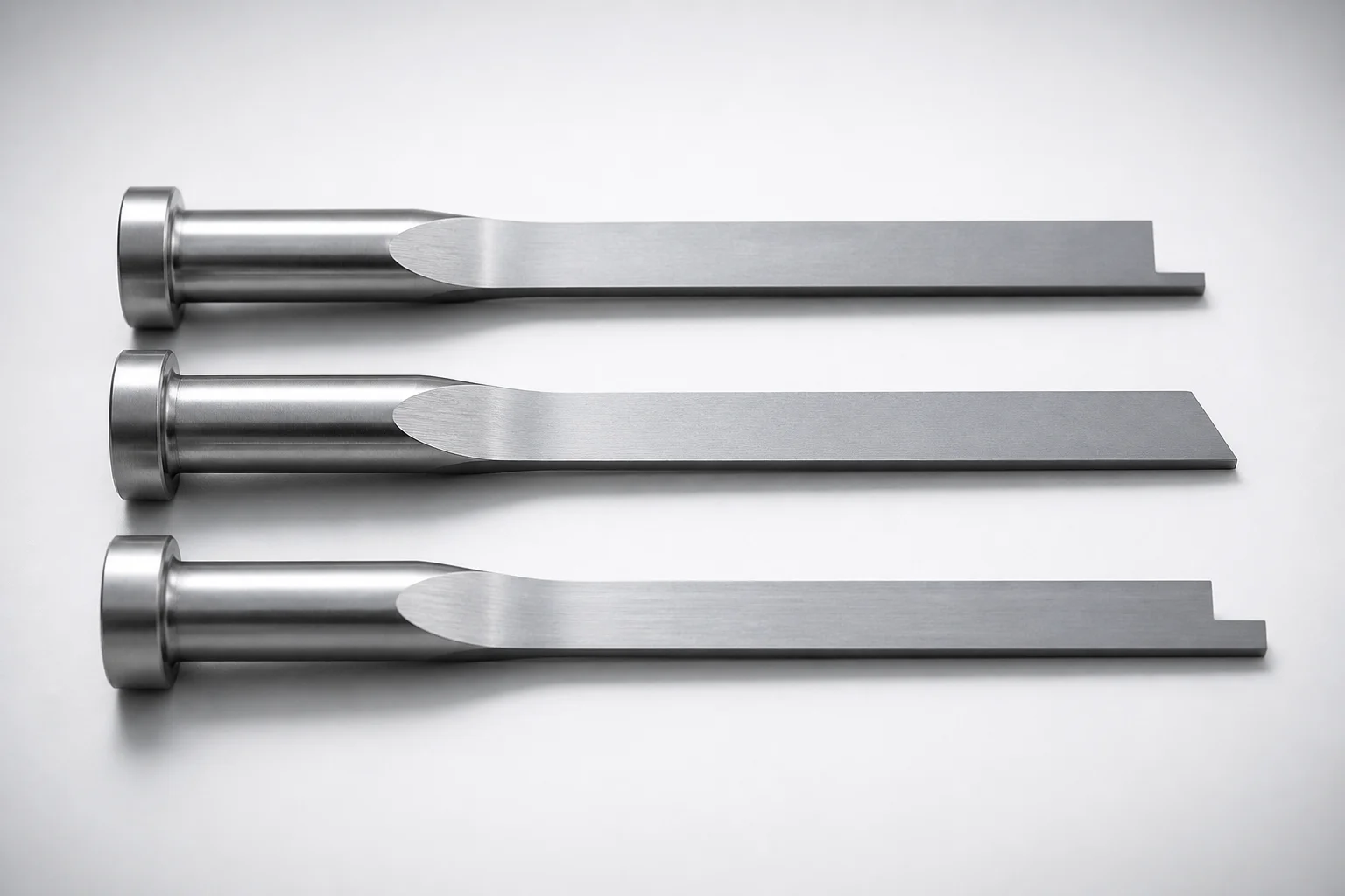
JIS Standard SKH51 Steel Precision Rectangular Ejector Pins with Tip Processed
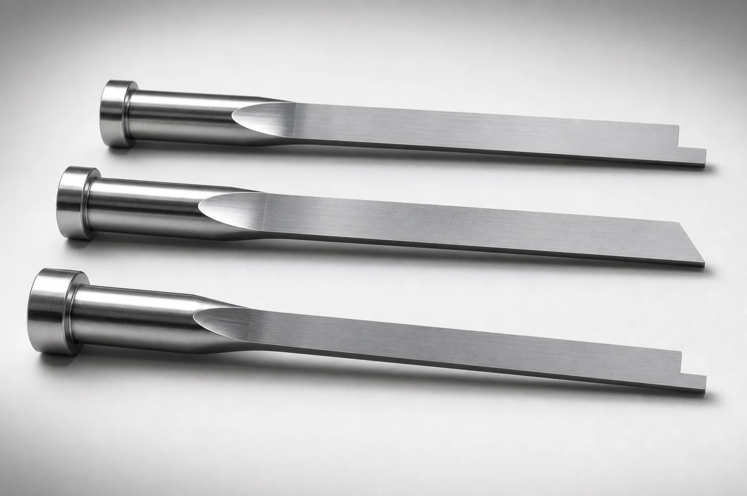
JIS Standard SKH51 Steel Tip-Processed Rectangular Ejector Pins
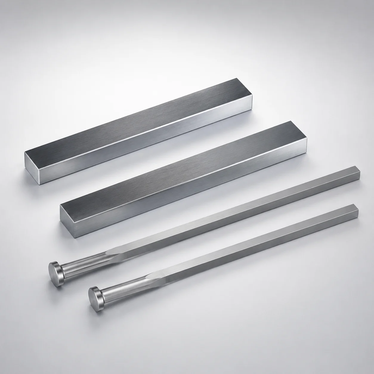
JIS Standard SKH51 Steel Rectangular Ejector Pins with Engraving
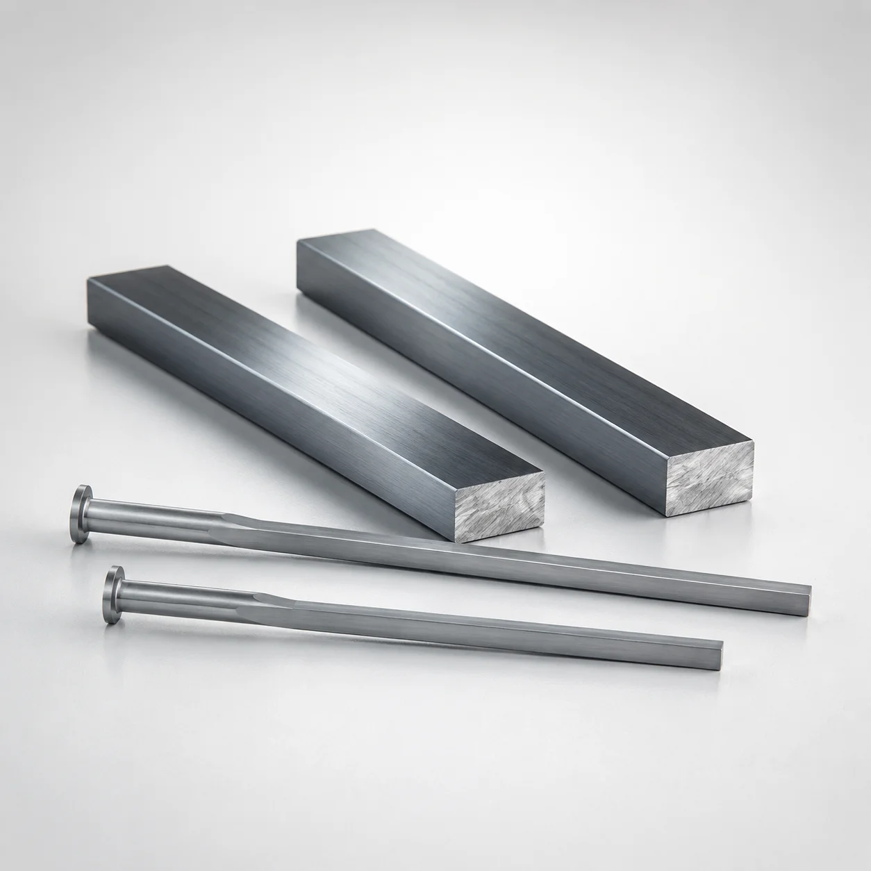
M2 Steel Rectangular Ejector Pins with Engraving - Flat-Head
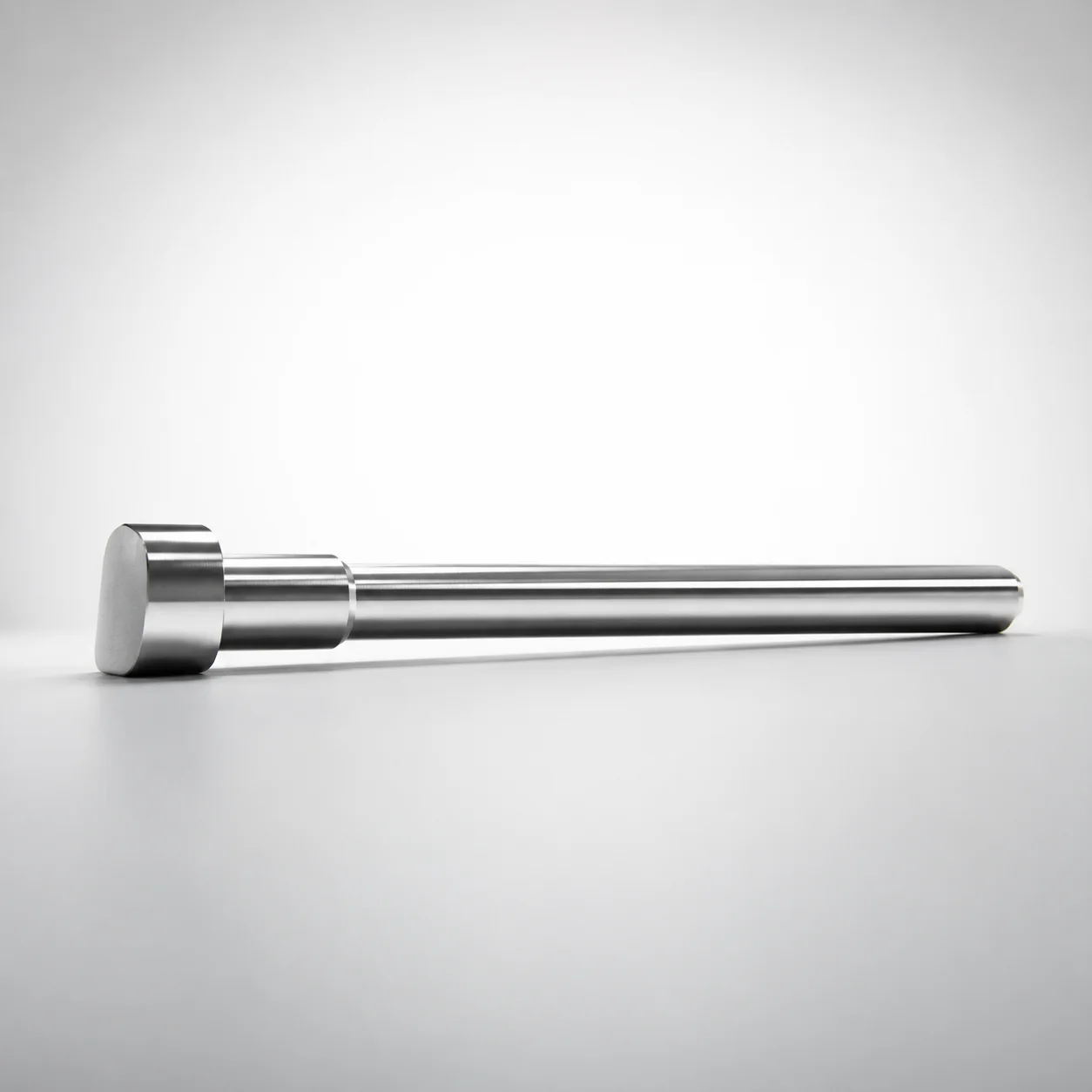
JIS Standard SKH51 Steel D-Shaped Ejector Pins
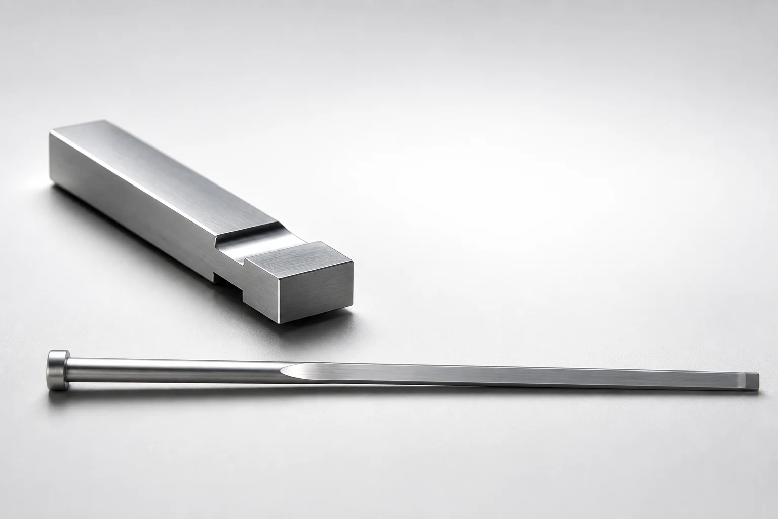
JIS Standard SKH51 Steel Gas Release Rectangular Ejector Pins
Need Custom Specifications?
Our engineering team can help with custom configurations, material selection, and volume pricing.