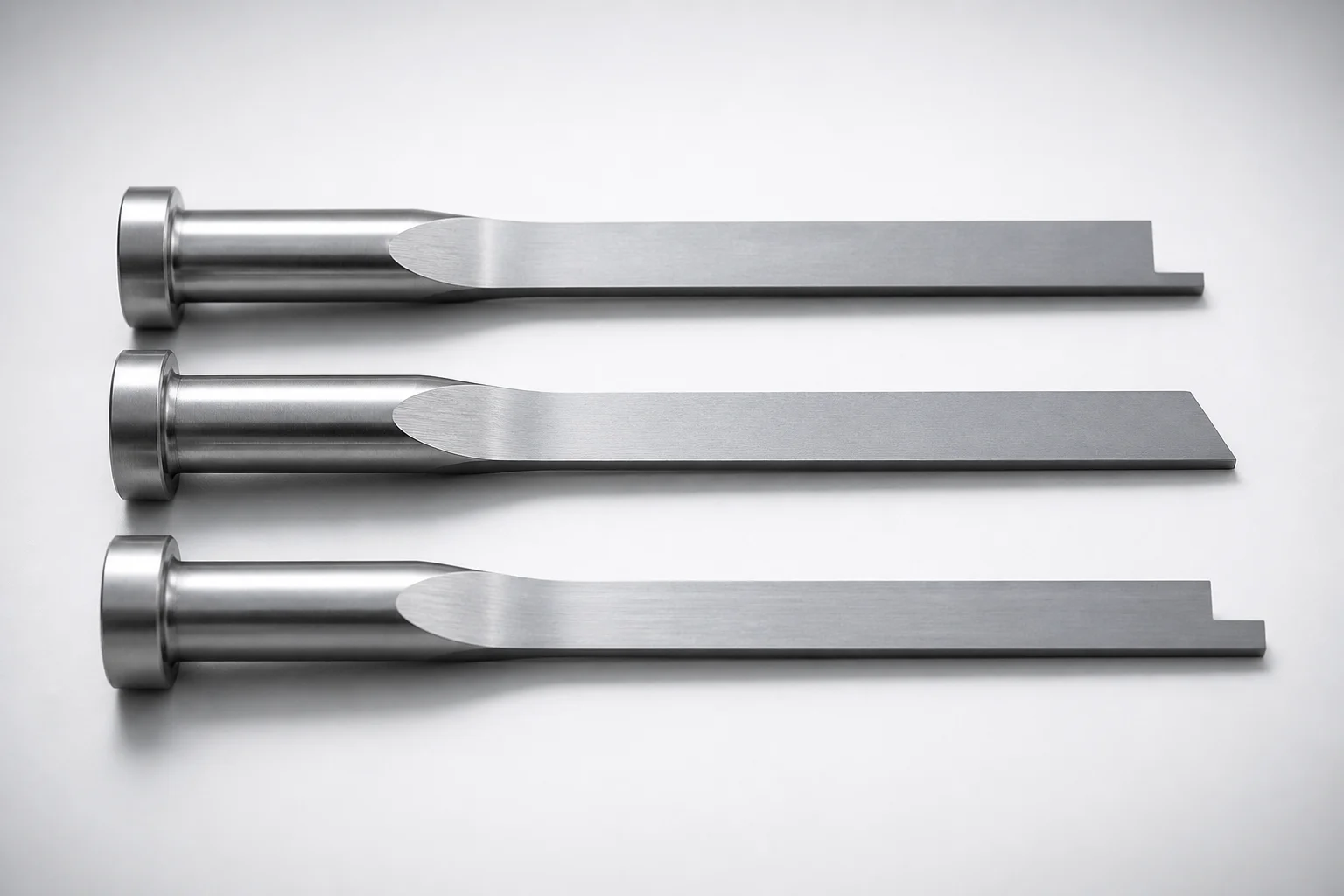
JIS Standard SKH51 Steel Precision Rectangular Ejector Pins with Tip Processed
Precision rectangular ejector pins with tip processed (SKH51 steel) are designed for reliable ejection in precision mold assemblies. The tip-processed end supports consistent contact and improved positioning during operation.
- Tip processing with normal trimming for controlled ejector tip engagement
- SKH51 steel construction with quenched hardening improves wear resistance
- P/W dimension tolerance reference up to 0/-0.005 supports stable fit
- JIS compliant rectangular ejector pin style for standard precision mold use
Specifications
378 configurations available
| Head Thickness | P (Tip) (mm) | W (Tip) (mm) | D (Shaft Diameter) (mm) | Tip Shape | L (L dimension) (mm) | Dimension N (mm) | A (mm) | Dimension C (mm) | G (°) | Dimension R (mm) | Dimension V (mm) | type |
|---|---|---|---|---|---|---|---|---|---|---|---|---|
| 4mm(T4) | 0.8 ~ 1.8 | 0.6 ~ 1.72 | 1.5 | 1X | 50 ~ 250 | 33 ~ 230 | - | - | 1 ~ 45 | - | - | - |
| 4mm(T4) | 0.8 ~ 1.8 | 0.6 ~ 1.72 | 2 | 1X | 50 ~ 250 | 33 ~ 230 | - | - | 1 ~ 45 | - | - | - |
| 4mm(T4) | 0.8 ~ 2.3 | 0.6 ~ 2.26 | 2.5 | 1X | 50 ~ 250 | 33 ~ 230 | - | - | 1 ~ 45 | - | - | - |
| 4mm(T4) | 0.8 ~ 2.8 | 0.6 ~ 2.8 | 3 | 1X | 50 ~ 300 | 33 ~ 250 | - | - | 1 ~ 45 | - | - | - |
| 4mm(T4) | 1 ~ 3.3 | 0.6 ~ 3.3 | 3.5 | 1X | 50 ~ 300 | 33 ~ 250 | - | - | 1 ~ 45 | - | - | - |
| 4mm(T4) | 1 ~ 3.8 | 0.6 ~ 3.8 | 4 | 1X | 50 ~ 300 | 33 ~ 250 | - | - | 1 ~ 45 | - | - | - |
| 4mm(T4) | 1.2 ~ 4.3 | 0.6 ~ 4.3 | 4.5 | 1X | 50 ~ 300 | 33 ~ 250 | - | - | 1 ~ 45 | - | - | - |
| 4mm(T4) | 1.5 ~ 4.8 | 0.6 ~ 4.8 | 5 | 1X | 50 ~ 300 | 33 ��� 250 | - | - | 1 ~ 45 | - | - | - |
| 4mm(T4) | 1.5 ~ 5.3 | 0.8 ~ 5.3 | 5.5 | 1X | 50 ~ 300 | 33 ~ 250 | - | - | 1 ~ 45 | - | - | - |
| 4mm(T4) | 2 ~ 5.8 | 0.8 ~ 5.8 | 6 | 1X | 50 ~ 300 | 33 ~ 250 | - | - | 1 ~ 45 | - | - | - |
| 4mm(T4) | 2 ~ 6.3 | 0.8 ~ 6.3 | 6.5 | 1X | 50 ~ 300 | 40 ~ 250 | - | - | 1 ~ 45 | - | - | - |
| 4mm(T4) | 2.3 ~ 6.8 | 0.8 ~ 6.8 | 7 | 1X | 50 ~ 300 | 40 ~ 250 | - | - | 1 ~ 45 | - | - | - |
| 4mm(T4) | 2.3 ~ 7.8 | 0.8 ~ 7.8 | 8 | 1X | 50 ~ 300 | 40 ~ 250 | - | - | 1 ~ 45 | - | - | - |
| 4mm(T4) | 3 ~ 9.8 | 0.8 ~ 9.8 | 10 | 1X | 50 ~ 300 | 40 ~ 250 | - | - | 1 ~ 45 | - | - | - |
| 4mm(T4) | 0.8 ~ 1.8 | 0.6 ~ 1.72 | 1.5 | 1Y | 50 ~ 250 | 33 ~ 230 | - | - | 1 ~ 45 | - | - | - |
| 4mm(T4) | 0.8 ~ 1.8 | 0.6 ~ 1.72 | 2 | 1Y | 50 ~ 250 | 33 ~ 230 | - | - | 1 ~ 45 | - | - | - |
| 4mm(T4) | 0.8 ~ 2.3 | 0.6 ~ 2.26 | 2.5 | 1Y | 50 ~ 250 | 33 ~ 230 | - | - | 1 ~ 45 | - | - | - |
| 4mm(T4) | 0.8 ~ 2.8 | 0.6 ~ 2.8 | 3 | 1Y | 50 ~ 300 | 33 ~ 250 | - | - | 1 ~ 45 | - | - | - |
| 4mm(T4) | 1 ~ 3.3 | 0.6 ~ 3.3 | 3.5 | 1Y | 50 ~ 300 | 33 ~ 250 | - | - | 1 ~ 45 | - | - | - |
| 4mm(T4) | 1 ~ 3.8 | 0.6 ~ 3.8 | 4 | 1Y | 50 ~ 300 | 33 ~ 250 | - | - | 1 ~ 45 | - | - | - |
| 4mm(T4) | 1.2 ~ 4.3 | 0.6 ~ 4.3 | 4.5 | 1Y | 50 ~ 300 | 33 ~ 250 | - | - | 1 ~ 45 | - | - | - |
| 4mm(T4) | 1.5 ~ 4.8 | 0.6 ~ 4.8 | 5 | 1Y | 50 ~ 300 | 33 ~ 250 | - | - | 1 ~ 45 | - | - | - |
| 4mm(T4) | 1.5 ~ 5.3 | 0.8 ~ 5.3 | 5.5 | 1Y | 50 ~ 300 | 33 ~ 250 | - | - | 1 ~ 45 | - | - | - |
| 4mm(T4) | 2 ~ 5.8 | 0.8 ~ 5.8 | 6 | 1Y | 50 ~ 300 | 33 ~ 250 | - | - | 1 ~ 45 | - | - | - |
| 4mm(T4) | 2 ~ 6.3 | 0.8 ~ 6.3 | 6.5 | 1Y | 50 ~ 300 | 40 ~ 250 | - | - | 1 ~ 45 | - | - | - |
| 4mm(T4) | 2.3 ~ 6.8 | 0.8 ~ 6.8 | 7 | 1Y | 50 ~ 300 | 40 ~ 250 | - | - | 1 ~ 45 | - | - | - |
| 4mm(T4) | 2.3 ~ 7.8 | 0.8 ~ 7.8 | 8 | 1Y | 50 ~ 300 | 40 ~ 250 | - | - | 1 ~ 45 | - | - | - |
| 4mm(T4) | 3 ~ 9.8 | 0.8 ~ 9.8 | 10 | 1Y | 50 ~ 300 | 40 ~ 250 | - | - | 1 ~ 45 | - | - | - |
| 4mm(T4) | 0.8 ~ 1.8 | 0.6 ~ 1.72 | 1.5 | 2X | 50 ~ 250 | 33 ~ 230 | - | - | 45 ~ 90 | - | 0.3 ~ 1.79 | - |
| 4mm(T4) | 0.8 ~ 1.8 | 0.6 ~ 1.72 | 2 | 2X | 50 ~ 250 | 33 ~ 230 | - | - | 45 ~ 90 | - | 0.3 ~ 1.79 | - |
| 4mm(T4) | 0.8 ~ 2.3 | 0.6 ~ 2.26 | 2.5 | 2X | 50 ~ 250 | 33 ~ 230 | - | - | 45 ~ 90 | - | 0.3 ~ 2.29 | - |
| 4mm(T4) | 1 ~ 2.8 | 0.6 ~ 2.72 | 3 | 2X | 50 ~ 300 | 33 ~ 250 | - | - | 45 ~ 90 | - | 0.3 ~ 2.79 | - |
| 4mm(T4) | 1 ~ 3.3 | 0.6 ~ 3.24 | 3.5 | 2X | 50 ~ 300 | 33 ~ 250 | - | - | 45 ~ 90 | - | 0.3 ~ 3.29 | - |
| 4mm(T4) | 1 ~ 3.8 | 0.6 ~ 3.76 | 4 | 2X | 50 ~ 300 | 33 ~ 250 | - | - | 45 ~ 90 | - | 0.3 ~ 3.79 | - |
| 4mm(T4) | 1.2 ~ 4.3 | 0.6 ~ 4.23 | 4.5 | 2X | 50 ~ 300 | 33 ~ 250 | - | - | 45 ~ 90 | - | 0.3 ~ 4.29 | - |
| 4mm(T4) | 1.5 ~ 4.8 | 0.6 ~ 4.66 | 5 | 2X | 50 ~ 300 | 33 ~ 250 | - | - | 45 ~ 90 | - | 0.3 ~ 4.79 | - |
| 4mm(T4) | 1.8 ~ 5.3 | 0.8 ~ 5.09 | 5.5 | 2X | 50 ~ 300 | 33 ~ 250 | - | - | 45 ~ 90 | - | 0.3 ~ 5.29 | - |
| 4mm(T4) | 2 ~ 5.8 | 0.8 ~ 5.55 | 6 | 2X | 50 ~ 300 | 33 ~ 250 | - | - | 45 ~ 90 | - | 0.3 ~ 5.79 | - |
| 4mm(T4) | 2 ~ 6.3 | 0.8 ~ 6.07 | 6.5 | 2X | 50 ~ 300 | 40 ~ 250 | - | - | 45 ~ 90 | - | 0.3 ~ 6.29 | - |
| 4mm(T4) | 2.3 ~ 6.8 | 0.8 ~ 6.5 | 7 | 2X | 50 ~ 300 | 40 ~ 250 | - | - | 45 ~ 90 | - | 0.3 ~ 6.79 | - |
| 4mm(T4) | 2.3 ~ 7.8 | 0.8 ~ 7.55 | 8 | 2X | 50 ~ 300 | 40 ~ 250 | - | - | 45 ~ 90 | - | 0.3 ~ 7.79 | - |
| 4mm(T4) | 3 ~ 9.8 | 0.8 ~ 9.43 | 10 | 2X | 50 ~ 300 | 40 ~ 250 | - | - | 45 ~ 90 | - | 0.3 ~ 9.79 | - |
| 4mm(T4) | 0.8 ~ 1.8 | 0.6 ~ 1.72 | 1.5 | 2Y | 50 ~ 250 | 33 ~ 230 | - | - | 45 ~ 90 | - | 0.3 ~ 1.71 | - |
| 4mm(T4) | 0.8 ~ 1.8 | 0.6 ~ 1.72 | 2 | 2Y | 50 ~ 250 | 33 ~ 230 | - | - | 45 ~ 90 | - | 0.3 ~ 1.71 | - |
| 4mm(T4) | 0.8 ~ 2.3 | 0.6 ~ 2.26 | 2.5 | 2Y | 50 ~ 250 | 33 ~ 230 | - | - | 45 ~ 90 | - | 0.3 ~ 2.25 | - |
| 4mm(T4) | 1 ~ 2.8 | 0.6 ~ 2.72 | 3 | 2Y | 50 ~ 300 | 33 ~ 250 | - | - | 45 ~ 90 | - | 0.3 ~ 2.71 | - |
| 4mm(T4) | 1 ~ 3.3 | 0.6 ~ 3.24 | 3.5 | 2Y | 50 ~ 300 | 33 ~ 250 | - | - | 45 ~ 90 | - | 0.3 ~ 3.23 | - |
| 4mm(T4) | 1 ~ 3.8 | 0.6 ~ 3.76 | 4 | 2Y | 50 ~ 300 | 33 ~ 250 | - | - | 45 ~ 90 | - | 0.3 ~ 3.75 | - |
| 4mm(T4) | 1.2 ~ 4.3 | 0.6 ~ 4.23 | 4.5 | 2Y | 50 ~ 300 | 33 ~ 250 | - | - | 45 ~ 90 | - | 0.3 ~ 4.22 | - |
| 4mm(T4) | 1.5 ~ 4.8 | 0.6 ~ 4.66 | 5 | 2Y | 50 ~ 300 | 33 ~ 250 | - | - | 45 ~ 90 | - | 0.3 ~ 4.65 | - |
Product Guide
Application Scenarios+
These precision rectangular ejector pins are used in injection molds where stable ejection force transfer and repeatable contact at the ejector tip are critical. The tip-processed end promotes consistent engagement with the molded part while reducing the risk of uneven wear and positioning drift during cycling.
Common scenarios include automotive connector and sensor housing molds, where tight knockout tolerances help prevent surface marking and maintain dimensional consistency across high-volume runs. The SKH51 (JIS) construction supports wear resistance at the ejector interface, while the rectangular geometry aids controlled alignment in the ejector plate system.
They are also suitable for precision consumer appliance components and electronics housings that require gentle, controlled ejection. The normal trimming for controlled tip engagement helps maintain reliable part separation, especially where the ejector layout depends on repeatable tip shape and size.
- Tip-processed contact: controlled engagement for stable ejection
- SKH51 steel variant: quenched hardening for improved wear resistance
- Rectangular style: supports alignment in precision ejector assemblies
Material & Process Details+
JIS Standard SKH51 steel is the primary material for this ejector pin variant. In tooling practice, SKH51 is typically selected for high wear resistance in precision components; its quenched hardening state provides a harder surface that resists abrasive and adhesive wear at the ejector tip.
For engineers balancing wear vs. toughness, the quenched-hardening approach increases resistance against tip rounding and scuffing, which is important when the tip repeatedly contacts the molded part or a local ejector interface. However, higher hardness can reduce impact toughness compared with more ductile steels.
- Heat treatment state: quenched hardening (as specified in the product description)
- Hardness: not specified in the provided data (confirm based on the receiving inspection certificate)
- Wear resistance vs. toughness trade-off: harder surface improves service life under frequent contact
If you compare alternatives (e.g., less wear-focused steels), SKH51’s hardness-focused selection is generally preferred where ejector tip wear is a limiting factor in precision molds.
Sizing & Selection Guide+
To select the correct dimensions, start by matching the D (shaft diameter) 1.5–10 mm to the ejector guide bore or receiving gage area in your mold base. Choose the head thickness (T4/JIS) options: 4 mm, 6 mm (JIS), or 8 mm (JIS) based on your ejector plate and stripper thickness stack-up.
Then set the tip geometry for the part contact requirement: P (Tip) 0.8–3 mm, W (Tip) 0.6–0.8 mm, and Tip shape 1–7. These parameters control the local engagement area and affect both ejection stability and wear behavior.
- Length (L) 50–250 mm (or 50–300 mm): confirm projection range for your core/cavity knockout stroke
- Dimension N 33–40 mm, A 0–0.3 mm: match the positional relationship to your ejector plate and guide system
- C 0.5–5 mm (or 0.3–5 mm): verify clearance/step features in the mold design
The product description references P/W dimension tolerance up to 0/-0.005, so plan fits by accounting for the minimum effective tip sizes and the required clearance at the ejector interface.
Frequently Asked Questions
Which SKH51 hardness state is used for these ejector pins, and how does it affect wear at the tip?+
How should I choose between the available head thickness options (4 mm, 6 mm, 8 mm)?+
What are the key tip dimensions I must match to prevent misalignment during ejection?+
How do I select the shaft diameter and length for compatibility with my mold’s guide and knockout travel?+
What does the “tip processed / normal trimming” feature imply for ejector design and wear?+
Related Products
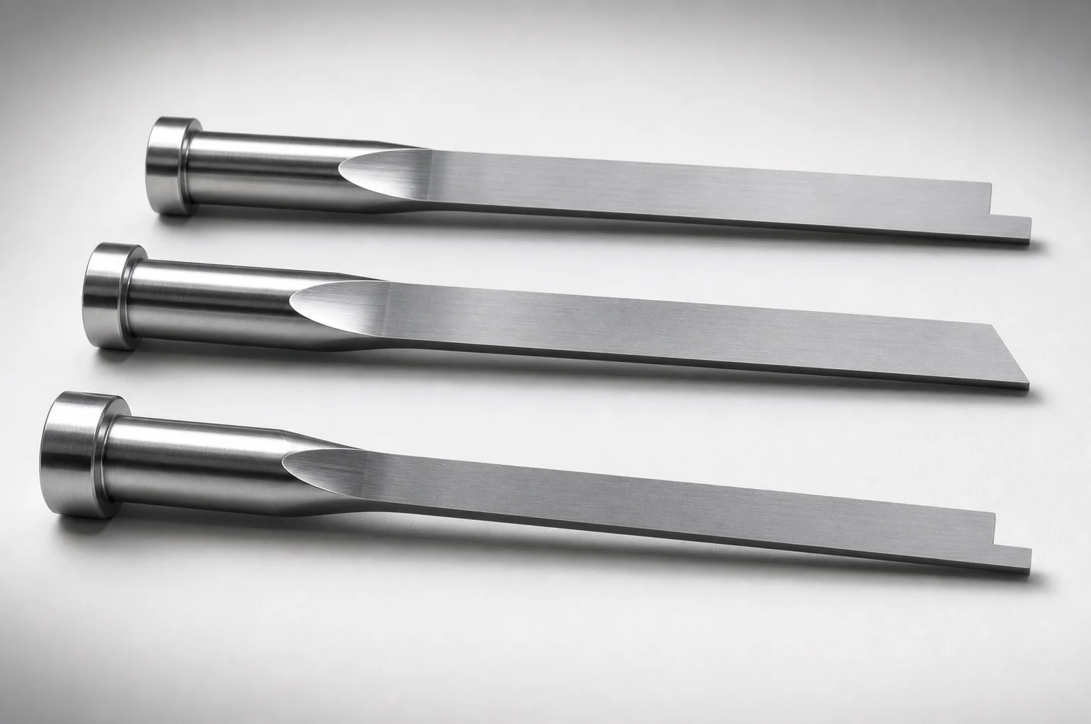
JIS Standard SKH51 Steel Tip-Processed Rectangular Ejector Pins
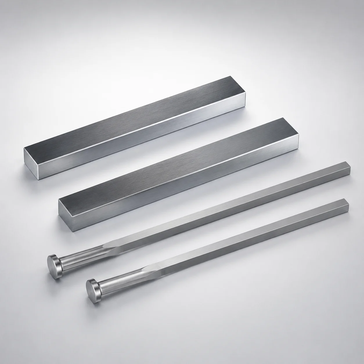
JIS Standard SKH51 Steel Rectangular Ejector Pins with Engraving
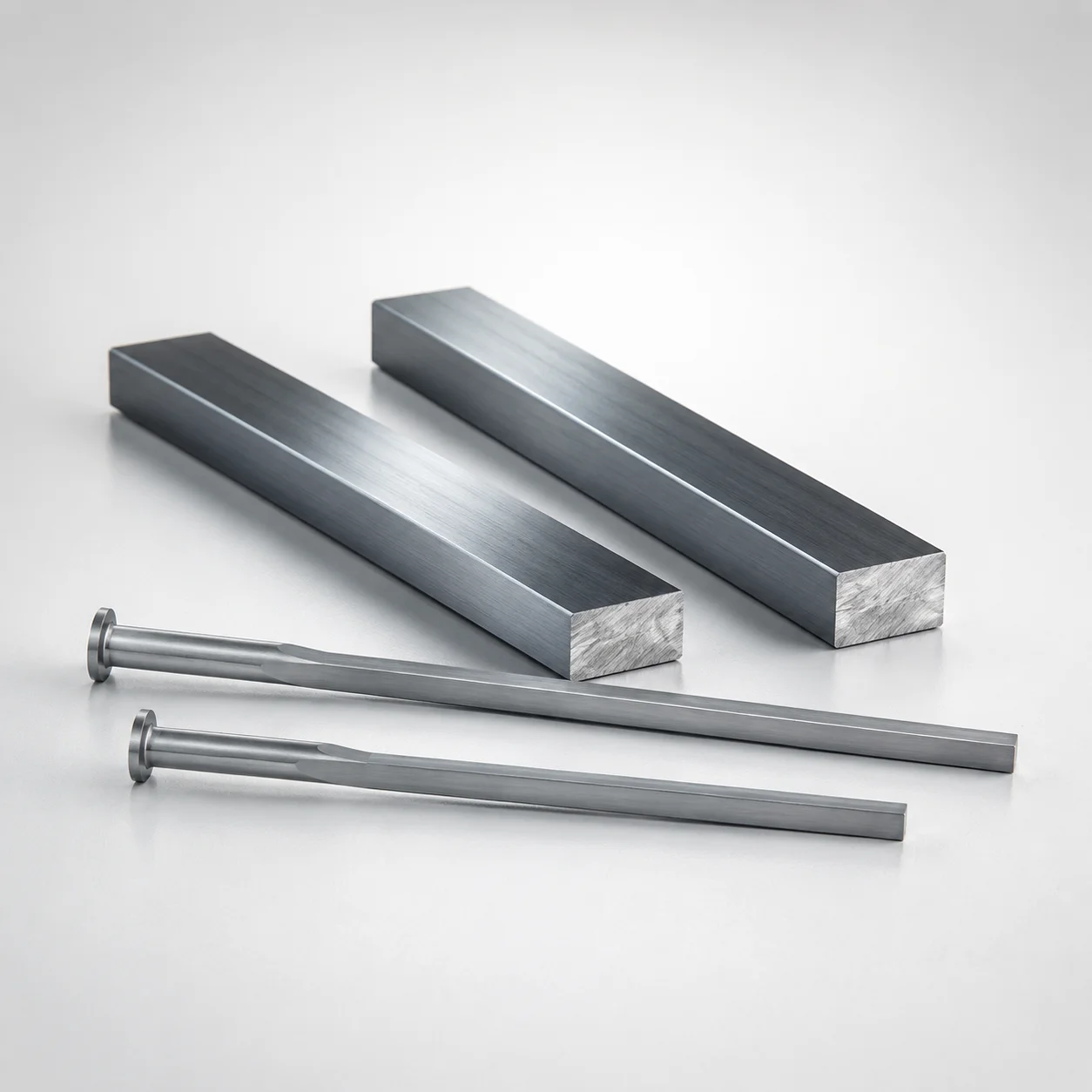
M2 Steel Rectangular Ejector Pins with Engraving - Flat-Head
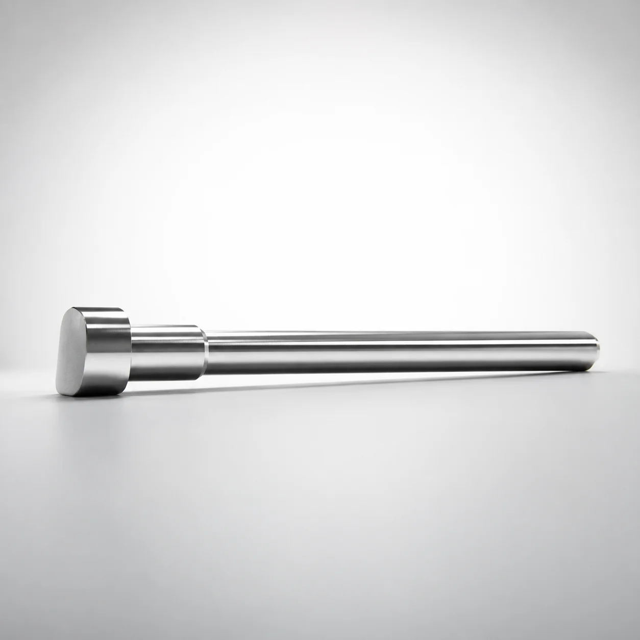
JIS Standard SKH51 Steel D-Shaped Ejector Pins
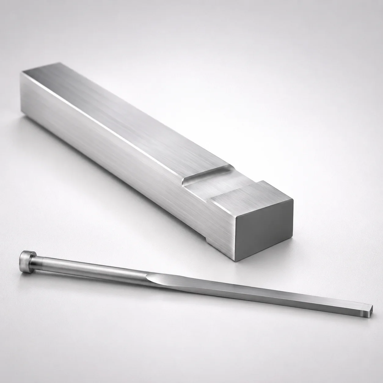
JIS Standard M2 Steel Gas Release Rectangular Ejector Pins
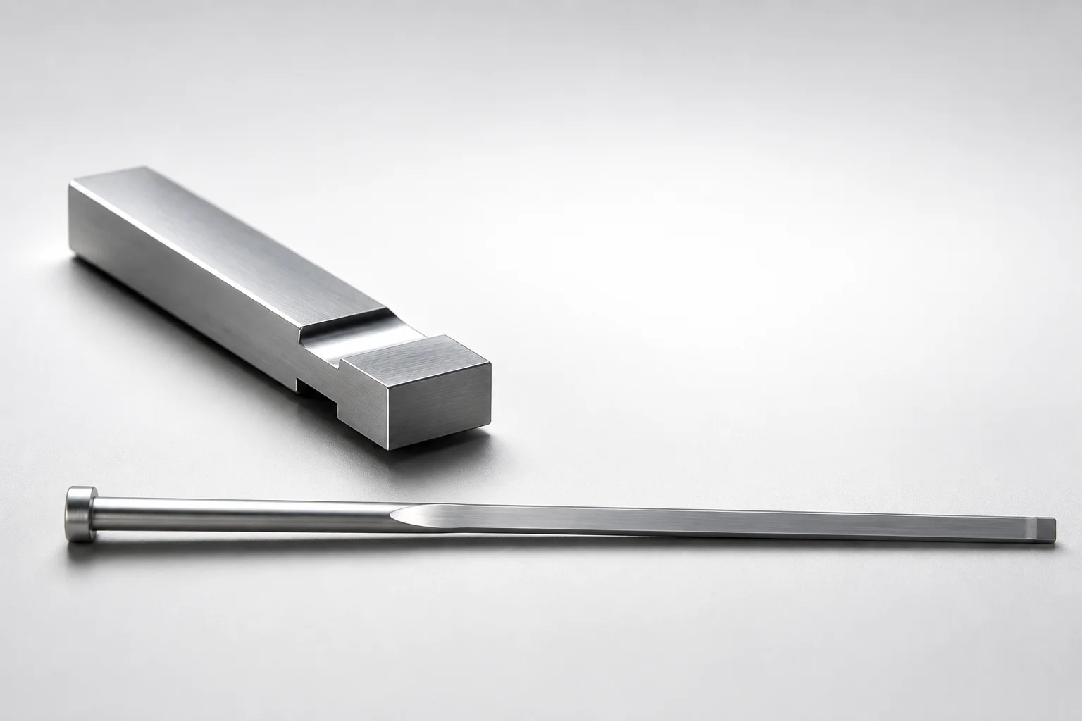
JIS Standard SKH51 Steel Gas Release Rectangular Ejector Pins
Need Custom Specifications?
Our engineering team can help with custom configurations, material selection, and volume pricing.