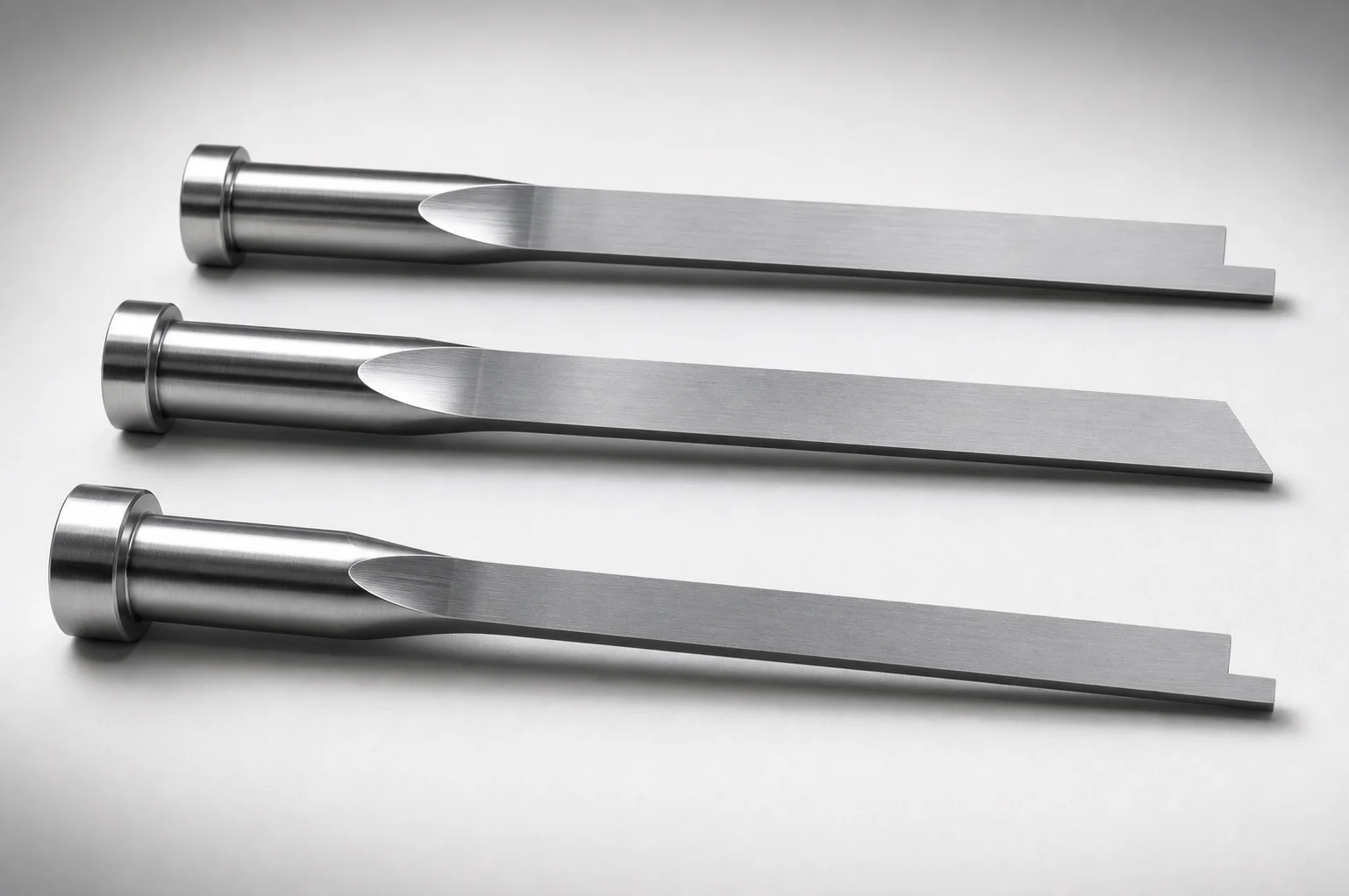
JIS Standard SKH51 Steel Tip-Processed Rectangular Ejector Pins
Tip-Processed rectangular ejector pins (SKH51 steel) are engineered for reliable ejection with controlled tip geometry. Designed for precision mold build-ups under JIS-based manufacturing requirements.
- Tip processing supports secure engagement and consistent ejection in molds
- SKH51 steel construction with durable wear resistance and machining stability
- Controlled tip-related dimension tolerance reference supports tight assembly fit
- JIS standard rectangular ejector pin design for typical injection tooling
Specifications
420 configurations available
| Head Thickness | P (Tip) (mm) | W (Tip) (mm) | D (Shaft Diameter) (mm) | Tip Shape | L (L dimension) (mm) | Dimension N (mm) | A (mm) | Dimension C (mm) | G (°) | Dimension R (mm) | Dimension V (mm) | type |
|---|---|---|---|---|---|---|---|---|---|---|---|---|
| 4mm(T4) | 0.8 ~ 1.8 | 0.6 ~ 1.72 | 2 | 1X | 50 ~ 250 | 33 ~ 240 | - | - | 1 ~ 45 | - | - | - |
| 4mm(T4) | 0.8 ~ 2.3 | 0.6 ~ 2.26 | 2.5 | 1X | 50 ~ 250 | 33 ~ 240 | - | - | 1 ~ 45 | - | - | - |
| 4mm(T4) | 0.8 ~ 2.8 | 0.6 ~ 2.8 | 3 | 1X | 50 ~ 300 | 33 ~ 250 | - | - | 1 ~ 45 | - | - | - |
| 4mm(T4) | 1 ~ 3.3 | 0.6 ~ 3.3 | 3.5 | 1X | 50 ~ 300 | 33 ~ 250 | - | - | 1 ~ 45 | - | - | - |
| 4mm(T4) | 1 ~ 3.8 | 0.6 ~ 3.8 | 4 | 1X | 50 ~ 300 | 33 ~ 250 | - | - | 1 ~ 45 | - | - | - |
| 4mm(T4) | 1.2 ~ 4.3 | 0.6 ~ 4.3 | 4.5 | 1X | 50 ~ 300 | 33 ~ 250 | - | - | 1 ~ 45 | - | - | - |
| 4mm(T4) | 1.5 ~ 4.8 | 0.6 ~ 4.8 | 5 | 1X | 50 ~ 300 | 33 ~ 250 | - | - | 1 ~ 45 | - | - | - |
| 4mm(T4) | 1.5 ~ 5.3 | 0.8 ~ 5.3 | 5.5 | 1X | 50 ~ 300 | 33 ~ 250 | - | - | 1 ~ 45 | - | - | - |
| 4mm(T4) | 2 ~ 5.8 | 0.8 ~ 5.8 | 6 | 1X | 50 ~ 300 | 33 ~ 250 | - | - | 1 ~ 45 | - | - | - |
| 4mm(T4) | 2 ~ 6.3 | 0.8 ~ 6.3 | 6.5 | 1X | 50 ~ 300 | 40 ~ 250 | - | - | 1 ~ 45 | - | - | - |
| 4mm(T4) | 2.3 ~ 6.8 | 0.8 ~ 6.8 | 7 | 1X | 50 ~ 300 | 40 ~ 250 | - | - | 1 ~ 45 | - | - | - |
| 4mm(T4) | 2.3 ~ 7.8 | 0.8 ~ 7.8 | 8 | 1X | 50 ~ 300 | 40 ~ 250 | - | - | 1 ~ 45 | - | - | - |
| 4mm(T4) | 2.3 ~ 8.3 | 0.8 ~ 8.07 | 8.5 | 1X | 50 ~ 300 | 40 ~ 290 | - | - | 1 ~ 45 | - | - | - |
| 4mm(T4) | 3 ~ 9.8 | 0.8 ~ 9.8 | 10 | 1X | 50 ~ 300 | 40 ~ 250 | - | - | 1 ~ 45 | - | - | - |
| 4mm(T4) | 3 ~ 10.3 | 0.8 ~ 9.95 | 10.5 | 1X | 50 ~ 300 | 40 ~ 290 | - | - | 1 ~ 45 | - | - | - |
| 4mm(T4) | 0.8 ~ 1.8 | 0.6 ~ 1.72 | 2 | 1Y | 50 ~ 250 | 33 ~ 240 | - | - | 1 ~ 45 | - | - | - |
| 4mm(T4) | 0.8 ~ 2.3 | 0.6 ~ 2.26 | 2.5 | 1Y | 50 ~ 250 | 33 ~ 240 | - | - | 1 ~ 45 | - | - | - |
| 4mm(T4) | 0.8 ~ 2.8 | 0.6 ~ 2.8 | 3 | 1Y | 50 ~ 300 | 33 ~ 250 | - | - | 1 ~ 45 | - | - | - |
| 4mm(T4) | 1 ~ 3.3 | 0.6 ~ 3.3 | 3.5 | 1Y | 50 ~ 300 | 33 ~ 250 | - | - | 1 ~ 45 | - | - | - |
| 4mm(T4) | 1 ~ 3.8 | 0.6 ~ 3.8 | 4 | 1Y | 50 ~ 300 | 33 ~ 250 | - | - | 1 ~ 45 | - | - | - |
| 4mm(T4) | 1.2 ~ 4.3 | 0.6 ~ 4.3 | 4.5 | 1Y | 50 ~ 300 | 33 ~ 250 | - | - | 1 ~ 45 | - | - | - |
| 4mm(T4) | 1.5 ~ 4.8 | 0.6 ~ 4.8 | 5 | 1Y | 50 ~ 300 | 33 ~ 250 | - | - | 1 ~ 45 | - | - | - |
| 4mm(T4) | 1.5 ~ 5.3 | 0.8 ~ 5.3 | 5.5 | 1Y | 50 ~ 300 | 33 ~ 250 | - | - | 1 ~ 45 | - | - | - |
| 4mm(T4) | 2 ~ 5.8 | 0.8 ~ 5.8 | 6 | 1Y | 50 ~ 300 | 33 ~ 250 | - | - | 1 ~ 45 | - | - | - |
| 4mm(T4) | 2 ~ 6.3 | 0.8 ~ 6.3 | 6.5 | 1Y | 50 ~ 300 | 40 ~ 250 | - | - | 1 ~ 45 | - | - | - |
| 4mm(T4) | 2.3 ~ 6.8 | 0.8 ~ 6.8 | 7 | 1Y | 50 ~ 300 | 40 ~ 250 | - | - | 1 ~ 45 | - | - | - |
| 4mm(T4) | 2.3 ~ 7.8 | 0.8 ~ 7.8 | 8 | 1Y | 50 ~ 300 | 40 ~ 250 | - | - | 1 ~ 45 | - | - | - |
| 4mm(T4) | 2.3 ~ 8.3 | 0.8 ~ 8.07 | 8.5 | 1Y | 50 ~ 300 | 40 ~ 290 | - | - | 1 ~ 45 | - | - | - |
| 4mm(T4) | 3 ~ 9.8 | 0.8 ~ 9.8 | 10 | 1Y | 50 ~ 300 | 40 ~ 250 | - | - | 1 ~ 45 | - | - | - |
| 4mm(T4) | 3 ~ 10.3 | 0.8 ~ 9.95 | 10.5 | 1Y | 50 ~ 300 | 40 ~ 290 | - | - | 1 ~ 45 | - | - | - |
| 4mm(T4) | 0.8 ~ 1.8 | 0.6 ~ 1.72 | 2 | 2X | 50 ~ 250 | 33 ~ 240 | - | - | 45 ~ 90 | - | 0.3 ~ 1.79 | - |
| 4mm(T4) | 0.8 ~ 2.3 | 0.6 ~ 2.26 | 2.5 | 2X | 50 ~ 250 | 33 ~ 240 | - | - | 45 ~ 90 | - | 0.3 ~ 2.29 | - |
| 4mm(T4) | 1 ~ 2.8 | 0.6 ~ 2.72 | 3 | 2X | 50 ~ 300 | 33 ~ 250 | - | - | 45 ~ 90 | - | 0.3 ~ 2.79 | - |
| 4mm(T4) | 1 ~ 3.3 | 0.6 ~ 3.24 | 3.5 | 2X | 50 ~ 300 | 33 ~ 290 | - | - | 45 ~ 90 | - | 0.3 ~ 3.29 | - |
| 4mm(T4) | 1 ~ 3.8 | 0.6 ~ 3.76 | 4 | 2X | 50 ~ 300 | 33 ~ 290 | - | - | 45 ~ 90 | - | 0.3 ~ 3.79 | - |
| 4mm(T4) | 1.2 ~ 4.3 | 0.6 ~ 4.23 | 4.5 | 2X | 50 ~ 300 | 33 ~ 290 | - | - | 45 ~ 90 | - | 0.3 ~ 4.29 | - |
| 4mm(T4) | 1.5 ~ 4.8 | 0.6 ~ 4.66 | 5 | 2X | 50 ~ 300 | 33 ~ 290 | - | - | 45 ~ 90 | - | 0.3 ~ 4.79 | - |
| 4mm(T4) | 1.8 ~ 5.3 | 0.8 ~ 5.09 | 5.5 | 2X | 50 ~ 300 | 33 ~ 250 | - | - | 45 ~ 90 | - | 0.3 ~ 5.29 | - |
| 4mm(T4) | 2 ~ 5.8 | 0.8 ~ 5.55 | 6 | 2X | 50 ~ 300 | 33 ~ 250 | - | - | 45 ~ 90 | - | 0.3 ~ 5.79 | - |
| 4mm(T4) | 2 ~ 6.3 | 0.8 ~ 6.07 | 6.5 | 2X | 50 ~ 300 | 40 ~ 290 | - | - | 45 ~ 90 | - | 0.3 ~ 6.29 | - |
| 4mm(T4) | 2.3 ~ 6.8 | 0.8 ~ 6.5 | 7 | 2X | 50 ~ 300 | 40 ~ 290 | - | - | 45 ~ 90 | - | 0.3 ~ 6.79 | - |
| 4mm(T4) | 2.3 ~ 7.8 | 0.8 ~ 7.55 | 8 | 2X | 50 ~ 300 | 40 ~ 290 | - | - | 45 ~ 90 | - | 0.3 ~ 7.79 | - |
| 4mm(T4) | 2.3 ~ 8.3 | 0.8 ~ 8.07 | 8.5 | 2X | 50 ~ 300 | 40 ~ 290 | - | - | 45 ~ 90 | - | 0.3 ~ 8.29 | - |
| 4mm(T4) | 3 ~ 9.8 | 0.8 ~ 9.43 | 10 | 2X | 50 ~ 300 | 40 ~ 290 | - | - | 45 ~ 90 | - | 0.3 ~ 9.79 | - |
| 4mm(T4) | 3 ~ 10.3 | 0.8 ~ 9.95 | 10.5 | 2X | 50 ~ 300 | 40 ~ 290 | - | - | 45 ~ 90 | - | 0.3 ~ 10.29 | - |
| 4mm(T4) | 0.8 ~ 1.8 | 0.6 ~ 1.72 | 2 | 2Y | 50 ~ 250 | 33 ~ 240 | - | - | 45 ~ 90 | - | 0.3 ~ 1.71 | - |
| 4mm(T4) | 0.8 ~ 2.3 | 0.6 ~ 2.26 | 2.5 | 2Y | 50 ~ 250 | 33 ~ 240 | - | - | 45 ~ 90 | - | 0.3 ~ 2.25 | - |
| 4mm(T4) | 1 ~ 2.8 | 0.6 ~ 2.72 | 3 | 2Y | 50 ~ 300 | 33 ~ 250 | - | - | 45 ~ 90 | - | 0.3 ~ 2.71 | - |
| 4mm(T4) | 1 ~ 3.3 | 0.6 ~ 3.24 | 3.5 | 2Y | 50 ~ 300 | 33 ~ 290 | - | - | 45 ~ 90 | - | 0.3 ~ 3.23 | - |
| 4mm(T4) | 1 ~ 3.8 | 0.6 ~ 3.76 | 4 | 2Y | 50 ~ 300 | 33 ~ 290 | - | - | 45 ~ 90 | - | 0.3 ~ 3.75 | - |
Product Guide
Application Scenarios+
Tip-processed rectangular ejector pins are used in injection mold tooling where repeatable stripping depends on stable tip-to-cavity engagement. In automotive connector and housing molds, the processed tip geometry helps ensure consistent ejection timing and reduced risk of sticking during high-cycle production, especially when the pin path is guided through rectangular blade features.
For electronics enclosures and appliance components, these pins support fine alignment in ejector systems because the product is dimensioned for mold build-up with controlled tip-related tolerance references. The JIS-standard rectangular form factor also suits conventional ejector layouts used in multi-cavity assemblies.
In medical device housings and other precision parts, stable engagement at the leading tip can reduce scuffing and uneven release. The SKH51 steel base supports machining stability, which is important when integrating pins with ejector blades and guide interfaces.
- Use where tip contact consistency is critical for reliable ejection
- Rectangular layout fits common ejector blade assembly patterns
- SKH51 tip-processed variant is suited for stable stripping under controlled fit requirements
Material & Process Details+
This variant uses JIS Standard SKH51 tip-processed tool steel. SKH51 is generally considered equivalent to AISI M2 high-speed steel in performance class, providing a strong balance of wear resistance and cutting/machining stability for small ejector features.
- Wear resistance: high hardness supports abrasion resistance at the tip during repeated sliding/engagement.
- Toughness trade-off: as hardness increases, impact toughness can decrease; proper pin support and engagement length help manage cracking risk.
- Heat treatment state: typically delivered after the manufacturer’s hardening and tempering to a hardened condition appropriate for HRC targets used in tool steel ejector applications.
Hardness (HRC): the exact HRC value is not provided in the supplied data, so it should be confirmed against the purchase specification for your assembly requirements. If you compare alternatives, steels with lower alloy content may offer better toughness, while SKH51/M2-class favors higher wear resistance at the tip.
Sizing & Selection Guide+
Start selection by matching the shaft diameter (D) and overall length (L) to your mold ejector blade and support design. Available ranges are D = 2 to 10.5 mm, with L = 50 to 250 mm (also available up to L = 300 mm in some configurations).
Then verify the tip geometry for the required engagement: P (Tip) = 0.8 to 3 mm and W (Tip) = 0.6 to 0.8 mm. The tip shape can be selected as 1 to 7, which should correspond to your cavity stripping interface and the way the ejector pin seats in the ejector blade.
- Head thickness: choose from T4 (4 mm), or 4 / 6 / 8 mm (JIS) depending on stack-up height in your ejector plate.
- Offset/feature dimensions: confirm N options (e.g., 33–240, 33–250, 40–250, 40–290, 33–290, 33–230 mm) and curvature R = 0.5 to 3 mm.
- Tolerance/fit: dimension A is 0 to 0.3 mm and dimension C is 0.5 to 5 mm (or 0.3 to 5 mm depending on configuration). Use these values to align with your guide clearance and assembly requirements; confirm allowable clearance in your mold drawings.
Frequently Asked Questions
Which tip dimensions (P and W) should I match to my ejector blade engagement area?+
How do I choose the correct shaft diameter D and length L for my ejector system?+
What head thickness options are available and how do they affect stack-up height?+
How do tip shape selection and curvature radius R influence ejection stability?+
Is SKH51 suitable for wear resistance at the ejector tip, and what should I verify about hardness?+
Related Products
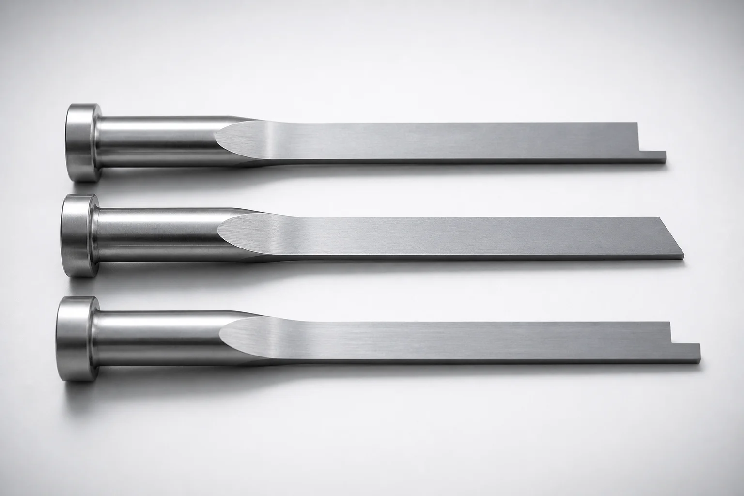
JIS Standard SKH51 Steel Precision Rectangular Ejector Pins with Tip Processed
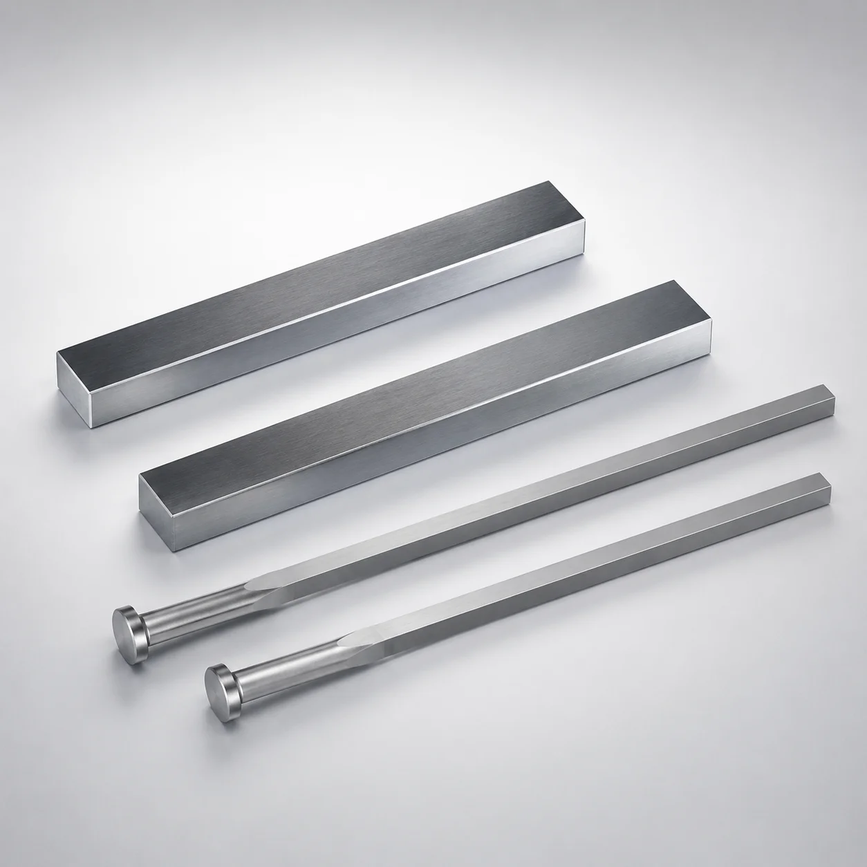
JIS Standard SKH51 Steel Rectangular Ejector Pins with Engraving
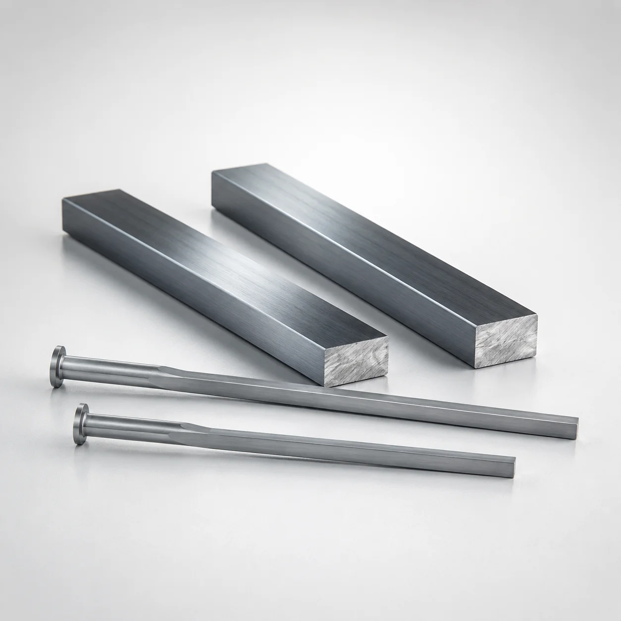
M2 Steel Rectangular Ejector Pins with Engraving - Flat-Head
JIS Standard SKH51 Steel D-Shaped Ejector Pins
JIS Standard M2 Steel Gas Release Rectangular Ejector Pins
JIS Standard SKH51 Steel Gas Release Rectangular Ejector Pins
Need Custom Specifications?
Our engineering team can help with custom configurations, material selection, and volume pricing.