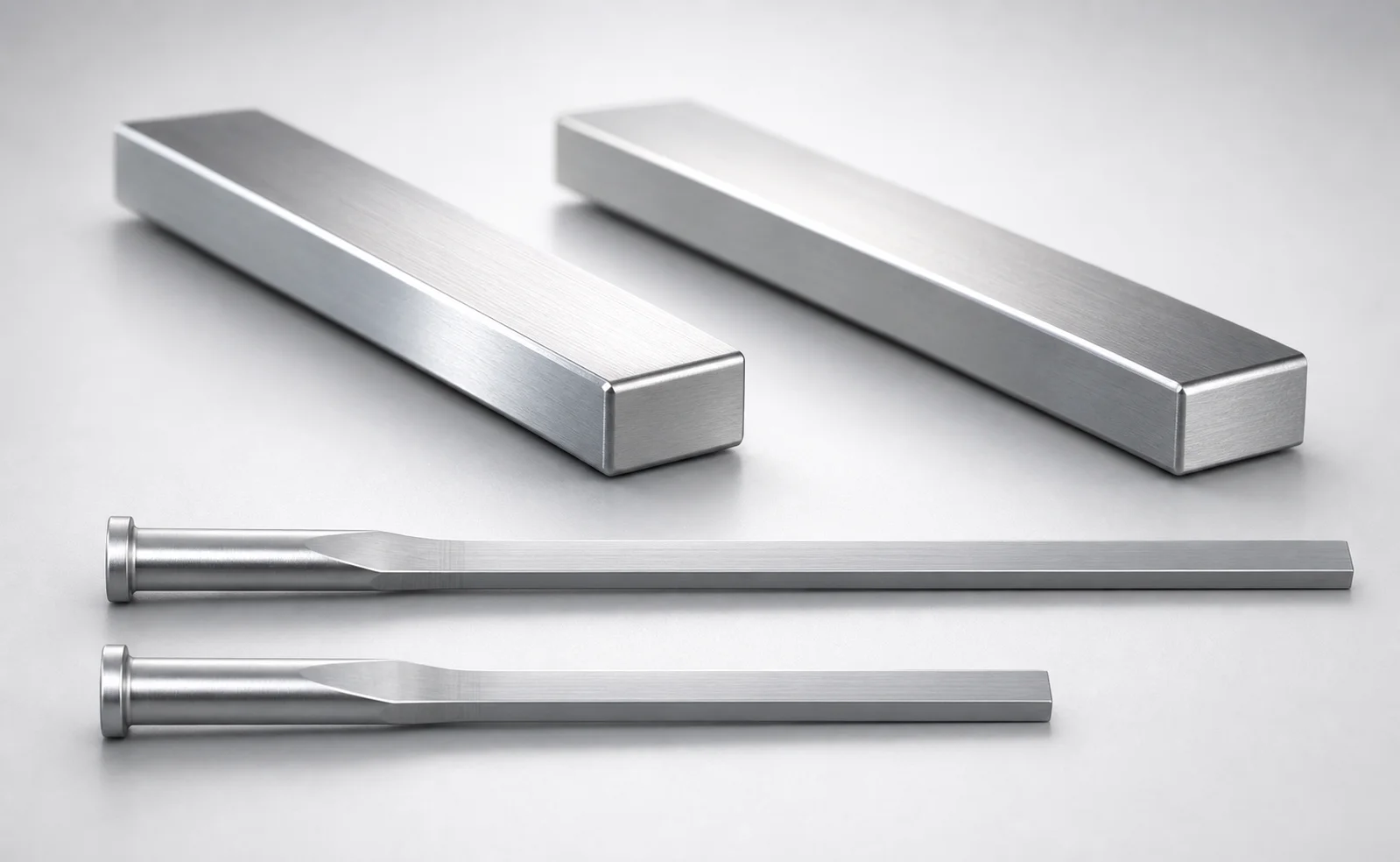
M2 Steel R-Chamfered Rectangular Ejector Pins with Engraving
R-Chamfered rectangular ejector pins with engraving (M2 steel) provide reliable ejection support while enabling engraved character marking for traceable mold operation and part identification. The precise rectangular tip geometry helps maintain consistent alignment under cycle loads.
- R-chamfered rectangular tip supports stable positioning during ejection cycles
- Engraving format: Designation by WOS for clear traceability
- Durable SKH51 hardened steel resists wear for long service life
- Trimmed pin design with 0/-0.01 tolerance reference for dependable assembly
Specifications
154 configurations available
| P (Tip) (mm) | W (Tip) (mm) | D (Shaft Diameter) (mm) | Character Engraving Type | Number of engraving characters | R-Chamfered Rectangular Position | L (L dimension) (mm) | Dimension N (mm) | Engraving character designation | R (Corner R of the tip corner) (mm) | type |
|---|---|---|---|---|---|---|---|---|---|---|
| 0.8 ~ 1.7 | 0.3 ~ 1.7 | 2 | Concave character | 1 characters | FR | 40 ~ 250 | 23 ~ 200 | ※Designation by WOS | 0.1 ~ 0.3 | - |
| 0.8 ~ 2.2 | 0.3 ~ 2.2 | 2.5 | Concave character | 1 characters | FR | 40 ~ 250 | 26 ~ 200 | ※Designation by WOS | 0.1 ~ 0.3 | - |
| 1 ~ 2.7 | 0.3 ~ 2.7 | 3 | Concave character | 1 characters | FR | 40 ~ 250 | 27 ~ 200 | ※Designation by WOS | 0.1 ~ 0.3 | - |
| 1 ~ 3.2 | 0.3 ~ 3.2 | 3.5 | Concave character | 1 characters | FR | 40 ~ 250 | 27 ~ 200 | ※Designation by WOS | 0.1 ~ 0.3 | - |
| 1 ~ 3.7 | 0.3 ~ 3.7 | 4 | Concave character | 1 characters | FR | 40 ~ 250 | 29 ~ 200 | ※Designation by WOS | 0.1 ~ 0.3 | - |
| 1.2 ~ 4.2 | 0.3 ~ 4.2 | 4.5 | Concave character | 1 characters | FR | 40 ~ 250 | 29 ~ 200 | ※Designation by WOS | 0.1 ~ 0.3 | - |
| 1.5 ~ 4.8 | 0.4 ~ 4.8 | 5 | Concave character | 1 characters | FR | 50 ~ 250 | 31 ~ 200 | ※Designation by WOS | 0.1 ~ 0.3 | - |
| 1.8 ~ 5.3 | 0.4 ~ 5.3 | 5.5 | Concave character | 1 characters | FR | 50 ~ 250 | 31 ~ 200 | ※Designation by WOS | 0.1 ~ 0.3 | - |
| 2 ~ 5.8 | 0.5 ~ 5.8 | 6 | Concave character | 1 characters | FR | 50 ~ 250 | 33 ~ 200 | ※Designation by WOS | 0.1 ~ 0.3 | - |
| 2 ~ 6.3 | 0.5 ~ 6.3 | 6.5 | Concave character | 1 characters | FR | 50 ~ 250 | 40 ~ 200 | ※Designation by WOS | 0.1 ~ 0.3 | - |
| 2.3 ~ 6.8 | 0.5 ~ 6.8 | 7 | Concave character | 1 characters | FR | 50 ~ 250 | 40 ~ 200 | ※Designation by WOS | 0.1 ~ 0.3 | - |
| 2.3 ~ 7.8 | 0.5 ~ 7.8 | 8 | Concave character | 1 characters | FR | 50 ~ 250 | 40 ~ 200 | ※Designation by WOS | 0.1 ~ 0.3 | - |
| 3 ~ 9.8 | 0.5 ~ 9.8 | 10 | Concave character | 1 characters | FR | 50 ~ 250 | 40 ~ 200 | ※Designation by WOS | 0.1 ~ 0.3 | - |
| 0.8 ~ 1.8 | 0.3 ~ 1.8 | 2 | Concave character (Sequential numbering) | 1 characters | FR | 50 ~ 250 | 23 ~ 200 | ※Designation by WOS | 0.1 ~ 0.3 | - |
| 0.8 ~ 2.3 | 0.3 ~ 2.3 | 2.5 | Concave character (Sequential numbering) | 1 characters | FR | 50 ~ 250 | 26 ~ 200 | ※Designation by WOS | 0.1 ~ 0.3 | - |
| 1 ~ 2.8 | 0.3 ~ 2.8 | 3 | Concave character (Sequential numbering) | 1 characters | FR | 50 ~ 250 | 27 ~ 200 | ※Designation by WOS | 0.1 ~ 0.3 | - |
| 1 ~ 3.3 | 0.3 ~ 3.3 | 3.5 | Concave character (Sequential numbering) | 1 characters | FR | 50 ~ 250 | 27 ~ 200 | ※Designation by WOS | 0.1 ~ 0.3 | - |
| 1 ~ 3.8 | 0.3 ~ 3.8 | 4 | Concave character (Sequential numbering) | 1 characters | FR | 50 ~ 250 | 29 ~ 200 | ※Designation by WOS | 0.1 ~ 0.3 | - |
| 1.2 ~ 4.3 | 0.3 ~ 4.3 | 4.5 | Concave character (Sequential numbering) | 1 characters | FR | 50 ~ 250 | 29 ~ 200 | ※Designation by WOS | 0.1 ~ 0.3 | - |
| 1.5 ~ 4.8 | 0.4 ~ 4.8 | 5 | Concave character (Sequential numbering) | 1 characters | FR | 50 ~ 250 | 31 ~ 200 | ※Designation by WOS | 0.1 ~ 0.3 | - |
| 1.8 ~ 5.3 | 0.4 ~ 5.3 | 5.5 | Concave character (Sequential numbering) | 1 characters | FR | 50 ~ 250 | 31 ~ 200 | ※Designation by WOS | 0.1 ~ 0.3 | - |
| 2 ~ 5.8 | 0.5 ~ 5.8 | 6 | Concave character (Sequential numbering) | 1 characters | FR | 50 ~ 250 | 33 ~ 200 | ※Designation by WOS | 0.1 ~ 0.3 | - |
| 2 ~ 6.3 | 0.5 ~ 6.3 | 6.5 | Concave character (Sequential numbering) | 1 characters | FR | 50 ~ 250 | 40 ~ 200 | ※Designation by WOS | 0.1 ~ 0.3 | - |
| 2.3 ~ 6.8 | 0.5 ~ 6.8 | 7 | Concave character (Sequential numbering) | 1 characters | FR | 50 ~ 250 | 40 ~ 200 | ※Designation by WOS | 0.1 ~ 0.3 | - |
| 2.3 ~ 7.8 | 0.5 ~ 7.8 | 8 | Concave character (Sequential numbering) | 1 characters | FR | 50 ~ 250 | 40 ~ 200 | ※Designation by WOS | 0.1 ~ 0.3 | - |
| 3 ~ 9.8 | 0.5 ~ 9.8 | 10 | Concave character (Sequential numbering) | 1 characters | FR | 50 ~ 250 | 40 ~ 200 | ※Designation by WOS | 0.1 ~ 0.3 | - |
| 0.8 ~ 1.7 | 0.3 ~ 1.7 | 2 | Concave character | 2 characters | FR | 40 ~ 250 | 23 ~ 200 | ※Designation by WOS | 0.1 ~ 0.3 | - |
| 0.8 ~ 2.2 | 0.3 ~ 2.2 | 2.5 | Concave character | 2 characters | FR | 40 ~ 250 | 26 ~ 200 | ※Designation by WOS | 0.1 ~ 0.3 | - |
| 1 ~ 2.7 | 0.3 ~ 2.7 | 3 | Concave character | 2 characters | FR | 40 ~ 250 | 27 ~ 200 | ※Designation by WOS | 0.1 ~ 0.3 | - |
| 1 ~ 3.2 | 0.3 ~ 3.2 | 3.5 | Concave character | 2 characters | FR | 40 ~ 250 | 27 ~ 200 | ※Designation by WOS | 0.1 ~ 0.3 | - |
| 1 ~ 3.7 | 0.3 ~ 3.7 | 4 | Concave character | 2 characters | FR | 40 ~ 250 | 29 ~ 200 | ※Designation by WOS | 0.1 ~ 0.3 | - |
| 1.2 ~ 4.2 | 0.3 ~ 4.2 | 4.5 | Concave character | 2 characters | FR | 40 ~ 250 | 29 ~ 200 | ※Designation by WOS | 0.1 ~ 0.3 | - |
| 1.5 ~ 4.8 | 0.4 ~ 4.8 | 5 | Concave character | 2 characters | FR | 50 ~ 250 | 31 ~ 200 | ※Designation by WOS | 0.1 ~ 0.3 | - |
| 1.8 ~ 5.3 | 0.4 ~ 5.3 | 5.5 | Concave character | 2 characters | FR | 50 ~ 250 | 31 ~ 200 | ※Designation by WOS | 0.1 ~ 0.3 | - |
| 2 ~ 5.8 | 0.5 ~ 5.8 | 6 | Concave character | 2 characters | FR | 50 ~ 250 | 33 ~ 200 | ※Designation by WOS | 0.1 ~ 0.3 | - |
| 2 ~ 6.3 | 0.5 ~ 6.3 | 6.5 | Concave character | 2 characters | FR | 50 ~ 250 | 40 ~ 200 | ※Designation by WOS | 0.1 ~ 0.3 | - |
| 2.3 ~ 6.8 | 0.5 ~ 6.8 | 7 | Concave character | 2 characters | FR | 50 ~ 250 | 40 ~ 200 | ※Designation by WOS | 0.1 ~ 0.3 | - |
| 2.3 ~ 7.8 | 0.5 ~ 7.8 | 8 | Concave character | 2 characters | FR | 50 ~ 250 | 40 ~ 200 | ※Designation by WOS | 0.1 ~ 0.3 | - |
| 3 ~ 9.8 | 0.5 ~ 9.8 | 10 | Concave character | 2 characters | FR | 50 ~ 250 | 40 ~ 200 | ※Designation by WOS | 0.1 ~ 0.3 | - |
| 0.8 ~ 1.8 | 0.3 ~ 1.8 | 2 | Concave character (Sequential numbering) | 2 characters | FR | 50 ~ 250 | 23 ~ 200 | ※Designation by WOS | 0.1 ~ 0.3 | - |
| 0.8 ~ 2.3 | 0.3 ~ 2.3 | 2.5 | Concave character (Sequential numbering) | 2 characters | FR | 50 ~ 250 | 26 ~ 200 | ※Designation by WOS | 0.1 ~ 0.3 | - |
| 1 ~ 2.8 | 0.3 ~ 2.8 | 3 | Concave character (Sequential numbering) | 2 characters | FR | 50 ~ 250 | 27 ~ 200 | ※Designation by WOS | 0.1 ~ 0.3 | - |
| 1 ~ 3.3 | 0.3 ~ 3.3 | 3.5 | Concave character (Sequential numbering) | 2 characters | FR | 50 ~ 250 | 27 ~ 200 | ※Designation by WOS | 0.1 ~ 0.3 | - |
| 1 ~ 3.8 | 0.3 ~ 3.8 | 4 | Concave character (Sequential numbering) | 2 characters | FR | 50 ~ 250 | 29 ~ 200 | ※Designation by WOS | 0.1 ~ 0.3 | - |
| 1.2 ~ 4.3 | 0.3 ~ 4.3 | 4.5 | Concave character (Sequential numbering) | 2 characters | FR | 50 ~ 250 | 29 ~ 200 | ※Designation by WOS | 0.1 ~ 0.3 | - |
| 1.5 ~ 4.8 | 0.4 ~ 4.8 | 5 | Concave character (Sequential numbering) | 2 characters | FR | 50 ~ 250 | 31 ~ 200 | ※Designation by WOS | 0.1 ~ 0.3 | - |
| 1.8 ~ 5.3 | 0.4 ~ 5.3 | 5.5 | Concave character (Sequential numbering) | 2 characters | FR | 50 ~ 250 | 31 ~ 200 | ※Designation by WOS | 0.1 ~ 0.3 | - |
| 2 ~ 5.8 | 0.5 ~ 5.8 | 6 | Concave character (Sequential numbering) | 2 characters | FR | 50 ~ 250 | 33 ~ 200 | ※Designation by WOS | 0.1 ~ 0.3 | - |
| 2 ~ 6.3 | 0.5 ~ 6.3 | 6.5 | Concave character (Sequential numbering) | 2 characters | FR | 50 ~ 250 | 40 ~ 200 | ※Designation by WOS | 0.1 ~ 0.3 | - |
| 2.3 ~ 6.8 | 0.5 ~ 6.8 | 7 | Concave character (Sequential numbering) | 2 characters | FR | 50 ~ 250 | 40 ~ 200 | ※Designation by WOS | 0.1 ~ 0.3 | - |
Product Guide
Application Scenarios+
This R-chamfered rectangular ejector pin variant is used in injection mold tooling where consistent ejection force transfer and part identification marking both matter. The rectangular tip maintains stable contact during strokes, while the engraving provides traceable mold-part designation on the molded component.
- Automotive and appliance housings: Suitable for ejecting flat features and localized bosses without tip wobble. The M2-grade hardened steel (SKH51) resists tip wear under repeated cycle loading, helping preserve alignment.
- Electronics housings with labeling zones: The concave character engraving (sequential numbering available) supports readable identification for incoming inspection or assembly traceability.
- Industrial connector or cover inserts: The R-chamfered tip position options (FR, WR) allow fitting to cavity/core layouts while supporting clean part release around edges.
Overall, the hardened SKH51 M2 steel construction and tight dimensional control support long-running molds that require both reliable ejection and consistent identification marks.
Material & Process Details+
Constructed from SKH51, this ejector pin uses an M2 tool steel formulation. SKH51 is commonly treated as an AISI M2 equivalent in mold tooling practice, offering a balanced mix of high hardness, wear resistance, and moderate toughness.
- Hardness: Typical hardened-and-tempered tool-steel use provides durable HRC levels for sliding and contact wear (exact HRC is not specified in the provided data).
- Wear resistance vs. toughness: Higher hardness improves scuffing and corner durability, but can reduce impact toughness if shock loads are severe. The rectangular tip and corner radius (R = 0.1 ~ 0.3 mm) help reduce stress concentration.
- Manufacturing process: Heat treated to a hardened state suitable for ejector service, then ground/finished to the specified tip geometry and dimensions to support stable ejection alignment.
If alternative steels are considered for higher toughness, trade-offs often appear as reduced wear resistance; for most identification-marked ejector applications, SKH51’s wear-focused performance is the priority.
Sizing & Selection Guide+
Select pin size by mapping the ejector function (support/ejection) and the marking geometry (engraving placement) to your cavity/core design. Use the provided ranges to ensure the pin tip and shaft fit the guide/receiver and that the engraved characters land within the intended marking area.
- Tip geometry: Choose P (tip) from 0.8 ~ 3 mm, and W (tip) from 0.3 ~ 0.5 mm. Set the corner radius to R = 0.1 ~ 0.3 mm to control contact and edge loading.
- Shaft fit: Select D (shaft diameter) from 2 ~ 10 mm. Confirm that your bushing/guide bore tolerances accommodate the chosen diameter and allow stable movement without excessive clearance.
- Marking/engagement length: Match L (L dimension) (either 40 ~ 250 or 50 ~ 250) and Dimension N = 23 ~ 40 mm to your stack-up so the pin engages the cavity surface at the correct stroke.
Engraving format is fixed as ※Designation by WOS and the number of characters is selectable (1–5). The R-chamfered position is selectable as FR or WR, which must align with the mold cavity/core orientation.
Frequently Asked Questions
How do I choose the correct tip size (P and W) for stable ejection without damaging the engraved marking area?+
What does “※Designation by WOS” engraving mean, and what character count options are available?+
How should I select shaft diameter D and pin length L to ensure proper engagement in my mold stack-up?+
When should I choose FR versus WR R-chamfered rectangular position?+
What steel grade is used, and how does SKH51 compare to other tool steels for ejector pin service?+
Related Products
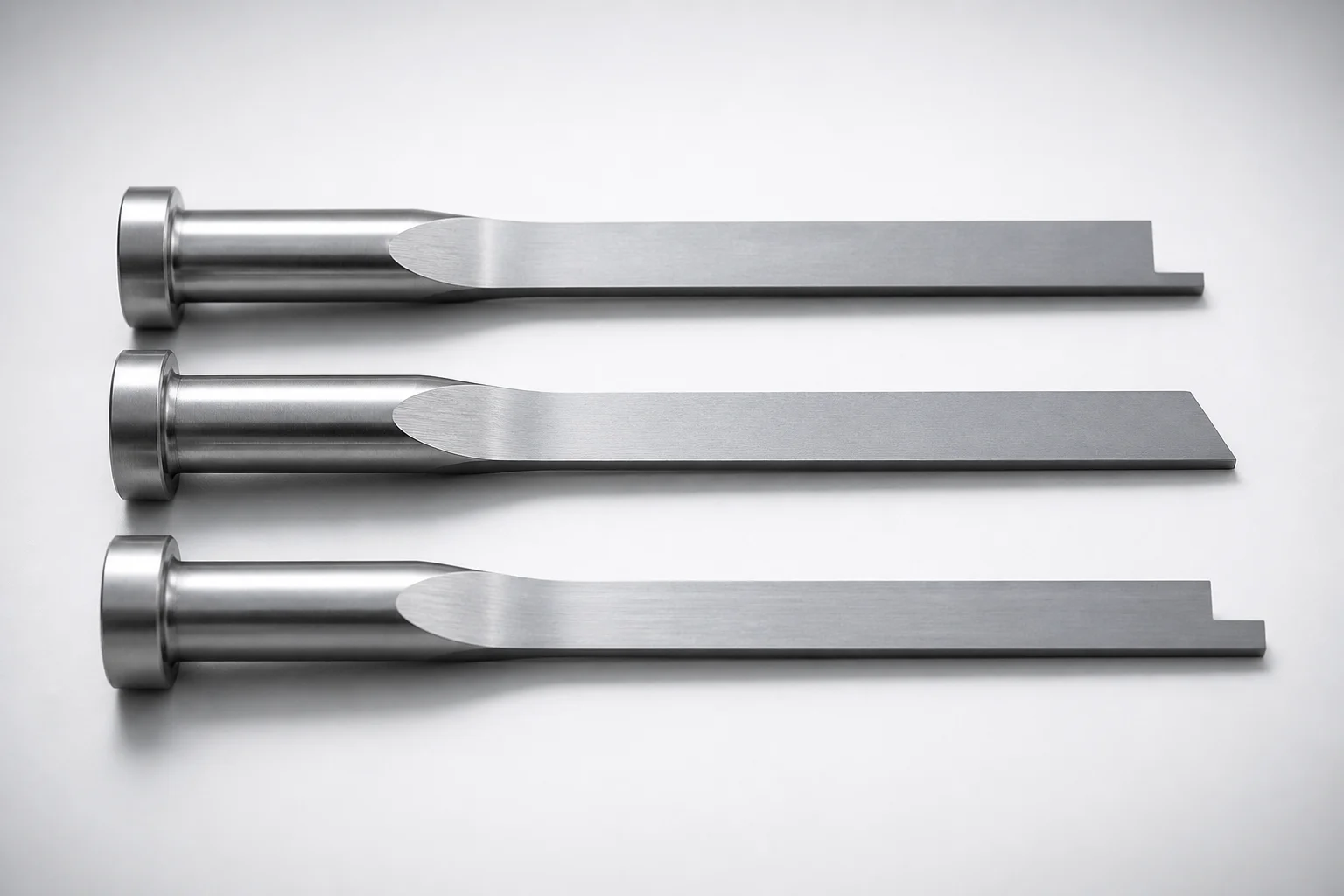
JIS Standard SKH51 Steel Precision Rectangular Ejector Pins with Tip Processed
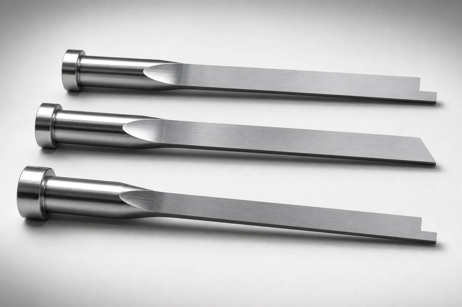
JIS Standard SKH51 Steel Tip-Processed Rectangular Ejector Pins
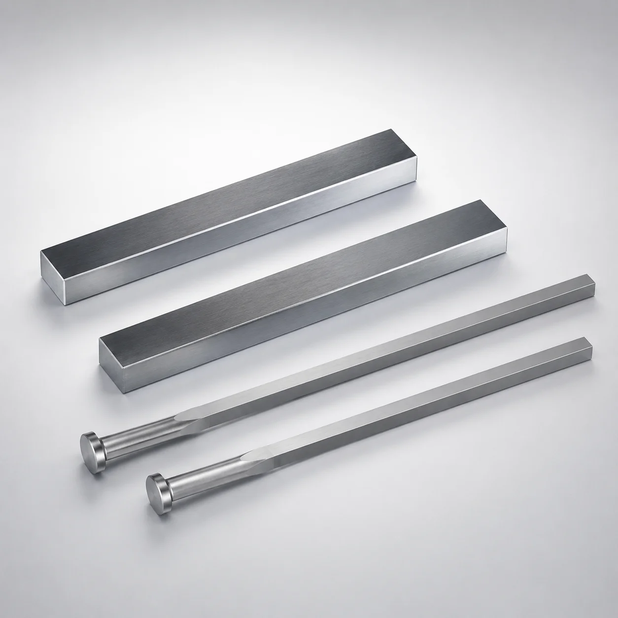
JIS Standard SKH51 Steel Rectangular Ejector Pins with Engraving
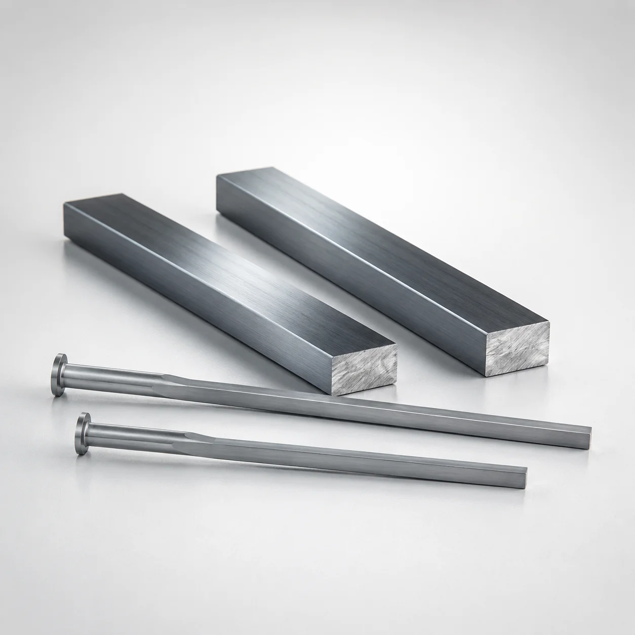
M2 Steel Rectangular Ejector Pins with Engraving - Flat-Head
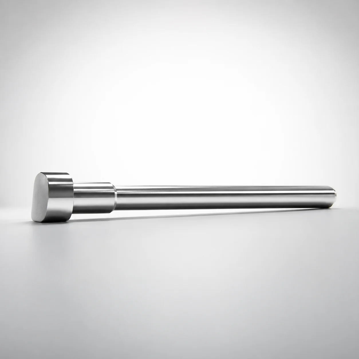
JIS Standard SKH51 Steel D-Shaped Ejector Pins
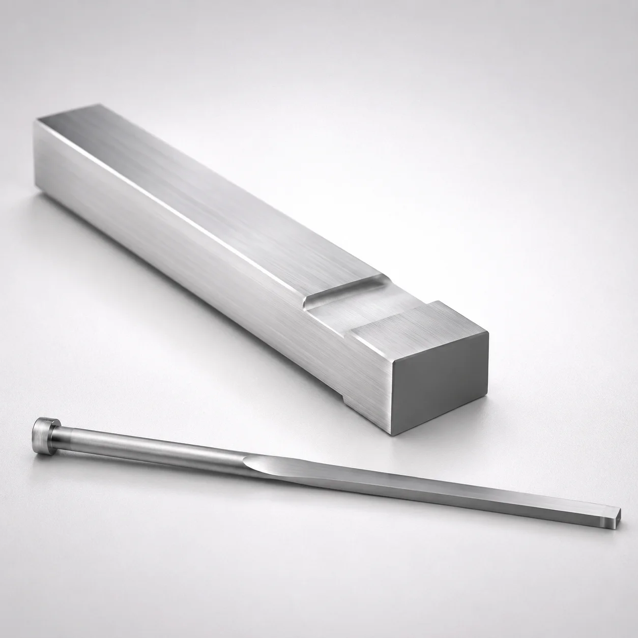
JIS Standard M2 Steel Gas Release Rectangular Ejector Pins
Need Custom Specifications?
Our engineering team can help with custom configurations, material selection, and volume pricing.