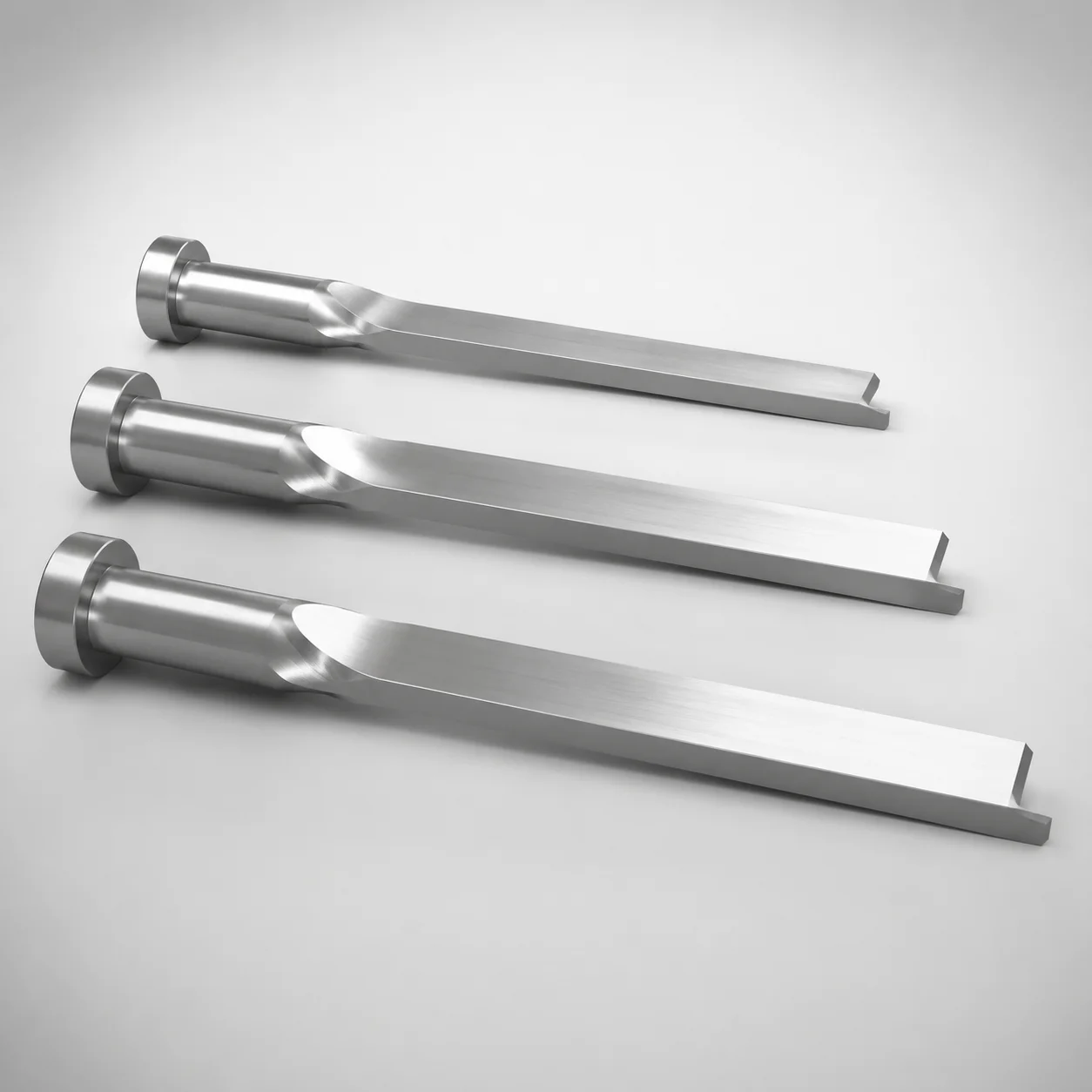
JIS Standard M2 Steel Precision Rectangular Ejector Pins with Tip Processed
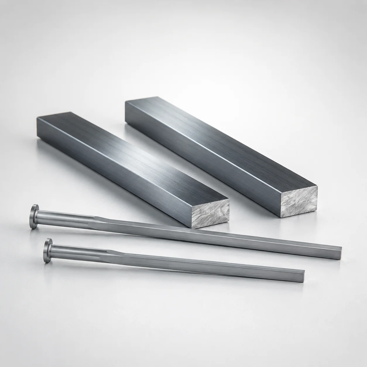
Precision rectangular ejector pins with tip processed (M2 steel) are designed for consistent ejection alignment in precision die and mold applications. The rectangular guidance and processed tip help deliver stable positioning under repeated cycling.
- Rectangular ejector pin body for controlled alignment in the die cavity
- (M2 steel) construction with quenched, hardened wear resistance
- Supports tight assembly by reference to P/W tolerance for stable fit
- Built to JIS specifications for reliable compatibility with standard tooling
Specifications
1092 configurations available
| Head Thickness | P (Tip) (mm) | W (Tip) (mm) | D (Shaft Diameter) (mm) | Tip Shape | R-Chamfered Rectangular Position | L (L dimension) (mm) | Dimension N (mm) | A (mm) | Dimension C (mm) | G (°) | Dimension Q (mm) | Dimension R (mm) | Dimension V (mm) | type |
|---|---|---|---|---|---|---|---|---|---|---|---|---|---|---|
| 4mm(T4) | 0.8 ~ 1.8 | 0.6 ~ 1.72 | 2 | 1X | FR | 50 ~ 250 | 33 ~ 230 | - | - | 1 ~ 45 | - | 0.1 ~ 0.3 | - | - |
| 4mm(T4) | 0.8 ~ 2.3 | 0.6 ~ 2.26 | 2.5 | 1X | FR | 50 ~ 250 | 33 ~ 230 | - | - | 1 ~ 45 | - | 0.1 ~ 0.3 | - | - |
| 4mm(T4) | 0.8 ~ 2.8 | 0.6 ~ 2.8 | 3 | 1X | FR | 50 ~ 300 | 33 ~ 250 | - | - | 1 ~ 45 | - | 0.1 ~ 0.3 | - | - |
| 4mm(T4) | 1 ~ 3.3 | 0.6 ~ 3.3 | 3.5 | 1X | FR | 50 ~ 300 | 33 ~ 250 | - | - | 1 ~ 45 | - | 0.1 ~ 0.3 | - | - |
| 4mm(T4) | 1 ~ 3.8 | 0.6 ~ 3.8 | 4 | 1X | FR | 50 ~ 300 | 33 ~ 250 | - | - | 1 ~ 45 | - | 0.1 ~ 0.3 | - | - |
| 4mm(T4) | 1.2 ~ 4.3 | 0.6 ~ 4.3 | 4.5 | 1X | FR | 50 ~ 300 | 33 ~ 250 | - | - | 1 ~ 45 | - | 0.1 ~ 0.3 | - | - |
| 4mm(T4) | 1.5 ~ 4.8 | 0.6 ~ 4.8 | 5 | 1X | FR | 50 ~ 300 | 33 ~ 250 | - | - | 1 ~ 45 | - | 0.1 ~ 0.3 | - | - |
| 4mm(T4) | 1.5 ~ 5.3 | 0.8 ~ 5.3 | 5.5 | 1X | FR | 50 ~ 300 | 33 ~ 250 | - | - | 1 ~ 45 | - | 0.1 ~ 0.3 | - | - |
| 4mm(T4) | 2 ~ 5.8 | 0.8 ~ 5.8 | 6 | 1X | FR | 50 ~ 300 | 33 ~ 250 | - | - | 1 ~ 45 | - | 0.1 ~ 0.3 | - | - |
| 4mm(T4) | 2 ~ 6.3 | 0.8 ~ 6.3 | 6.5 | 1X | FR | 50 ~ 300 | 40 ~ 250 | - | - | 1 ~ 45 | - | 0.1 ~ 0.3 | - | - |
| 4mm(T4) | 2.3 ~ 6.8 | 0.8 ~ 6.8 | 7 | 1X | FR | 50 ~ 300 | 40 ~ 250 | - | - | 1 ~ 45 | - | 0.1 ~ 0.3 | - | - |
| 4mm(T4) | 2.3 ~ 7.8 | 0.8 ~ 7.8 | 8 | 1X | FR | 50 ~ 300 | 40 ~ 250 | - | - | 1 ~ 45 | - | 0.1 ~ 0.3 | - | - |
| 4mm(T4) | 3 ~ 9.8 | 0.8 ~ 9.8 | 10 | 1X | FR | 50 ~ 300 | 40 ~ 250 | - | - | 1 ~ 45 | - | 0.1 ~ 0.3 | - | - |
| 4mm(T4) | 0.8 ~ 1.8 | 0.6 ~ 1.72 | 2 | 1Y | FR | 50 ~ 250 | 33 ~ 230 | - | - | 1 ~ 45 | - | 0.1 ~ 0.3 | - | - |
| 4mm(T4) | 0.8 ~ 2.3 | 0.6 ~ 2.26 | 2.5 | 1Y | FR | 50 ~ 250 | 33 ~ 230 | - | - | 1 ~ 45 | - | 0.1 ~ 0.3 | - | - |
| 4mm(T4) | 0.8 ~ 2.8 | 0.6 ~ 2.8 | 3 | 1Y | FR | 50 ~ 300 | 33 ~ 250 | - | - | 1 ~ 45 | - | 0.1 ~ 0.3 | - | - |
| 4mm(T4) | 1 ~ 3.3 | 0.6 ~ 3.3 | 3.5 | 1Y | FR | 50 ~ 300 | 33 ~ 250 | - | - | 1 ~ 45 | - | 0.1 ~ 0.3 | - | - |
| 4mm(T4) | 1 ~ 3.8 | 0.6 ~ 3.8 | 4 | 1Y | FR | 50 ~ 300 | 33 ~ 250 | - | - | 1 ~ 45 | - | 0.1 ~ 0.3 | - | - |
| 4mm(T4) | 1.2 ~ 4.3 | 0.6 ~ 4.3 | 4.5 | 1Y | FR | 50 ~ 300 | 33 ~ 250 | - | - | 1 ~ 45 | - | 0.1 ~ 0.3 | - | - |
| 4mm(T4) | 1.5 ~ 4.8 | 0.6 ~ 4.8 | 5 | 1Y | FR | 50 ~ 300 | 33 ~ 250 | - | - | 1 ~ 45 | - | 0.1 ~ 0.3 | - | - |
| 4mm(T4) | 1.5 ~ 5.3 | 0.8 ~ 5.3 | 5.5 | 1Y | FR | 50 ~ 300 | 33 ~ 250 | - | - | 1 ~ 45 | - | 0.1 ~ 0.3 | - | - |
| 4mm(T4) | 2 ~ 5.8 | 0.8 ~ 5.8 | 6 | 1Y | FR | 50 ~ 300 | 33 ~ 250 | - | - | 1 ~ 45 | - | 0.1 ~ 0.3 | - | - |
| 4mm(T4) | 2 ~ 6.3 | 0.8 ~ 6.3 | 6.5 | 1Y | FR | 50 ~ 300 | 40 ~ 250 | - | - | 1 ~ 45 | - | 0.1 ~ 0.3 | - | - |
| 4mm(T4) | 2.3 ~ 6.8 | 0.8 ~ 6.8 | 7 | 1Y | FR | 50 ~ 300 | 40 ~ 250 | - | - | 1 ~ 45 | - | 0.1 ~ 0.3 | - | - |
| 4mm(T4) | 2.3 ~ 7.8 | 0.8 ~ 7.8 | 8 | 1Y | FR | 50 ~ 300 | 40 ~ 250 | - | - | 1 ~ 45 | - | 0.1 ~ 0.3 | - | - |
| 4mm(T4) | 3 ~ 9.8 | 0.8 ~ 9.8 | 10 | 1Y | FR | 50 ~ 300 | 40 ~ 250 | - | - | 1 ~ 45 | - | 0.1 ~ 0.3 | - | - |
| 4mm(T4) | 0.8 ~ 1.8 | 0.6 ~ 1.72 | 2 | 2X | FR | 50 ~ 250 | 33 ~ 230 | - | - | 45 ~ 90 | - | 0.1 ~ 0.3 | 0.3 ~ 1.79 | - |
| 4mm(T4) | 0.8 ~ 2.3 | 0.6 ~ 2.26 | 2.5 | 2X | FR | 50 ~ 250 | 33 ~ 230 | - | - | 45 ~ 90 | - | 0.1 ~ 0.3 | 0.3 ~ 2.29 | - |
| 4mm(T4) | 1 ~ 2.8 | 0.6 ~ 2.72 | 3 | 2X | FR | 50 ~ 300 | 33 ~ 250 | - | - | 45 ~ 90 | - | 0.1 ~ 0.3 | 0.3 ~ 2.79 | - |
| 4mm(T4) | 1 ~ 3.3 | 0.6 ~ 3.24 | 3.5 | 2X | FR | 50 ~ 300 | 33 ~ 250 | - | - | 45 ~ 90 | - | 0.1 ~ 0.3 | 0.3 ~ 3.29 | - |
| 4mm(T4) | 1 ~ 3.8 | 0.6 ~ 3.76 | 4 | 2X | FR | 50 ~ 300 | 33 ~ 250 | - | - | 45 ~ 90 | - | 0.1 ~ 0.3 | 0.3 ~ 3.79 | - |
| 4mm(T4) | 1.2 ~ 4.3 | 0.6 ~ 4.23 | 4.5 | 2X | FR | 50 ~ 300 | 33 ~ 250 | - | - | 45 ~ 90 | - | 0.1 ~ 0.3 | 0.3 ~ 4.29 | - |
| 4mm(T4) | 1.5 ~ 4.8 | 0.6 ~ 4.66 | 5 | 2X | FR | 50 ~ 300 | 33 ~ 250 | - | - | 45 ~ 90 | - | 0.1 ~ 0.3 | 0.3 ~ 4.79 | - |
| 4mm(T4) | 1.8 ~ 5.3 | 0.8 ~ 5.09 | 5.5 | 2X | FR | 50 ~ 300 | 33 ~ 250 | - | - | 45 ~ 90 | - | 0.1 ~ 0.3 | 0.3 ~ 5.29 | - |
| 4mm(T4) | 2 ~ 5.8 | 0.8 ~ 5.55 | 6 | 2X | FR | 50 ~ 300 | 33 ~ 250 | - | - | 45 ~ 90 | - | 0.1 ~ 0.3 | 0.3 ~ 5.79 | - |
| 4mm(T4) | 2 ~ 6.3 | 0.8 ~ 6.07 | 6.5 | 2X | FR | 50 ~ 300 | 40 ~ 250 | - | - | 45 ~ 90 | - | 0.1 ~ 0.3 | 0.3 ~ 6.29 | - |
| 4mm(T4) | 2.3 ~ 6.8 | 0.8 ~ 6.5 | 7 | 2X | FR | 50 ~ 300 | 40 ~ 250 | - | - | 45 ~ 90 | - | 0.1 ~ 0.3 | 0.3 ~ 6.79 | - |
| 4mm(T4) | 2.3 ~ 7.8 | 0.8 ~ 7.55 | 8 | 2X | FR | 50 ~ 300 | 40 ~ 250 | - | - | 45 ~ 90 | - | 0.1 ~ 0.3 | 0.3 ~ 7.79 | - |
| 4mm(T4) | 3 ~ 9.8 | 0.8 ~ 9.43 | 10 | 2X | FR | 50 ~ 300 | 40 ~ 250 | - | - | 45 ~ 90 | - | 0.1 ~ 0.3 | 0.3 ~ 9.79 | - |
| 4mm(T4) | 0.8 ~ 1.8 | 0.6 ~ 1.72 | 2 | 2Y | FR | 50 ~ 250 | 33 ~ 230 | - | - | 45 ~ 90 | - | 0.1 ~ 0.3 | 0.3 ~ 1.71 | - |
| 4mm(T4) | 0.8 ~ 2.3 | 0.6 ~ 2.26 | 2.5 | 2Y | FR | 50 ~ 250 | 33 ~ 230 | - | - | 45 ~ 90 | - | 0.1 ~ 0.3 | 0.3 ~ 2.25 | - |
| 4mm(T4) | 1 ~ 2.8 | 0.6 ~ 2.72 | 3 | 2Y | FR | 50 ~ 300 | 33 ~ 250 | - | - | 45 ~ 90 | - | 0.1 ~ 0.3 | 0.3 ~ 2.71 | - |
| 4mm(T4) | 1 ~ 3.3 | 0.6 ~ 3.24 | 3.5 | 2Y | FR | 50 ~ 300 | 33 ~ 250 | - | - | 45 ~ 90 | - | 0.1 ~ 0.3 | 0.3 ~ 3.23 | - |
| 4mm(T4) | 1 ~ 3.8 | 0.6 ~ 3.76 | 4 | 2Y | FR | 50 ~ 300 | 33 ~ 250 | - | - | 45 ~ 90 | - | 0.1 ~ 0.3 | 0.3 ~ 3.75 | - |
| 4mm(T4) | 1.2 ~ 4.3 | 0.6 ~ 4.23 | 4.5 | 2Y | FR | 50 ~ 300 | 33 ~ 250 | - | - | 45 ~ 90 | - | 0.1 ~ 0.3 | 0.3 ~ 4.22 | - |
| 4mm(T4) | 1.5 ~ 4.8 | 0.6 ~ 4.66 | 5 | 2Y | FR | 50 ~ 300 | 33 ~ 250 | - | - | 45 ~ 90 | - | 0.1 ~ 0.3 | 0.3 ~ 4.65 | - |
| 4mm(T4) | 1.8 ~ 5.3 | 0.8 ~ 5.09 | 5.5 | 2Y | FR | 50 ~ 300 | 33 ~ 250 | - | - | 45 ~ 90 | - | 0.1 ~ 0.3 | 0.3 ~ 5.08 | - |
| 4mm(T4) | 2 ~ 5.8 | 0.8 ~ 5.55 | 6 | 2Y | FR | 50 ~ 300 | 33 ~ 250 | - | - | 45 ~ 90 | - | 0.1 ~ 0.3 | 0.3 ~ 5.54 | - |
| 4mm(T4) | 2 ~ 6.3 | 0.8 ~ 6.07 | 6.5 | 2Y | FR | 50 ~ 300 | 40 ~ 250 | - | - | 45 ~ 90 | - | 0.1 ~ 0.3 | 0.3 ~ 6.06 | - |
| 4mm(T4) | 2.3 ~ 6.8 | 0.8 ~ 6.5 | 7 | 2Y | FR | 50 ~ 300 | 40 ~ 250 | - | - | 45 ~ 90 | - | 0.1 ~ 0.3 | 0.3 ~ 6.49 | - |
Product Guide
Application Scenarios+
These JIS-compliant precision ejector pins are used in injection mold and die tooling where stable ejection alignment is critical. The rectangular guide geometry helps resist lateral wobble during repeated cycling, improving knockout repeatability in high-precision cavities.
- Automotive and appliance connectors: In molds for multi-part connectors and housings, the processed pin tip and rectangular body support consistent alignment, reducing risk of flash or uneven part release.
- Thin-wall electronics housings: For small, tightly guided components, selecting this M2-based pin helps maintain controlled motion under load while keeping guidance stable through the ejection stroke.
- Progressive die tooling: Rectangular ejector guidance is suited to die stations that demand reliable positioning and smooth transfer, especially when the tip geometry (0.8–3 mm) is tuned to the part contact area.
The M2 steel variant with tip processing is specifically suited for these scenarios because it balances guidance stability with wear resistance for long production runs.
Material & Process Details+
This product uses JIS M2 steel with a hardened, wear-resistant condition. M2 is commonly used for cutting and high-wear tooling applications, providing a good balance of hardness and toughness for ejector components that experience repetitive sliding and contact.
- Wear resistance: Hardened M2 improves resistance to abrasion at the processed tip and guided surfaces.
- Hardness: The description specifies a quenched, hardened wear resistance state, supporting stable performance under cyclic ejection loading. (Exact HRC is not provided in the input data.)
- Toughness trade-off: Higher hardness increases wear resistance but can reduce impact tolerance if misaligned loads occur—rectangular guidance helps mitigate this.
If alternative pin steels are considered, hardened wear-focused grades typically offer better abrasion resistance than lower-alloy, but designers must verify hardness and toughness balance for the expected ejection forces.
Sizing & Selection Guide+
Select dimensions by matching the ejector contact and guidance requirements of the cavity/core assembly. Start with the shaft diameter (D), available from 2–10 mm, to ensure proper clearance and fit within the guiding holes of the mold.
- Tip geometry: Choose the tip (P) from 0.8–3 mm and tip width (W) from 0.6–0.8 mm to match the part release area and avoid over-contact.
- Length (L / L dimension): Use L = 50–250 mm (or 50–300 mm depending on the configuration) and confirm the required stroke length to cover the ejection travel without bottoming.
- Reference geometry: For the rectangular positioning, use the specified chamfer/radius option (FR, Qr, WR) and respect the fixed R = 0.1–0.3 mm and variable A (0–0.3 mm), C (0.5–5 mm / 0.3–5 mm / 0.3–5 mm) and Q (0.5–3.6 mm).
For tight assembly, the description references P/W tolerance to support stable fit; verify your mold housing bore tolerance and ensure guidance alignment to prevent side loading during ejection. Tip shape can be selected via Tip Shape = 1–7.
Frequently Asked Questions
Which shaft diameter (D) range should I select for the guiding hole in my mold core?+
For this precision rectangular ejector pin, the shaft diameter (D) is available in the 2–10 mm range. Choose the D value that matches the guiding hole geometry and required clearance/fit in your ejector plate and core structure. If you experience lateral play, re-check both the bore size tolerance and the rectangular guidance reference surfaces.
How do I choose the tip dimensions (P and W) to control the ejection contact area?+
The tip (P) is specified as 0.8–3 mm and the tip width (W) is 0.6–0.8 mm. Select P and W based on the part’s release pocket/contact surface so the pin engages reliably without excessive pressure that can cause part surface damage or flash. Keep the selected configuration consistent with the P/W tolerance guidance referenced for stable fit.
What length options (L) are available for different ejection stroke requirements?+
The L (L dimension) is available from 50–250 mm and also up to 50–300 mm depending on configuration. Use the available length that covers the required ejection stroke while preventing bottoming against the end stop surfaces. Confirm your build height and ejector plate offsets before finalizing the pin length.
What does “tip processed” and the fixed R dimension imply for guiding and wear?+
This variant is described as having a processed tip to support stable rectangular guidance during repeated cycling. The spec also includes a fixed R = 0.1–0.3 mm, which affects the edge/radius at the transition area. Together, the processed tip geometry and the radius help manage contact behavior and can improve wear consistency under cyclic ejection.
How should I account for rectangular positioning options (FR/Qr/WR) when designing the corresponding slot or pocket?+
The rectangular position includes selectable chamfer/radius configuration options: FR, Qr, WR. When designing the mating feature in the mold, ensure the selected configuration is aligned with your assembly’s reference surfaces so the pin guidance remains stable. Because A (0–0.3 mm), C (up to 0.5–5 / 0.3–5 mm ranges), and Q (0.5–3.6 mm) vary by configuration, verify the full dimension set rather than assuming a single geometry.
Related Products
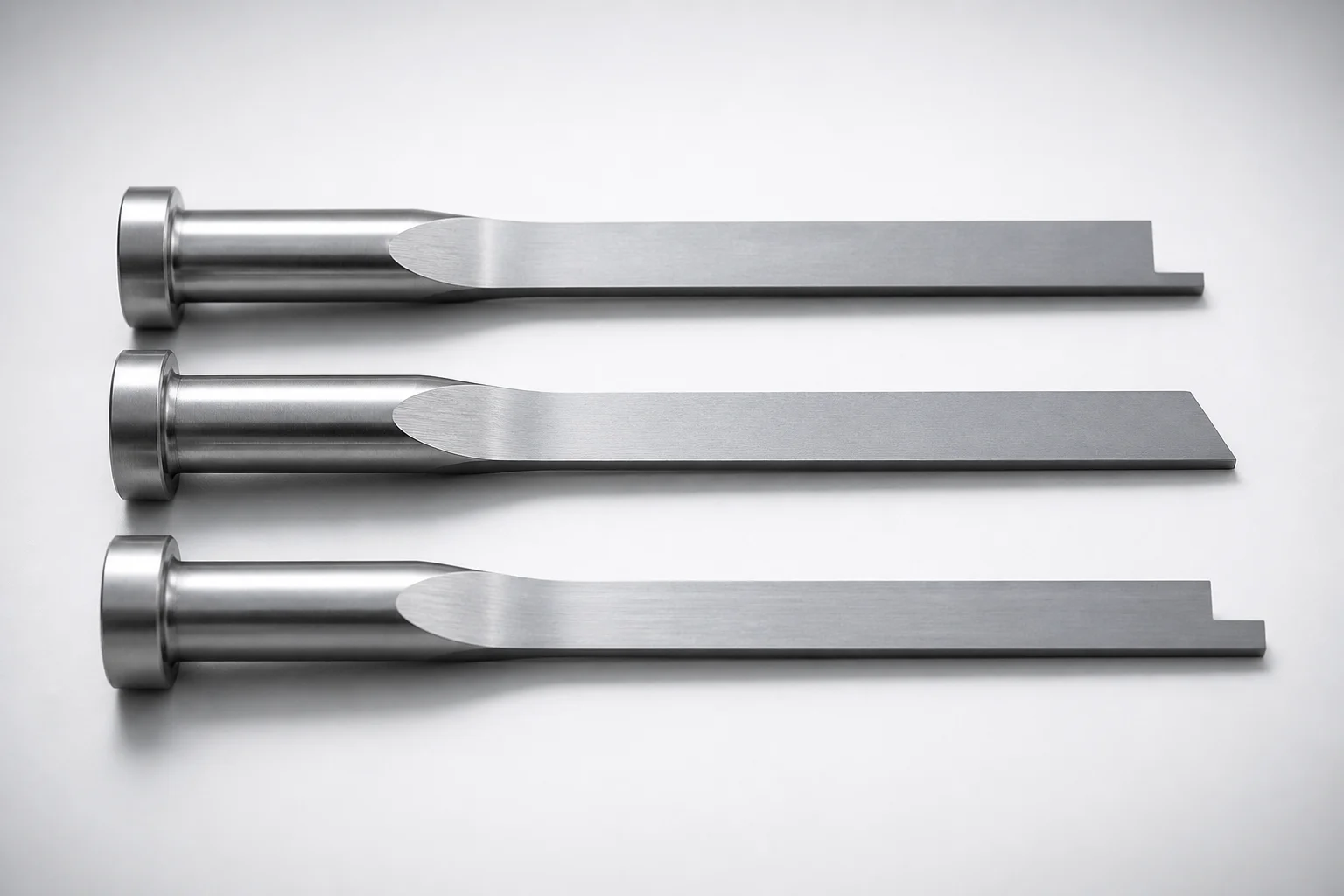
JIS Standard SKH51 Steel Precision Rectangular Ejector Pins with Tip Processed
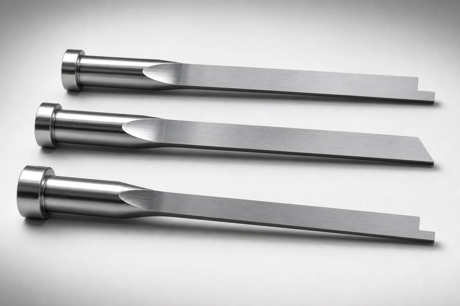
JIS Standard SKH51 Steel Tip-Processed Rectangular Ejector Pins
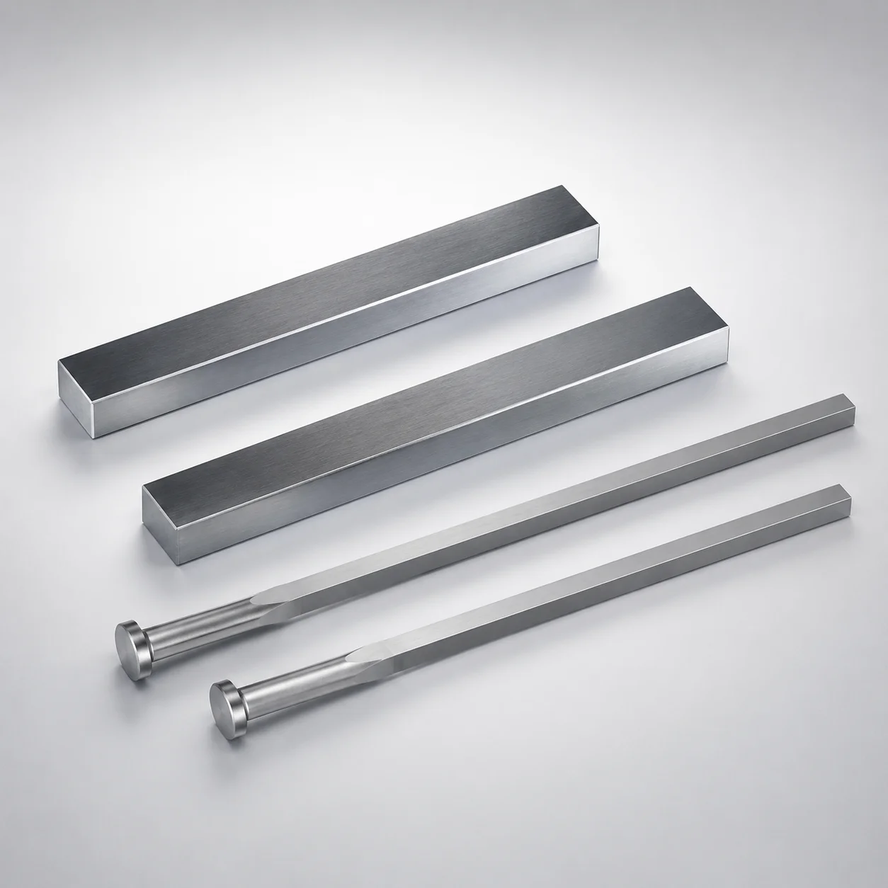
JIS Standard SKH51 Steel Rectangular Ejector Pins with Engraving
M2 Steel Rectangular Ejector Pins with Engraving - Flat-Head
JIS Standard SKH51 Steel D-Shaped Ejector Pins
JIS Standard M2 Steel Gas Release Rectangular Ejector Pins
Need Custom Specifications?
Our engineering team can help with custom configurations, material selection, and volume pricing.