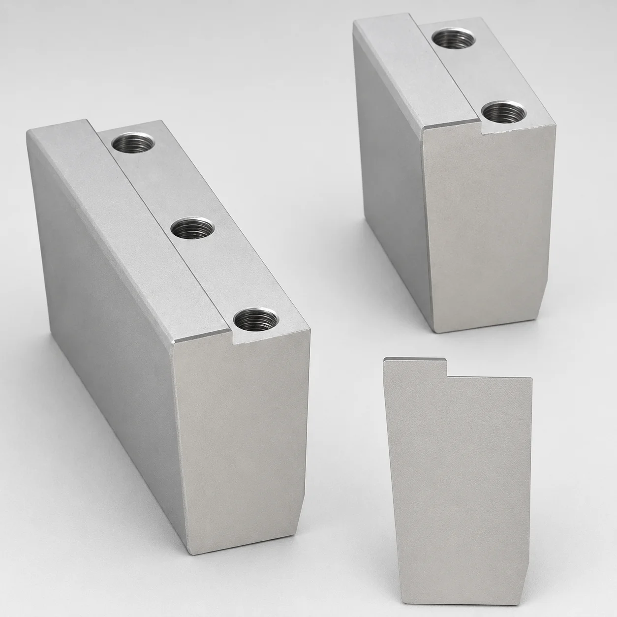
O1 Tool Steel Positioning Locking Blocks - Beveled Edge Bottom (KN)
Positioning locking blocks (O1 tool steel) with a KN beveled edge bottom provide reliable positioning for PL installation, while allowing angle flexibility to match your locating requirements.
- Beveled edge bottom (KN) supports consistent contact and improved positional stability
- O1 tool steel construction with wear-resistant performance for long production runs
- Configurable locking angles help optimize fit for different locating geometries
- Non-oil groove option suitable when lubrication control is not required
Specifications
4 configurations available
| Block Height T (mm) | Block Length L (mm) | A/W (Block width) (mm) | K (Locking Angle) (°) | G (Angle) (°) | No processing for beveled bottom | type |
|---|---|---|---|---|---|---|
| 30 ~ 45 | 25 | 38 ~ 98 | 5 | 5 ~ 20 | - | - |
| 30 ~ 45 | 25 | 38 ~ 98 | - | 5 ~ 20 | KN | - |
| 45 | 40 | 68 ~ 108 | 5 ~ 10 | 5 ~ 22 | - | - |
| 45 | 40 | 68 ~ 108 | - | 5 ~ 22 | KN | - |
Product Guide
Application Scenarios+
These O1 tool steel positioning locking blocks are used in injection mold tooling wherever precise, repeatable locating is needed for undercut/plate style assemblies. The KN beveled edge bottom helps create consistent contact during clamp-up, improving positional stability for parts that must remain aligned over many cycles.
- Automotive connector and housing molds: commonly used for plate and insert positioning so mating components maintain correct register under vibration and thermal expansion.
- Consumer and appliance enclosure tooling: supports stable PL installation with adjustable locking angle ranges to match different locating features and reduce misalignment risk during setup.
- Industrial tooling for long-run production: O1 tool steel provides wear-resistant performance for durable locating surfaces, reducing wear-driven drift in high cycle environments.
The angle configurable feature (K and G ranges) makes this variant suited for matching diverse locating geometries, while the fixed KN beveled bottom provides reliable edge contact without requiring additional processing.
Material & Process Details+
This block is made from O1 tool steel, a high-carbon oil-hardening tool steel typically selected for tooling parts that need good wear resistance and stable machining characteristics. In service, O1 balances hardness for long life at the contact area with toughness to better tolerate minor shock loads during mold actuation.
- Wear vs. toughness trade-off: higher achievable hardness improves wear resistance at the locking interface but can reduce impact toughness if over-hardened.
- Heat treatment: O1 is commonly quenched and tempered after machining to reach target hardness and dimensional stability for the locating surfaces.
- Surface/edge performance: the KN beveled edge bottom area benefits from the hardened locating surface condition to resist fretting and micro-wear.
Compared with more alloyed wear-first steels, O1 often offers a favorable balance of machinability and performance for positioning components, especially when heat treatment is tuned for hardness and toughness.
Sizing & Selection Guide+
Select the block dimensions by matching the locating requirements of your PL installation and the mating components in the undercuts/plates stack-up. The series specifies variable ranges for block height T (30–45 mm, including 45 mm), block length L (25 or 40 mm), and block width A/W (38–98 mm, including 68–108 mm depending on configuration).
- Step 1 (Height T): choose T to align the locating elevation with the target plate/core register so the beveled bottom sits correctly under clamp load.
- Step 2 (Plan dimensions L and A/W): ensure L and A/W fit within your plate space and allow clearance for assembly and any adjacent hardware.
- Step 3 (Angle matching): select the locking angle K (5° or 5–10°) and angle G (5–20° or 5–22°) that best matches your locating geometry.
- Tolerance/fit: while exact tolerances are not provided, plan for standard mold assembly fit by verifying contact area and ensuring the KN beveled edge achieves consistent contact.
The beveled bottom is fixed as KN with no processing required, so dimensioning should focus on T, L, A/W, and the chosen angle set.
Frequently Asked Questions
How do I choose the correct locking angle K (5° or 5–10°) for stable PL installation?+
Use the K range (5° or 5–10°) to match the mating plate locating geometry and the intended locking engagement. Pair it with the compatible G angle option available in your configuration (5–20° or 5–22°) to ensure the bevel contacts as designed. If your locating feature has tighter angular conformity, select the narrower K range to improve repeatability.
What block heights T are available, and how should T be matched to the mold stack-up?+
The available T values are 30–45 mm, including a specific 45 mm option. Match T to the required elevation for PL installation so the KN beveled bottom seats consistently under clamp force. Confirm that the chosen T does not interfere with adjacent plates, screws, or undercut features in the stack-up.
Is KN beveled bottom processing required, and what does the fixed KN design mean for machining plans?+
The spec indicates no processing for beveled bottom and the bottom is fixed as KN. This means your machining plan should not rely on altering the bevel geometry. Focus on selecting the correct T, L, A/W, and angle set so the fixed KN bevel provides consistent contact.
Which width A/W ranges should I consider when designing for available space on the plate?+
The block width A/W is provided in two ranges: 38–98 mm and 68–108 mm depending on the selected configuration. Use these ranges to fit within your plate envelope and maintain sufficient clearance to adjacent components. Verify that the contact region formed by the KN bevel aligns with the locating surface.
Can this O1 tool steel locating block be used without lubrication grooves (non-oil groove option)?+
The current product description states a non-oil groove option is available when lubrication control is not required. For applications where you manage lubrication elsewhere or aim to avoid groove contamination, this option can simplify the interface design. Confirm your maintenance and expected wear environment before committing to the non-oil configuration.
Related Products
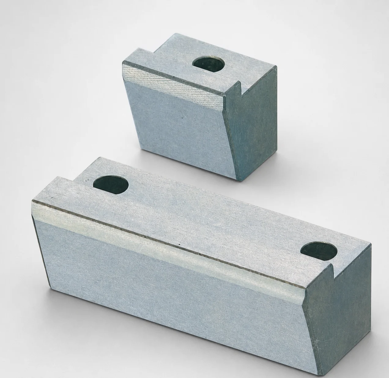
O1 Tool Steel Positioning Locking Blocks with Oil Grooves
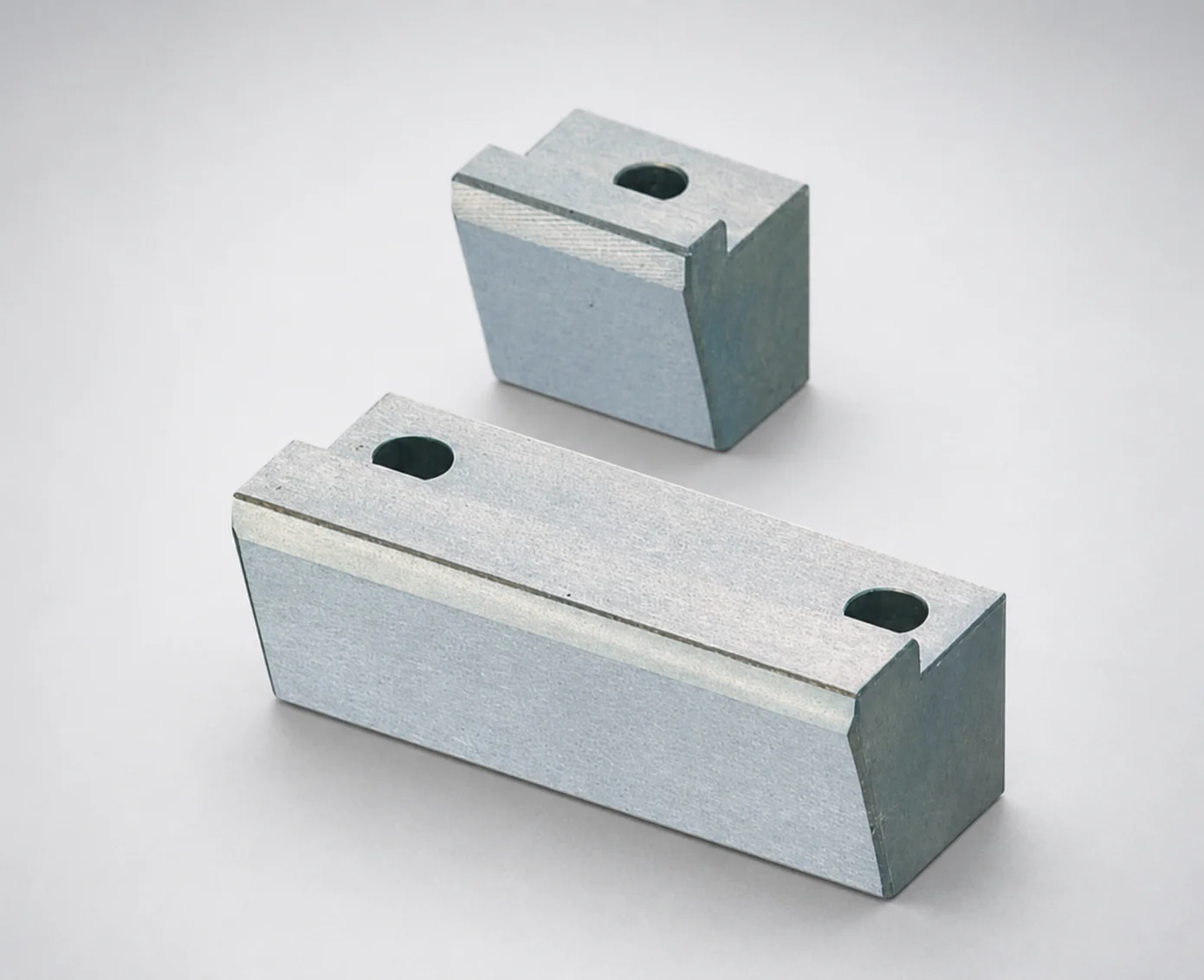
Positioning Locking Blocks Angle Configurable, Oil-Free Options
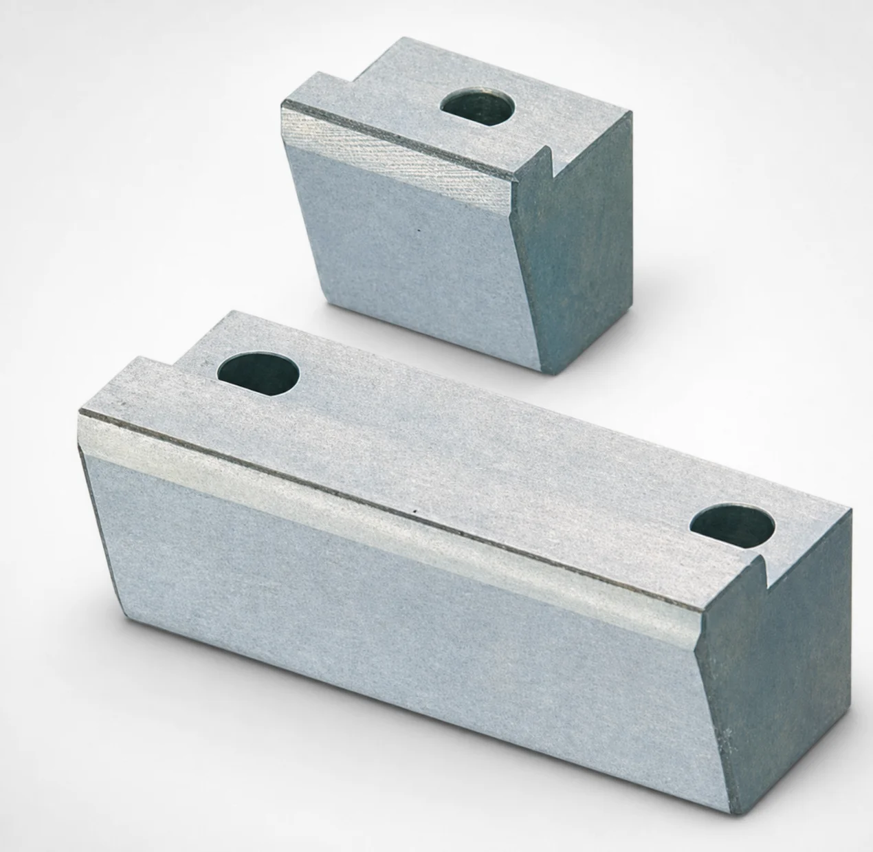
O1 Tool Steel Positioning Locking Blocks - Angle Configurable
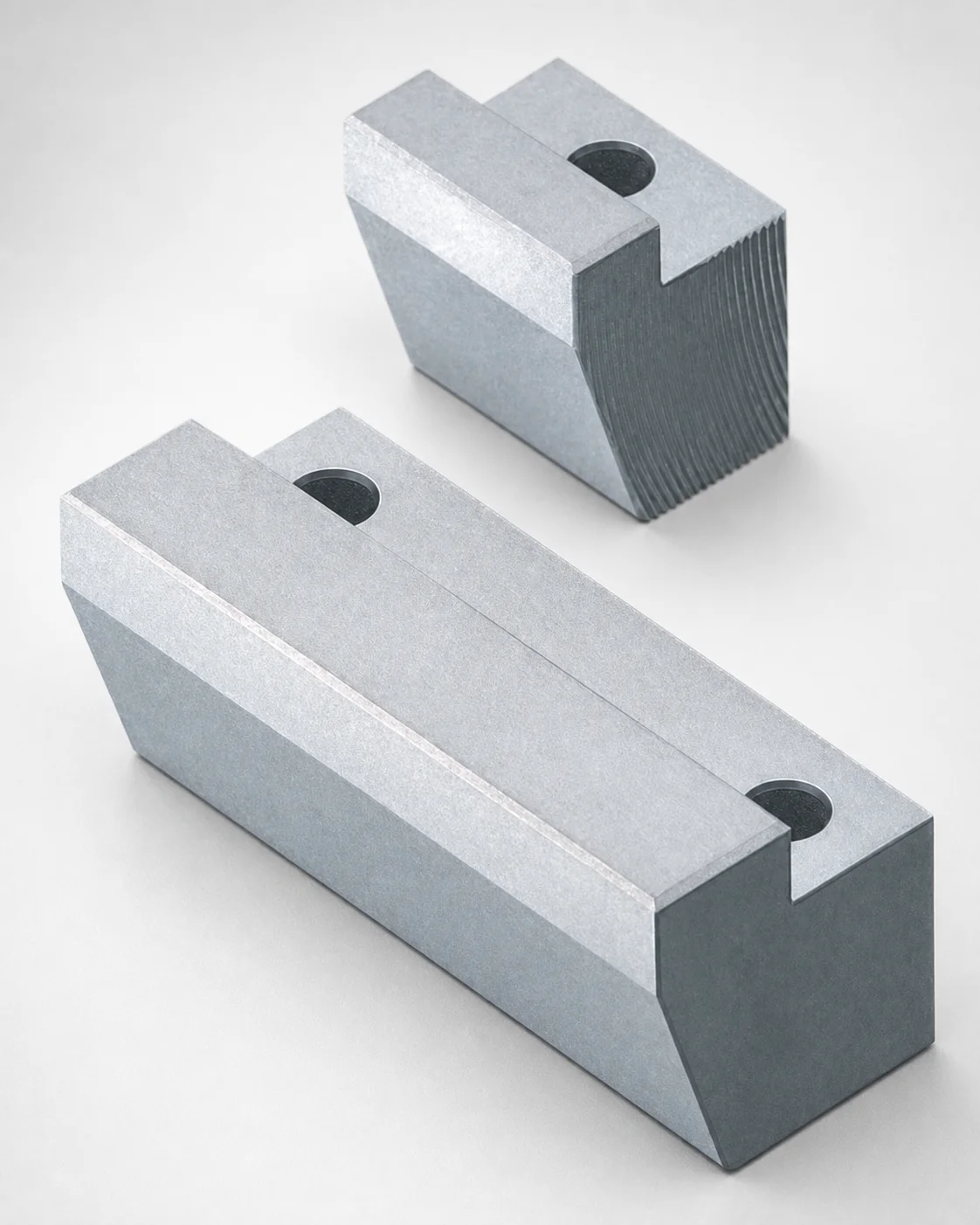
Locking Blocks - Fixed Angle & Inlay Height Configurable
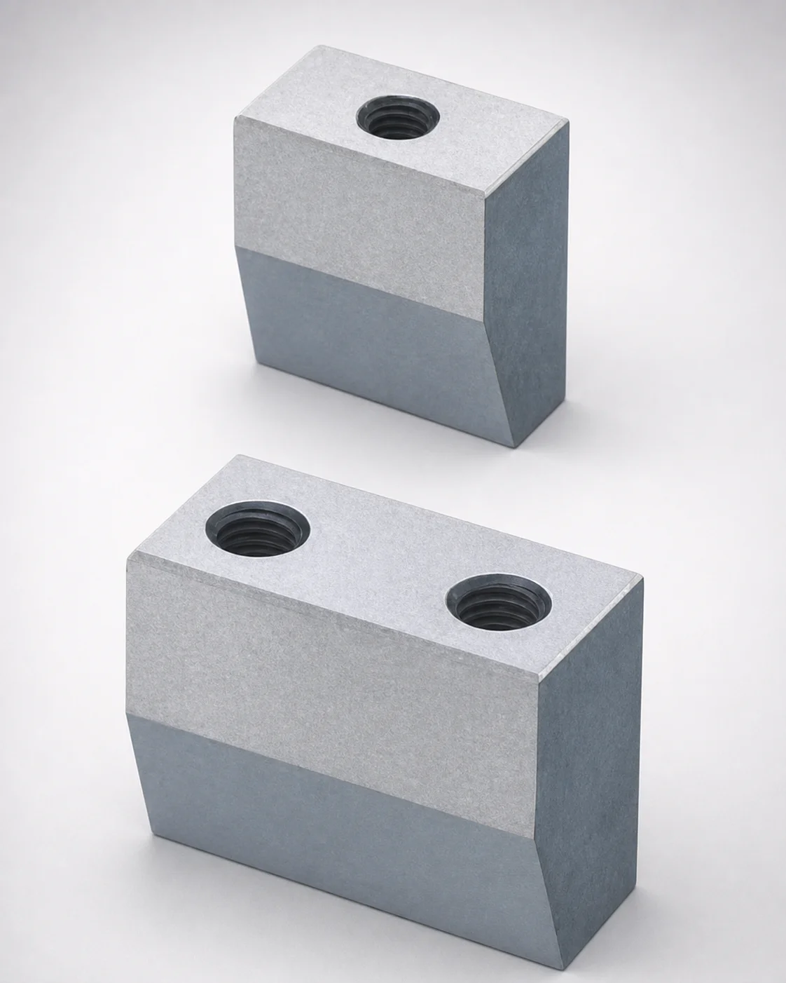
Inlay Type Locking Blocks with Plate Side Setting (Tapped)
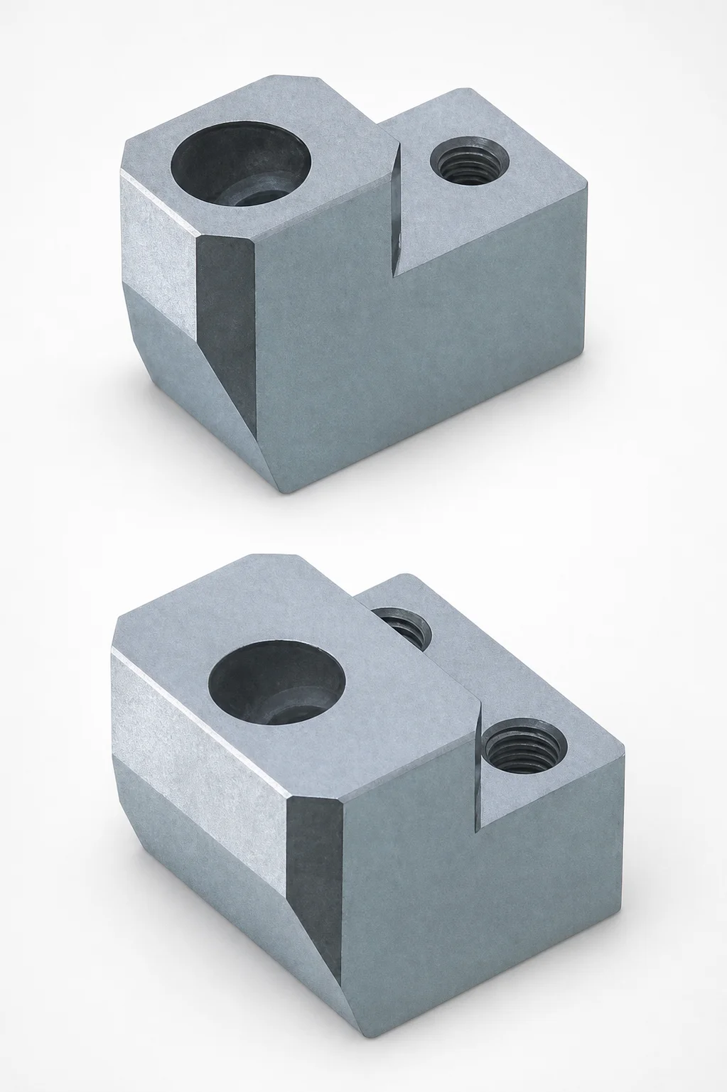
ABPXE Type O1 Tool Steel Positioning Locking Blocks with Angular Pin Hole
Need Custom Specifications?
Our engineering team can help with custom configurations, material selection, and volume pricing.