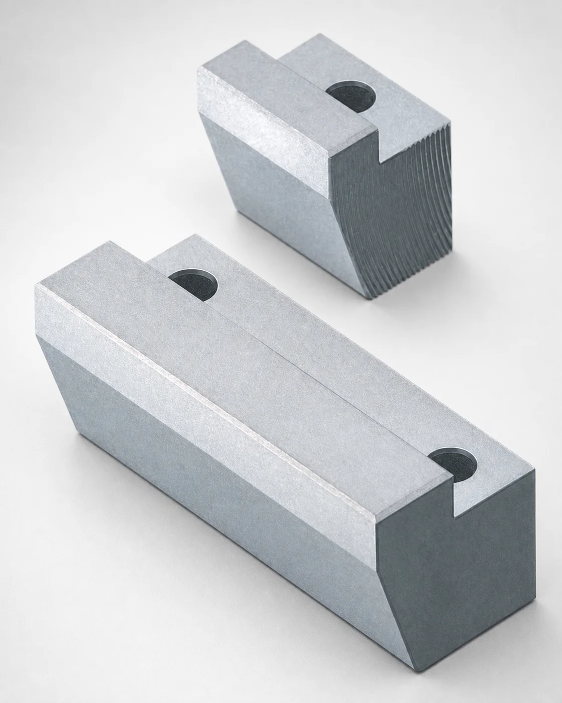
Locking Blocks - Fixed Angle & Inlay Height Configurable
Locking Blocks - Fixed Angle & Inlay Height Configurable are positioning-type blocks designed for PL bolt fixing. With an oil-free groove option and a set locking angle, they help maintain repeatable location in mold and fixture assemblies.
- Fixed locking angle (0°) for stable anti-shift positioning
- Configurable inlay height to match different plate or component layouts
- Oil groove: non-oil option reduces contamination risk during operation
- Suitable for tooling setups requiring secure locking in production molds
Specifications
51 configurations available
| Material | Block Height T (mm) | Block Length L (mm) | A/W (Block width) (mm) | H/E (Inlay Part Dimension) (mm) | G (Angle) (°) | type |
|---|---|---|---|---|---|---|
| SKD61 | 15 | 20 | 13 ~ 60 | 3 ~ 8 | 5 ~ 24 | - |
| SKD61 | 20 | 20 | 13 ~ 60 | 3 ~ 8 | 5 ~ 18 | - |
| SKD61 | 20 | 25 | 18 ~ 100 | 3 ~ 8 | 5 ~ 26 | - |
| SKD61 | 15 | 30 | 23 ~ 130 | 3 ~ 10 | 5 ~ 33 | - |
| SKD61 | 20 | 30 | 23 ~ 130 | 3 ~ 10 | 5 ~ 33 | - |
| SKD61 | 25 | 30 | 23 ~ 130 | 3 ~ 10 | 5 ~ 28 | - |
| SKD61 | 30 | 30 | 23 ~ 130 | 3 ~ 10 | 5 ~ 25 | - |
| SKD61 | 25 | 35 | 38 ~ 150 | 3 ~ 15 | 5 ~ 33 | - |
| SKD61 | 30 | 35 | 38 ~ 150 | 3 ~ 15 | 5 ~ 28 | - |
| SKD61 | 35 | 35 | 38 ~ 150 | 3 ~ 15 | 5 ~ 25 | - |
| SKD61 | 40 | 35 | 38 ~ 150 | 3 ~ 15 | 5 ~ 22 | - |
| SKD61 | 30 | 40 | 48 ~ 150 | 3 ~ 15 | 5 ~ 32 | - |
| SKD61 | 35 | 40 | 48 ~ 150 | 3 ~ 15 | 5 ~ 28 | - |
| SKD61 | 40 | 40 | 48 ~ 150 | 3 ~ 15 | 5 ~ 25 | - |
| SKD61 | 45 | 40 | 48 ~ 150 | 3 ~ 15 | 5 ~ 22 | - |
| SKD61 | 40 | 50 | 68 ~ 200 | 3 ~ 15 | 5 ~ 31 | - |
| SKD61 | 45 | 50 | 68 ~ 200 | 3 ~ 15 | 5 ~ 28 | - |
| HPM2T | 15 | 20 | 13 ~ 60 | 3 ~ 8 | 5 ~ 24 | - |
| HPM2T | 20 | 20 | 13 ~ 60 | 3 ~ 8 | 5 ~ 18 | - |
| HPM2T | 20 | 25 | 18 ~ 100 | 3 ~ 8 | 5 ~ 26 | - |
| HPM2T | 15 | 30 | 23 ~ 130 | 3 ~ 10 | 5 ~ 33 | - |
| HPM2T | 20 | 30 | 23 ~ 130 | 3 ~ 10 | 5 ~ 33 | - |
| HPM2T | 25 | 30 | 23 ~ 130 | 3 ~ 10 | 5 ~ 28 | - |
| HPM2T | 30 | 30 | 23 ~ 130 | 3 ~ 10 | 5 ~ 25 | - |
| HPM2T | 25 | 35 | 38 ~ 150 | 3 ~ 15 | 5 ~ 33 | - |
| HPM2T | 30 | 35 | 38 ~ 150 | 3 ~ 15 | 5 ~ 28 | - |
| HPM2T | 35 | 35 | 38 ~ 150 | 3 ~ 15 | 5 ~ 25 | - |
| HPM2T | 40 | 35 | 38 ~ 150 | 3 ~ 15 | 5 ~ 22 | - |
| HPM2T | 30 | 40 | 48 ~ 150 | 3 ~ 15 | 5 ~ 32 | - |
| HPM2T | 35 | 40 | 48 ~ 150 | 3 ~ 15 | 5 ~ 28 | - |
| HPM2T | 40 | 40 | 48 ~ 150 | 3 ~ 15 | 5 ~ 25 | - |
| HPM2T | 45 | 40 | 48 ~ 150 | 3 ~ 15 | 5 ~ 22 | - |
| HPM2T | 40 | 50 | 68 ~ 200 | 3 ~ 15 | 5 ~ 31 | - |
| HPM2T | 45 | 50 | 68 ~ 200 | 3 ~ 15 | 5 ~ 28 | - |
| O1 Tool Steel | 15 | 20 | 13 ~ 60 | 3 ~ 8 | 5 ~ 24 | - |
| O1 Tool Steel | 20 | 20 | 13 ~ 60 | 4 ~ 8 | 5 ~ 18 | - |
| O1 Tool Steel | 20 | 25 | 18 ~ 100 | 3 ~ 8 | 5 ~ 26 | - |
| O1 Tool Steel | 15 | 30 | 23 ~ 130 | 3 ~ 10 | 5 ~ 33 | - |
| O1 Tool Steel | 20 | 30 | 23 ~ 130 | 3 ~ 10 | 5 ~ 33 | - |
| O1 Tool Steel | 25 | 30 | 23 ~ 130 | 3 ~ 10 | 5 ~ 28 | - |
| O1 Tool Steel | 30 | 30 | 23 ~ 130 | 3 ~ 10 | 5 ~ 25 | - |
| O1 Tool Steel | 25 | 35 | 38 ~ 150 | 3 ~ 15 | 5 ~ 33 | - |
| O1 Tool Steel | 30 | 35 | 38 ~ 150 | 3 ~ 15 | 5 ~ 28 | - |
| O1 Tool Steel | 35 | 35 | 38 ~ 150 | 3 ~ 15 | 5 ~ 25 | - |
| O1 Tool Steel | 40 | 35 | 38 ~ 150 | 3 ~ 15 | 5 ~ 22 | - |
| O1 Tool Steel | 30 | 40 | 48 ~ 150 | 3 ~ 15 | 5 ~ 32 | - |
| O1 Tool Steel | 35 | 40 | 48 ~ 150 | 3 ~ 15 | 5 ~ 28 | - |
| O1 Tool Steel | 40 | 40 | 48 ~ 150 | 3 ~ 15 | 5 ~ 25 | - |
| O1 Tool Steel | 45 | 40 | 48 ~ 150 | 3 ~ 15 | 5 ~ 22 | - |
| O1 Tool Steel | 40 | 50 | 68 ~ 200 | 3 ~ 15 | 5 ~ 31 | - |
Product Guide
Application Scenarios+
These locking blocks are used in injection mold and fixture assemblies where a repeatable, non-slip location for PL bolt fixing is required. The fixed locking angle (set at 0° per the configuration) supports stable anti-shift positioning during clamp and cycle motions.
In automotive connector and small electrical housing molds, the configurable inlay height helps match the block to different plate thicknesses and groove depths, maintaining consistent alignment for slides, plates, or backing components. The oil-free groove option helps reduce contamination risk in environments that are sensitive to oil migration or debris accumulation.
For precision appliance or industrial component tooling, engineers can select the inlay part dimension range to ensure a tight fit against the mating plate features, improving positioning repeatability between maintenance intervals. With multiple length and width options, the blocks can be integrated into different mold base layouts while retaining secure PL fastening.
Material & Process Details+
Available materials include SKD61, HPM2T, and O1 tool steel, each chosen to balance wear resistance and toughness for different tooling duty cycles. SKD61 is commonly used as an H13-class hot-work mold steel in moldmaking due to its hardenability and performance under thermal cycling. HPM2T is typically selected for improved wear resistance and dimensional stability in cutting/forming-related tooling contexts. O1 is an oil-hardening tool steel option when cost and machinability are prioritized for lighter loads.
- Hardness: Hardened steels are typically specified in the ~HRC range appropriate to their role; exact HRC is not provided for this SKU, so confirm with your heat-treatment plan.
- Heat treatment: Expect a quench-and-temper route for SKD61/HPM2T/O1 to reach working hardness, with trade-offs between maximum hardness (better wear) and toughness (better resistance to edge chipping).
- Wear vs toughness: Higher wear resistance grades can trade off impact toughness; choose based on cyclic loads and expected abrasion.
Sizing & Selection Guide+
Select the locking block size by matching the block height T (15–45 mm), length L (20, 25, 30, 35, 40, 50 mm), and block width A/W to the available space and the mating plate feature envelope. The product supports multiple width bands (e.g., 13–60, 18–100, 23–130, 38–150, 48–150, 68–200 mm), so verify the required width on the mold base or clamping fixture layout.
Next, configure the inlay part dimension H/E using the available ranges (3–8, 3–10, 3–15, or 4–8 mm) to align the inlay depth with the mating PL installation geometry. The locking angle is fixed at G = 5° per the specification, so ensure the mating pocket/feature has the corresponding angle clearance.
- Fit/tolerance: Confirm working clearances between block and the plate recess; tightening forces for PL bolting can magnify any mismatch.
- Configurable vs fixed: Material and inlay height are configurable via the provided ranges; length and height must be selected from the listed options.
Frequently Asked Questions
Which material option (SKD61, HPM2T, or O1) is best for locking blocks under repeated mold cycling?+
This SKU is offered in SKD61, HPM2T, and O1 tool steel. For tooling that sees frequent temperature cycling and long service, SKD61 is commonly selected because of its mold-steel performance under thermal load. For different abrasion and stability requirements, HPM2T may be chosen, while O1 is typically used when prioritizing cost and machinability for lighter-duty conditions.
How do I choose block height T and inlay dimension H/E so the PL installation matches my plate layout?+
Use T (15–45 mm) to match your available installation height in the mold base or fixture. Then select H/E from the supported inlay ranges (3–8, 3–10, 3–15, or 4–8 mm) to fit the mating plate pocket/inlay depth.
What width range A/W and length L should I verify against my mold base space before ordering?+
Confirm the installation envelope for L using the available options (20, 25, 30, 35, 40, 50 mm). For width, choose a configuration within the supported A/W ranges (e.g., 13–60 up to 68–200 mm, depending on the option set).
Is the locking angle truly fixed, and what angle value should I model in my mating feature?+
The configuration provides a controlled locking angle. The specification lists G = 5°, so model the mating pocket/feature geometry to match the intended angle. If your assembly design assumes a different angle, verify against the supplier’s configured drawings for this exact variant.
When should I select the oil-free groove option for these locking blocks?+
Choose the oil-free (non-oil) groove option when contamination from oil migration or debris settling could affect assembly cleanliness, sensor function, or process repeatability. This is especially relevant in precision production cells and environments where oil carryover is undesirable.
Related Products
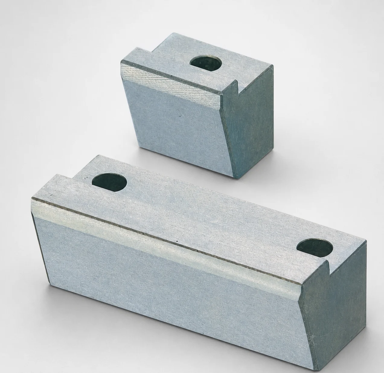
O1 Tool Steel Positioning Locking Blocks with Oil Grooves
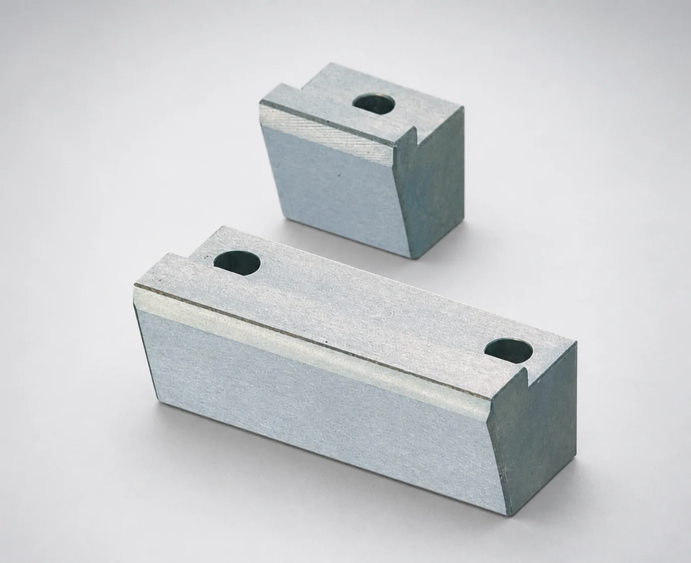
Positioning Locking Blocks Angle Configurable, Oil-Free Options
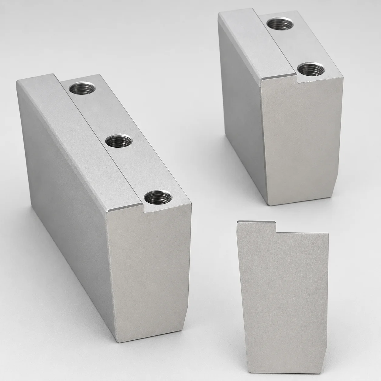
O1 Tool Steel Positioning Locking Blocks - Beveled Edge Bottom (KN)
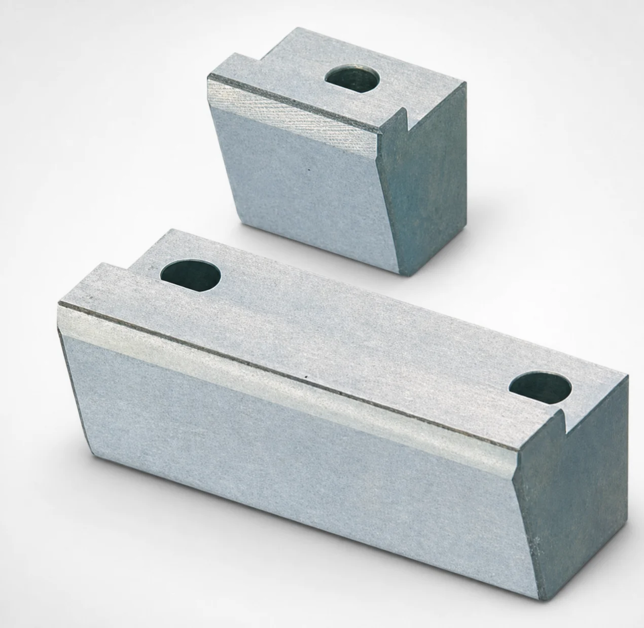
O1 Tool Steel Positioning Locking Blocks - Angle Configurable
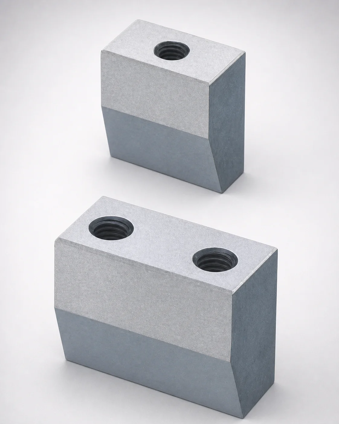
Inlay Type Locking Blocks with Plate Side Setting (Tapped)
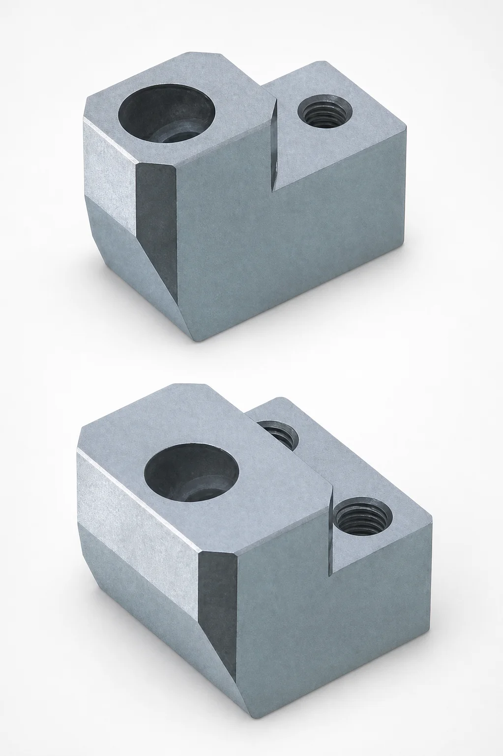
ABPXE Type O1 Tool Steel Positioning Locking Blocks with Angular Pin Hole
Need Custom Specifications?
Our engineering team can help with custom configurations, material selection, and volume pricing.