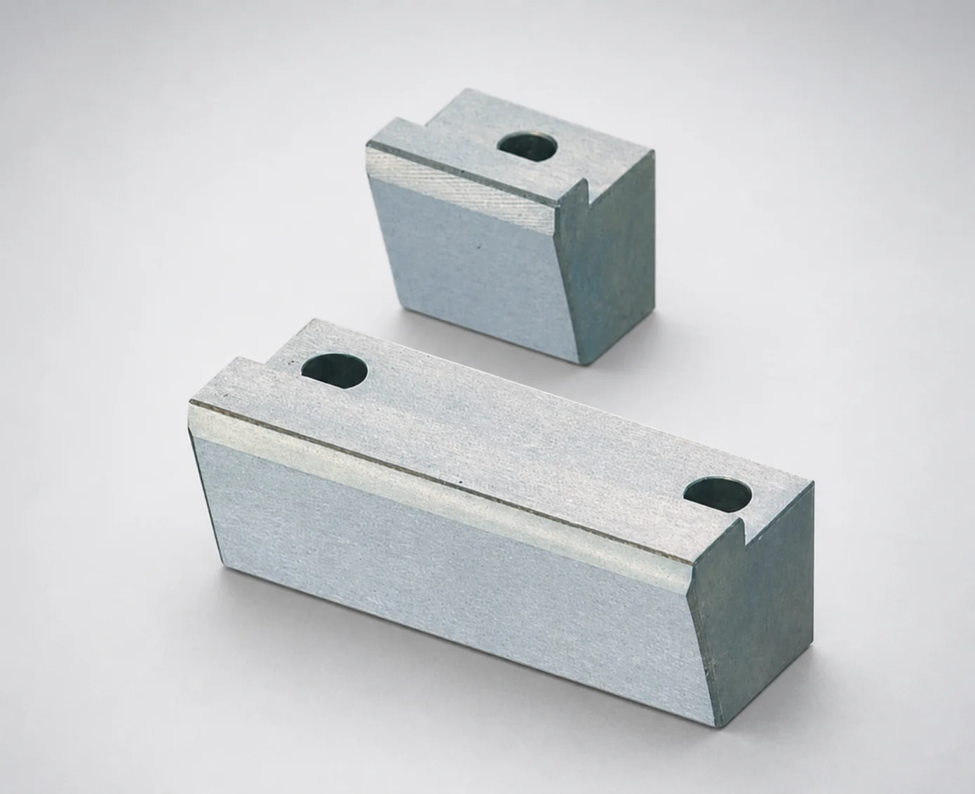
Positioning Locking Blocks Angle Configurable, Oil-Free Options
Positioning Locking Blocks (Angle Configurable) (O1 tool steel or HPM2T) provide stable positioning and locking for mold assembly with oil-free groove options. The PL fixing style supports consistent repeatable alignment during production.
- Angle-configurable locking geometry for reliable mold positioning at setup
- Oil Groove: Non-oil groove option reduces contamination risk in operation
- Tool-steel grade materials such as O1 tool steel or HPM2T for wear-resistant performance
- PL installation compatible with common mold build-up and supporting blocks
Specifications
57 configurations available
| Material | Block Height T (mm) | Block Length L (mm) | A/W (Block width) (mm) | H/E (Inlay Part Dimension) (mm) | G (Angle) (°) | type |
|---|---|---|---|---|---|---|
| HPM2T | 10 | 20 | 13 ~ 48 | 4 | 5 ~ 33 | - |
| HPM2T | 15 | 20 | 13 ~ 58 | 4 | 5 ~ 24 | - |
| HPM2T | 20 | 20 | 13 ~ 58 | 4 | 5 ~ 18 | - |
| HPM2T | 10 | 25 | 18 ~ 98 | 4 | 5 ~ 33 | - |
| HPM2T | 15 | 25 | 18 ~ 108 | 4 | 5 ~ 33 | - |
| HPM2T | 20 | 25 | 23 ~ 108 | 4 | 5 ~ 26 | - |
| HPM2T | 25 | 25 | 23 ~ 108 | 4 | 5 ~ 21 | - |
| HPM2T | 15 | 30 | 33 ~ 128 | 4 | 5 ~ 33 | - |
| HPM2T | 20 | 30 | 33 ~ 128 | 4 | 5 ~ 31 | - |
| HPM2T | 25 | 30 | 33 ~ 128 | 4 | 5 ~ 26 | - |
| HPM2T | 30 | 30 | 33 ~ 128 | 4 | 5 ~ 22 | - |
| HPM2T | 25 | 35 | 38 ~ 128 | 4 | 5 ~ 28 | - |
| HPM2T | 30 | 35 | 38 ~ 128 | 4 | 5 ~ 24 | - |
| HPM2T | 35 | 35 | 48 ~ 128 | 4 | 5 ~ 21 | - |
| HPM2T | 40 | 35 | 48 ~ 128 | 4 | 5 ~ 18 | - |
| HPM2T | 30 | 50 | 78 ~ 148 | 4 | 5 ~ 28 | - |
| HPM2T | 25 | 25 | 23 ~ 98 | 8 | 5 ~ 21 | - |
| HPM2T | 30 | 35 | 38 ~ 128 | 8 | 5 ~ 24 | - |
| HPM2T | 40 | 35 | 48 ~ 128 | 10 | 5 ~ 18 | - |
| HPM2T | 30 | 40 | 48 ~ 138 | 8 | 5 ~ 26 | - |
| HPM2T | 35 | 40 | 48 ~ 138 | 10 | 5 ~ 24 | - |
| HPM2T | 45 | 40 | 48 ~ 138 | 10 | 5 ~ 19 | - |
| HPM2T | 35 | 50 | 58 ~ 148 | 10 | 5 ~ 24 | - |
| HPM2T | 40 | 50 | 58 ~ 148 | 10 | 5 ~ 21 | - |
| HPM2T | 45 | 50 | 58 ~ 148 | 10 | 5 ~ 19 | - |
| O1 Tool Steel | 10 | 20 | 13 ~ 48 | 4 | 5 ~ 33 | - |
| O1 Tool Steel | 15 | 20 | 13 ~ 58 | 4 | 5 ~ 24 | - |
| O1 Tool Steel | 20 | 20 | 13 ~ 58 | 4 | 5 ~ 18 | - |
| O1 Tool Steel | 10 | 25 | 18 ~ 98 | 4 | 5 ~ 33 | - |
| O1 Tool Steel | 15 | 25 | 18 ~ 108 | 4 | 5 ~ 33 | - |
| O1 Tool Steel | 20 | 25 | 23 ~ 108 | 4 | 5 ~ 26 | - |
| O1 Tool Steel | 25 | 25 | 23 ~ 108 | 4 | 5 ~ 21 | - |
| O1 Tool Steel | 15 | 30 | 33 ~ 128 | 4 | 5 ~ 33 | - |
| O1 Tool Steel | 20 | 30 | 33 ~ 128 | 4 | 5 ~ 31 | - |
| O1 Tool Steel | 25 | 30 | 33 ~ 128 | 4 | 5 ~ 26 | - |
| O1 Tool Steel | 30 | 30 | 33 ~ 128 | 4 | 5 ~ 22 | - |
| O1 Tool Steel | 25 | 35 | 38 ~ 128 | 4 | 5 ~ 28 | - |
| O1 Tool Steel | 30 | 35 | 38 ~ 128 | 4 | 5 ~ 24 | - |
| O1 Tool Steel | 35 | 35 | 48 ~ 128 | 4 | 5 ~ 21 | - |
| O1 Tool Steel | 40 | 35 | 48 ~ 128 | 4 | 5 ~ 18 | - |
| O1 Tool Steel | 30 | 40 | 58 ~ 138 | 4 | 5 ~ 26 | - |
| O1 Tool Steel | 35 | 40 | 58 ~ 138 | 4 | 5 ~ 24 | - |
| O1 Tool Steel | 40 | 40 | 68 ~ 138 | 4 | 5 ~ 21 | - |
| O1 Tool Steel | 45 | 40 | 68 ~ 138 | 4 | 5 ~ 19 | - |
| O1 Tool Steel | 30 | 50 | 78 ~ 148 | 4 | 5 ~ 28 | - |
| O1 Tool Steel | 35 | 50 | 78 ~ 148 | 4 | 5 ~ 24 | - |
| O1 Tool Steel | 40 | 50 | 78 ~ 148 | 4 | 5 ~ 21 | - |
| O1 Tool Steel | 45 | 50 | 78 ~ 148 | 4 | 5 ~ 19 | - |
| O1 Tool Steel | 25 | 25 | 23 ~ 98 | 8 | 5 ~ 21 | - |
| O1 Tool Steel | 30 | 35 | 38 ~ 128 | 8 | 5 ~ 24 | - |
Product Guide
Application Scenarios+
These angle-configurable locking blocks are used during injection mold assembly to provide repeatable positioning and a rigid lock between supporting plates and related undercut/plate components. Their PL fixing style is especially suited to mold builds where alignment must remain consistent from commissioning through high-volume production.
- Automotive connector and bracket molds: Use the oil-free groove/non-oil groove variant to minimize lubricant contamination near critical interfaces, helping maintain stable shut alignment during fast cycle runs.
- Electrical enclosure and housing molds: Select the angle-configurable geometry (G = 5°) to fine-tune how components seat during setup, improving repeatability across maintenance cycles.
- General industrial parts molds with plate subassemblies: The configurable block height (T = 10–45 mm) and wide width range (A/W = 13–78 mm) support fit to common plate thickness and cavity/core layout constraints.
With HPM2T or O1 tool steel, the blocks are designed for dependable wear performance where locating surfaces resist fretting during repeated assembly and lock/unlock operations.
Material & Process Details+
This positioning-locking block is offered in HPM2T or O1 tool steel, both tool-steel options selected for stable wear resistance at mold assembly interfaces. The material choice balances surface durability with toughness needs depending on load and assembly frequency.
- O1 tool steel: Commonly used where good toughness and machinability are required for precision components; it typically performs well for wear resistance when properly heat treated.
- HPM2T: A high-performance tool steel grade intended to improve wear behavior at locking faces, supporting longer service life in repeat-use molds.
While the supplied data lists the grade options, it does not specify hardness or a specific heat-treatment state (e.g., quench & temper, nitriding). For best results, engineers should confirm the delivered hardness (HRC target) and the shop’s heat-treatment process to ensure the desired wear–toughness trade-off for the intended mold duty.
Sizing & Selection Guide+
To select the correct locking block, start by matching the block height and inlay geometry to your mold plate/interface layout. The available ranges are T = 10–45 mm (block height) and H/E = 4, 8, or 10 mm (inlay part dimension). Choose the block width from A/W = 13–78 mm to fit the plate supporting area without interference.
- Match length (L): Select from the offered values L = 20, 25, 30, 35, 40, or 50 mm based on the available space along the locating edge in your cavity/core stack.
- Match the angle function: The angle parameter is G = 5°, so compatibility depends on your mating locating surface geometry being designed for that seating angle.
- Fit and tolerance: Use your mold assembly drawing to verify allowable clearance/gap at the locking interface and ensure the selected dimensions avoid clamp-area contact during PL installation.
When possible, confirm whether your design expects a specific inlay depth (H/E) and that the plate thickness supports the selected T without weakening surrounding features.
Frequently Asked Questions
How does the angle-configurable geometry affect positioning during PL mold installation?+
What size parameters must be matched when designing the cavity/core stack for these locking blocks?+
When should I choose HPM2T versus O1 tool steel for the locking face?+
What is the advantage of the oil-free / non-oil groove option in undercuts-plates applications?+
Is block height T and inlay dimension H/E interchangeable, or do they need exact selection?+
Related Products
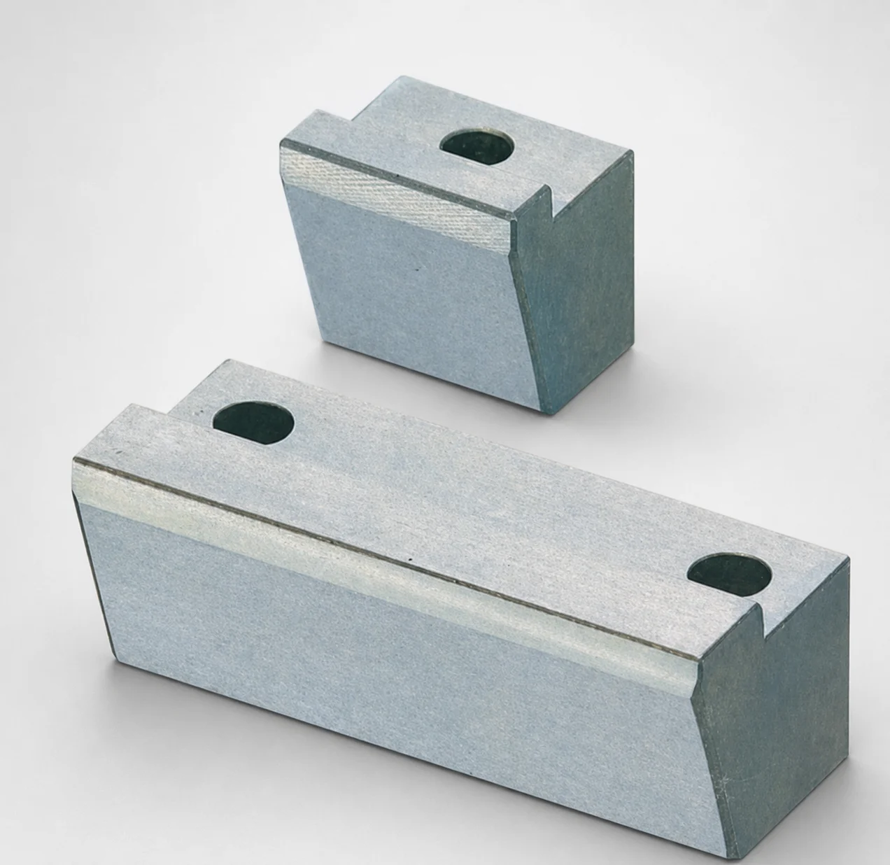
O1 Tool Steel Positioning Locking Blocks with Oil Grooves
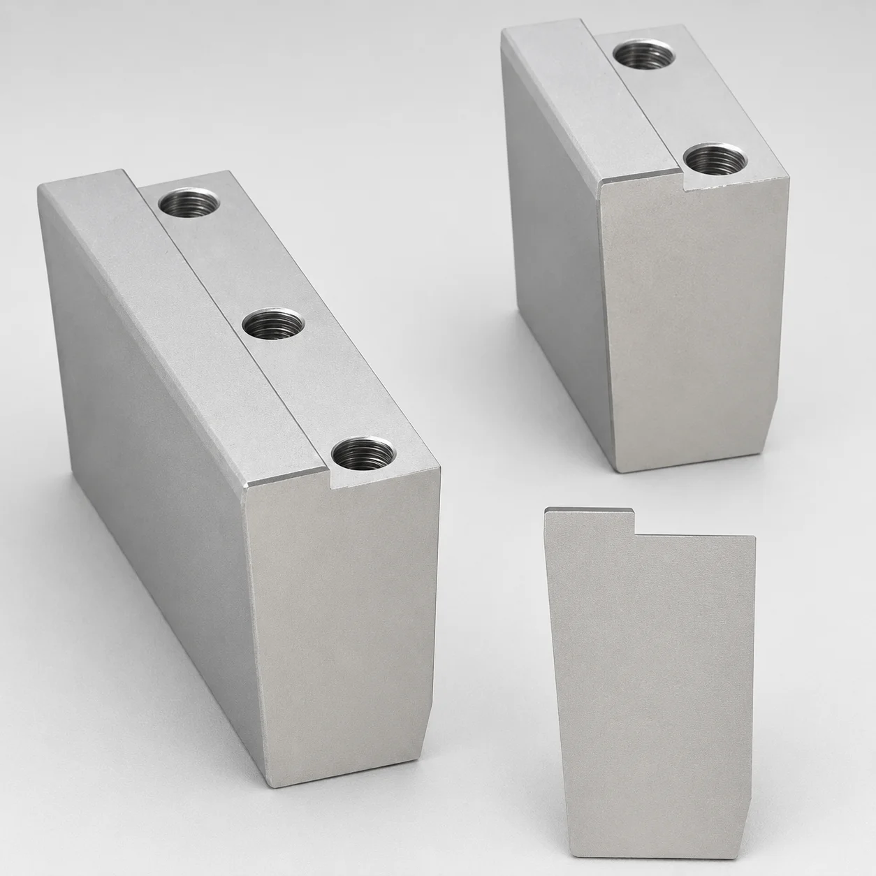
O1 Tool Steel Positioning Locking Blocks - Beveled Edge Bottom (KN)
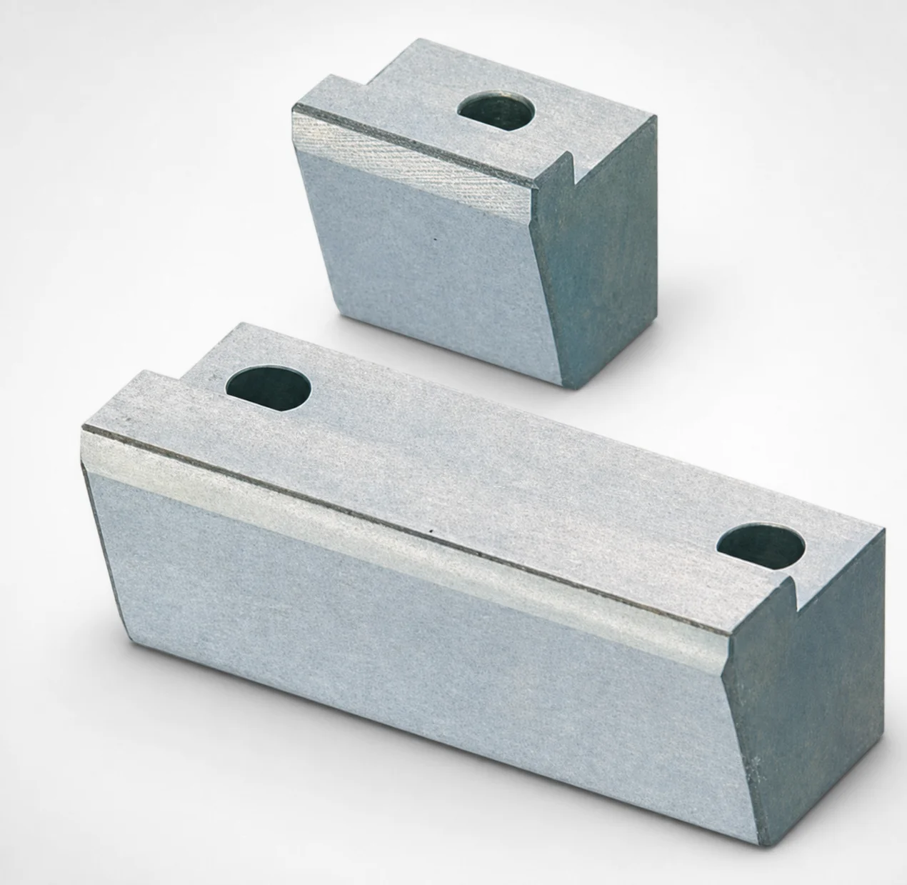
O1 Tool Steel Positioning Locking Blocks - Angle Configurable
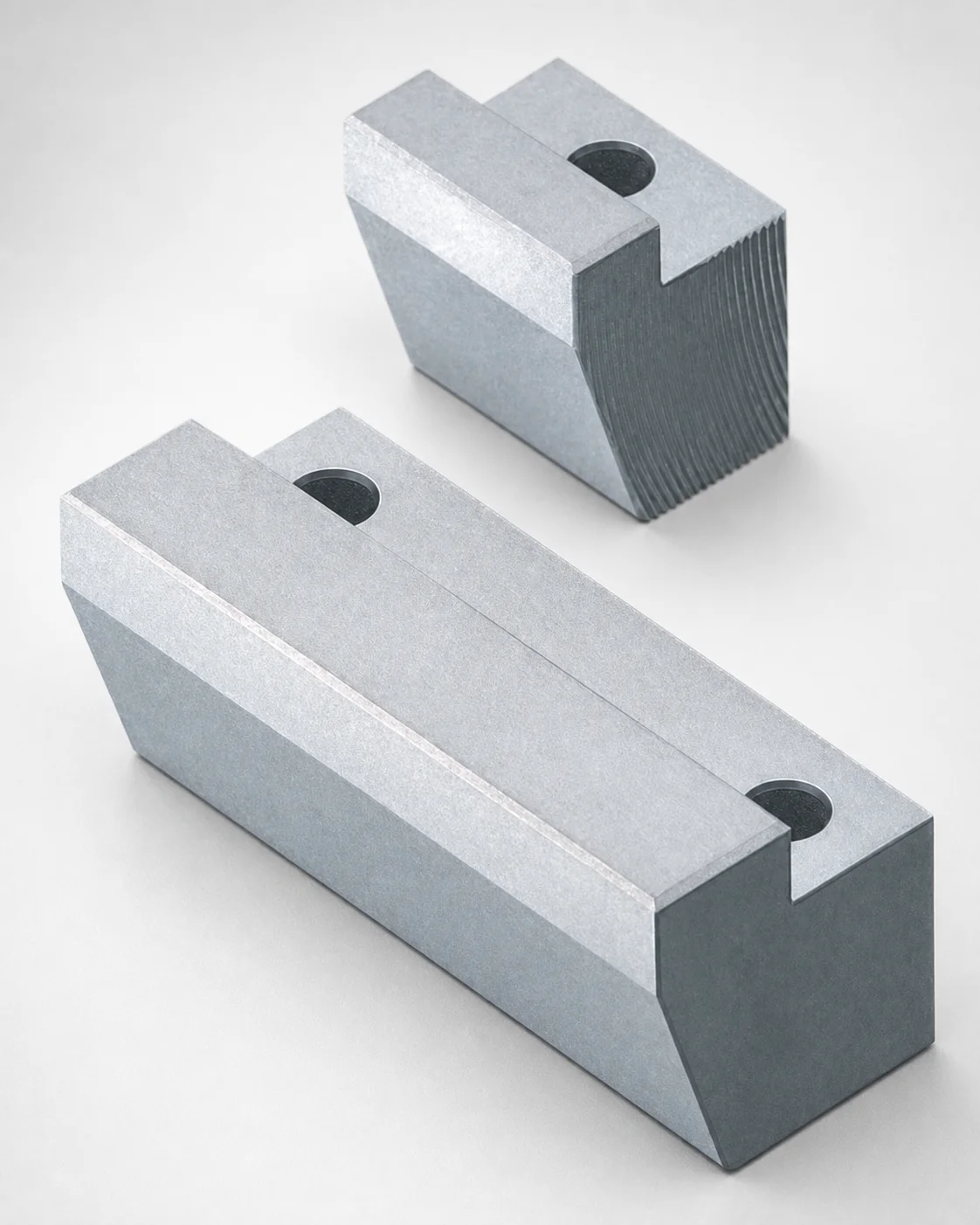
Locking Blocks - Fixed Angle & Inlay Height Configurable
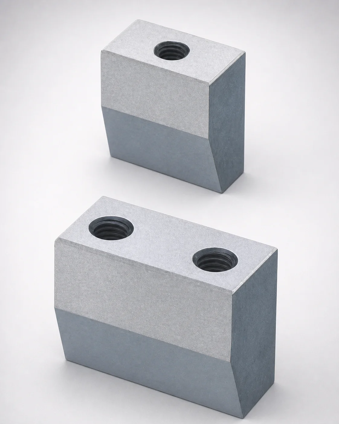
Inlay Type Locking Blocks with Plate Side Setting (Tapped)
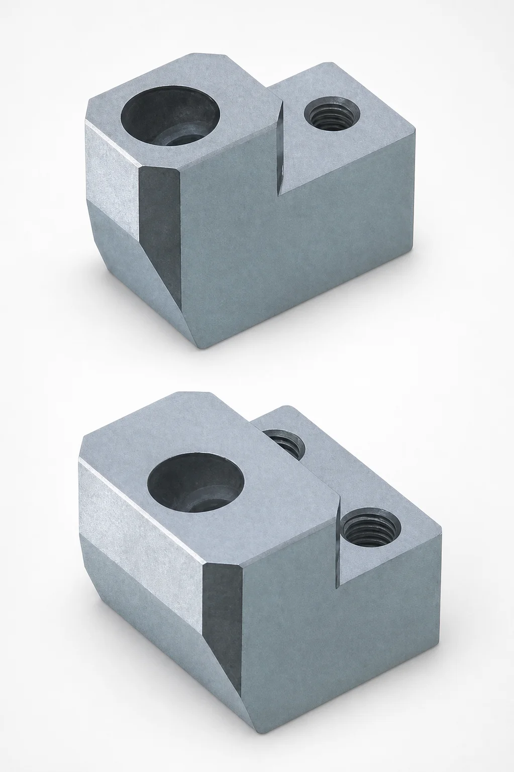
ABPXE Type O1 Tool Steel Positioning Locking Blocks with Angular Pin Hole
Need Custom Specifications?
Our engineering team can help with custom configurations, material selection, and volume pricing.