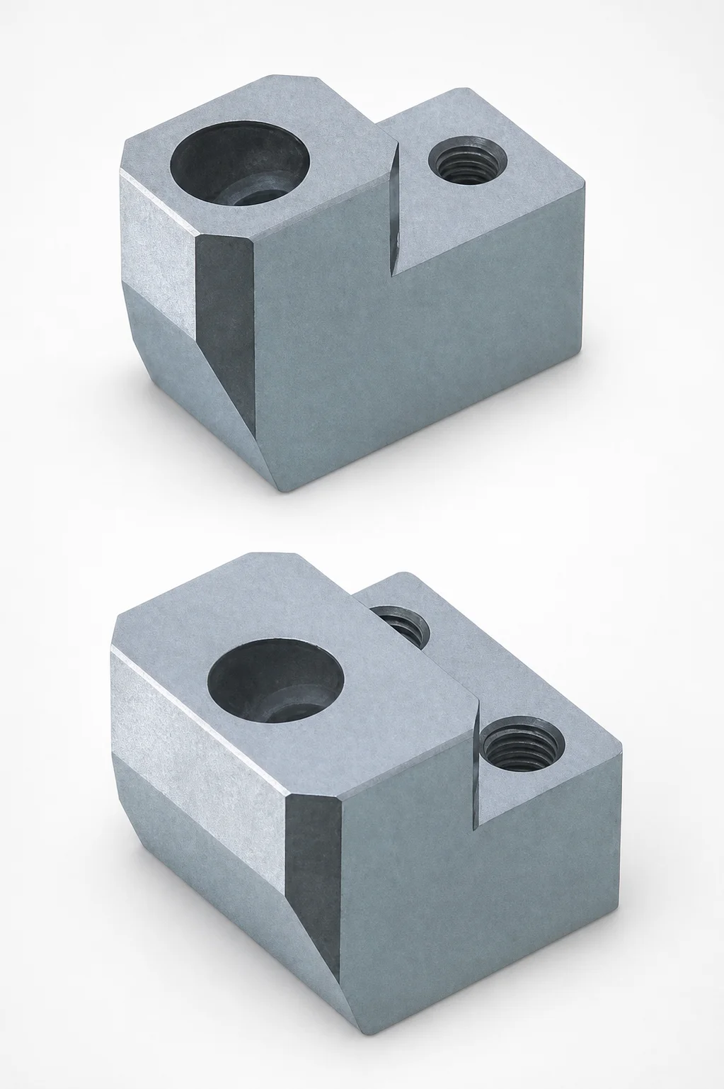
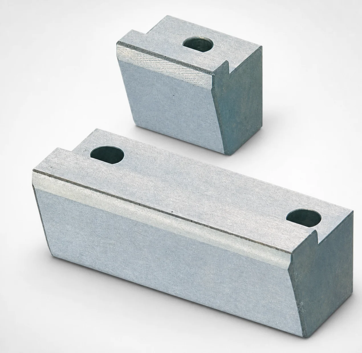
ABPXE Type O1 Tool Steel Positioning Locking Blocks with Angular Pin Hole
Positioning locking blocks with angular pin hole (O1 tool steel) provide reliable geometric location for mold and die assemblies using the fixed ABPXE type structure. The included angular hole supports accurate alignment with mating pins while maintaining repeatable positioning.
- Angular pin hole design ensures stable part positioning
- Built from O1 tool steel for durable wear resistance
- Compatible with PL installation bolt fixing for secure mounting
- Fixed ABPXE type configuration for standard locking applications
Specifications
3 configurations available
| A/W (Block width) (mm) | A (Angle) (°) | type |
|---|---|---|
| 15 | 15 ~ 20 | - |
| 20 | 15 ~ 20 | - |
| 25 | 15 ~ 20 | - |
Product Guide
Application Scenarios+
These ABPXE positioning locking blocks with an angular pin hole are used in injection mold and die assemblies where repeatable part location is critical, especially during plate separation and reassembly. The angular pin hole variant helps alignment by engaging with mating pins at a controlled angle, reducing the risk of rotational misregistration.
- Automotive and appliance connector molds: Use the locking block on undercut plate systems to stabilize core/cavity plate alignment through high-cycle spotting and teardown cycles. O1 tool steel durability supports wear over repeated positioning.
- Electronics enclosure tooling: Install on steel support plates with PL bolt fixing to hold reference geometry firmly, improving consistency for thin-wall or tolerance-sensitive features.
- General undercuts-plates applications: Select the fixed ABPXE type configuration for standard locking layouts where the angular engagement helps maintain repeatability between maintenance intervals.
With available block widths (15, 20, 25 mm) and a fixed angle range of 15–20°, this variant is suited to precise locating without requiring custom geometry.
Material & Process Details+
This product is made from O1 tool steel. O1 is an oil-hardening tool steel known for good toughness and wear resistance in tooling applications where dimensional stability and reliable locating surfaces matter.
- Heat treatment (typical for O1): Quenched and tempered after machining to achieve a balance of hardness and toughness for long service life.
- Hardness & wear vs. toughness trade-off: Higher tempering targets improved toughness but can reduce wear resistance; lower tempering increases hardness and abrasion resistance but may reduce impact toughness. The final hardness is normally selected based on cycle rate and contact stress.
- Manufacturing process: Machined block geometry with the angular pin hole for precise engagement, followed by heat treatment to lock in wear performance on the locating interfaces.
If your process involves extremely abrasive conditions, alternative wear-focused tool steels may offer improved resistance, but O1’s balance is often well-suited for repeatable positioning components like this locking block.
Sizing & Selection Guide+
To select the correct locking block, match the block width A/W and the angle A to your mating reference design. This series provides A/W = 15, 20, or 25 mm, and the fixed angle A = 15–20°.
- Choose A/W (block width): Select 15 mm for compact plate layouts, 20 mm for common undercuts-plate spacing, and 25 mm when more material width is needed for clamp/bolt spacing and positional rigidity.
- Verify angle compatibility: Ensure the mating pin’s alignment geometry corresponds to the fixed angular configuration (15–20°) so the angular hole seats correctly.
- Tolerance/fit considerations: Positioning features typically require consistent hole-to-pin fit to avoid repeatability loss. Confirm your pin diameter tolerance and surface finish are compatible with the angular hole for stable seating.
- Fixed vs configurable: The configuration is fixed ABPXE type; the selection is limited to the available A/W sizes and the specified angular range.
Once A/W and angle are matched, confirm the PL bolt fixing pattern in your plate stack-up to maintain proper clamping without inducing side load on the locating surfaces.
Frequently Asked Questions
Which block width (A/W) should I choose for my undercuts-plates stack-up?+
The available A/W (block width) for this series is 15, 20, or 25 mm. Choose the size that matches your plate spacing and provides sufficient material around the mounting area for PL bolt fixing without creating excessive clamp distortion. If you have limited space, use A/W = 15 mm; for higher rigidity, consider 20 or 25 mm.
Is the angular pin hole angle configurable, or fixed for ABPXE Type O1 locking blocks?+
This locking block uses a fixed ABPXE Type configuration with the angle A = 15–20°. In practice, you should verify your mating pin’s angular geometry falls within the same specified range so the angular hole can seat consistently. If your tooling design targets a single angle, confirm which value in the 15–20° range is required by your mating parts.
Why use O1 tool steel for a positioning locking block with an angular hole?+
Because the component must maintain repeatable geometry under clamping and repeated engagement, O1 tool steel is selected for a useful balance of wear resistance and toughness. The part is typically quenched and tempered to reach service hardness, improving durability at the locating surfaces. This makes it suitable for positioning elements that see frequent assembly/disassembly cycles.
How does PL bolt fixing impact mounting and alignment stability?+
This series includes compatibility with PL installation bolt fixing for secure mounting. Proper bolt fixing helps prevent micro-movement between plate maintenance cycles, which is important for maintaining the correct seating of the angular pin hole. When designing the plate stack, ensure clamping does not introduce side load that could shift the locating interfaces.
What tolerances should I confirm between the angular pin hole and the mating pin?+
Even though specific tolerance values are not listed here, positioning features generally require a controlled pin-to-hole fit to preserve repeatability. Confirm your mating pin diameter tolerance and surface finish so the pin seats reliably in the angular pin hole without excessive clearance or binding. Also ensure the angle match (15–20°) is correct so the contact is consistent across assemblies.
Related Products
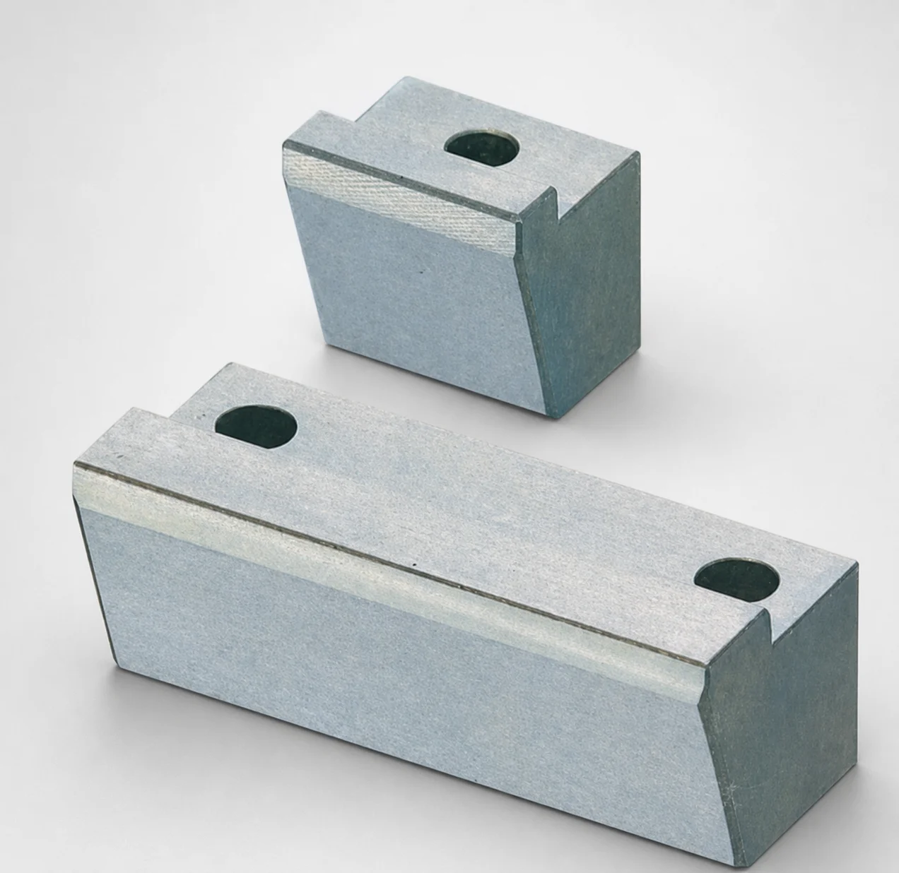
O1 Tool Steel Positioning Locking Blocks with Oil Grooves
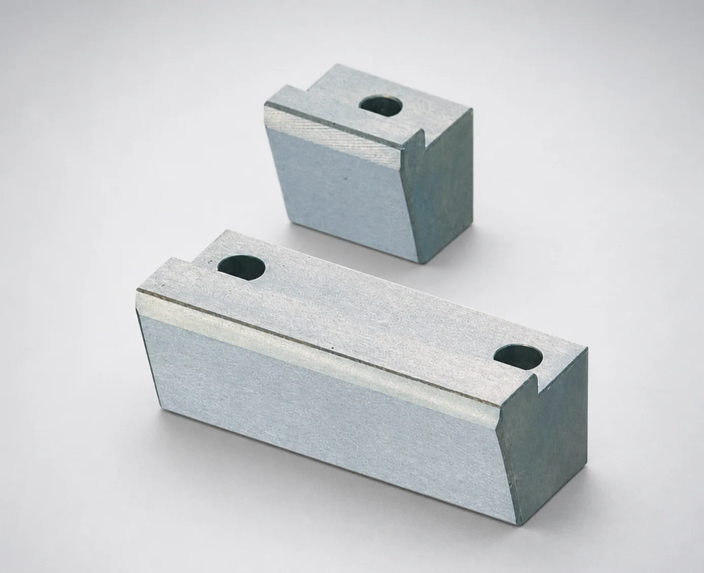
Positioning Locking Blocks Angle Configurable, Oil-Free Options
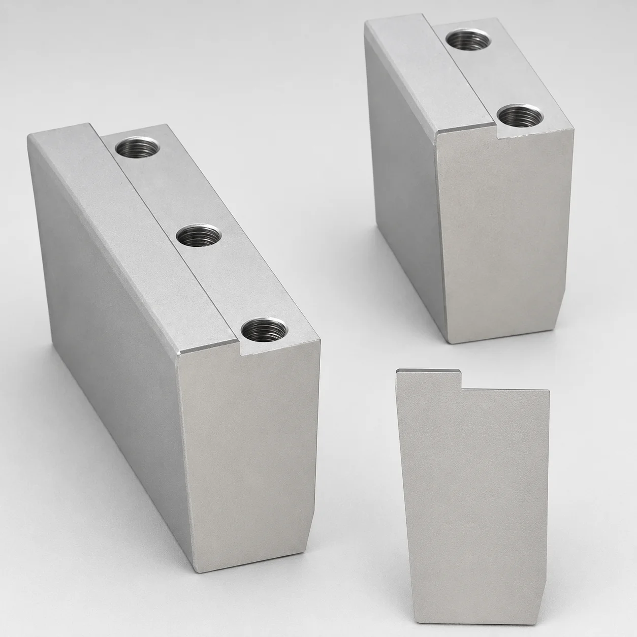
O1 Tool Steel Positioning Locking Blocks - Beveled Edge Bottom (KN)
O1 Tool Steel Positioning Locking Blocks - Angle Configurable
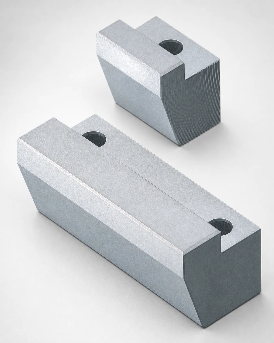
Locking Blocks - Fixed Angle & Inlay Height Configurable
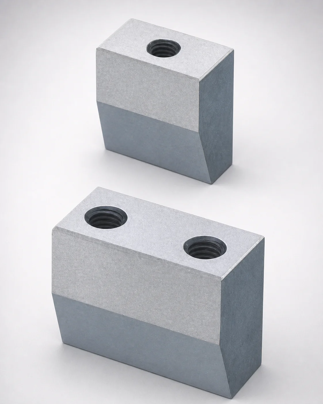
Inlay Type Locking Blocks with Plate Side Setting (Tapped)
Need Custom Specifications?
Our engineering team can help with custom configurations, material selection, and volume pricing.