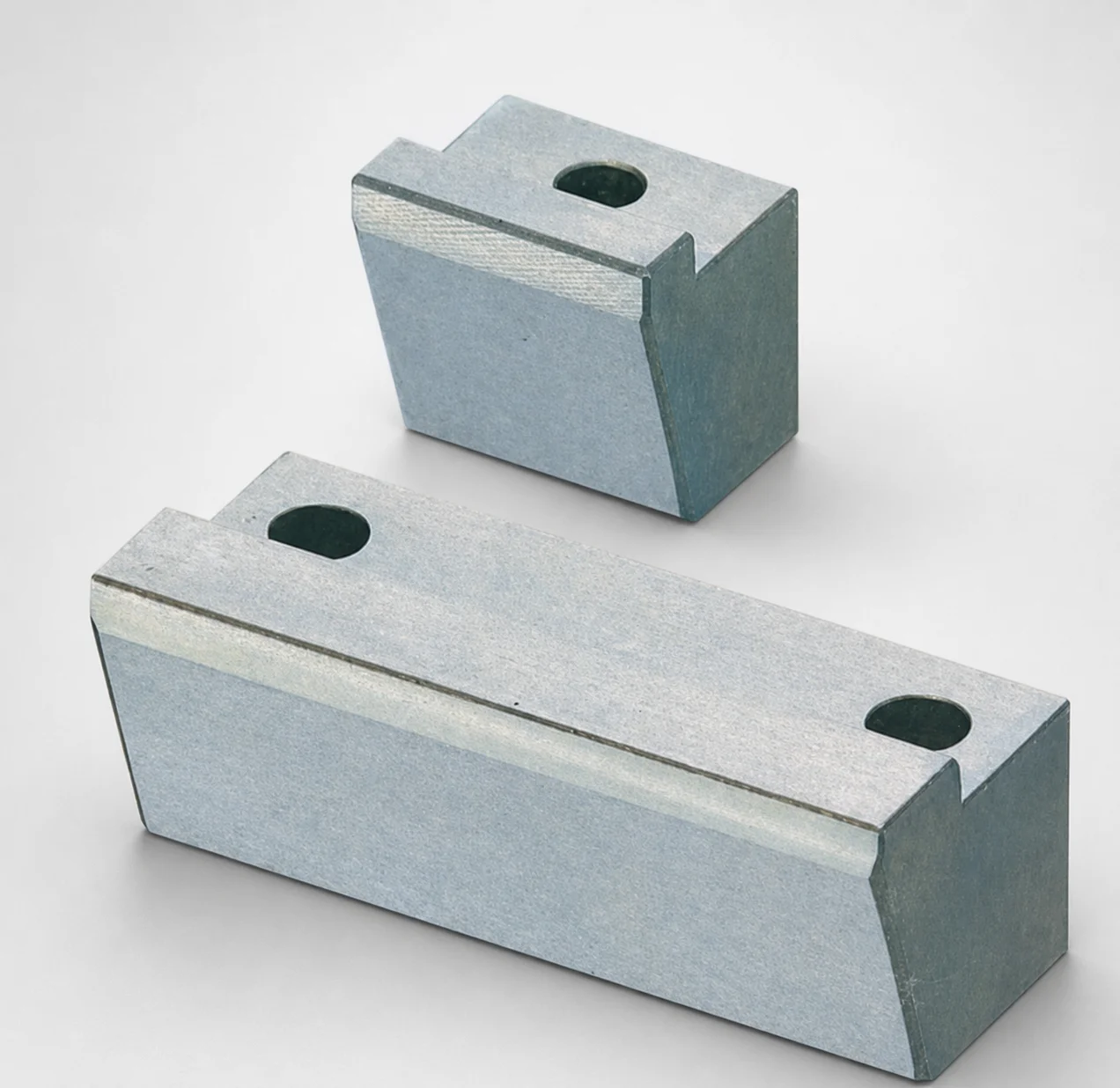
O1 Tool Steel Positioning Locking Blocks with Oil Grooves
Positioning locking blocks with oil grooves (O1 tool steel) provide repeatable location control for precision mold and die assemblies using PL installation. The 4 mm inlay height supports consistent locking engagement and stable part alignment.
- Oil groove design helps manage lubricant and reduces friction during positioning
- O1 tool steel construction with robust wear resistance for long service life
- Compatible with inlay height 4 mm for reliable locking geometry in assembly
- Positioning type blocks suited to tooling applications requiring repeatable location
Specifications
30 configurations available
| Oil Groove | Block Height T (mm) | Block Length L (mm) | A/W (Block width) (mm) | G (Angle) (°) | type |
|---|---|---|---|---|---|
| Non-oil groove | 10 | 20 | 13 ~ 48 | 17 ~ 22 | - |
| Non-oil groove | 15 | 20 | 15 ~ 58 | 15 ~ 22 | - |
| Non-oil groove | 20 | 20 | 15 ~ 58 | 15 ~ 17 | - |
| Non-oil groove | 10 | 25 | 23 ~ 58 | 17 ~ 22 | - |
| Non-oil groove | 15 | 25 | 18 ~ 78 | 15 ~ 22 | - |
| Non-oil groove | 20 | 25 | 18 ~ 78 | 15 ~ 22 | - |
| Non-oil groove | 25 | 30 | 33 ~ 78 | 15 ~ 22 | - |
| Non-oil groove | 30 | 30 | 33 ~ 78 | 15 ~ 22 | - |
| Non-oil groove | 10 | 20 | 13 ~ 48 | 17 ~ 22 | - |
| Non-oil groove | 15 | 20 | 15 ~ 58 | 15 ~ 22 | - |
| Non-oil groove | 20 | 20 | 15 ~ 58 | 15 ~ 17 | - |
| Non-oil groove | 10 | 25 | 23 ~ 58 | 17 ~ 22 | - |
| Non-oil groove | 15 | 25 | 18 ~ 78 | 15 ~ 22 | - |
| Non-oil groove | 20 | 25 | 18 ~ 78 | 15 ~ 22 | - |
| Non-oil groove | 25 | 30 | 33 ~ 78 | 15 ~ 22 | - |
| Non-oil groove | 30 | 30 | 33 ~ 78 | 15 ~ 22 | - |
| Oil groove | 15 | 20 | 15 ~ 48 | 15 ~ 22 | - |
| Oil groove | 20 | 20 | 15 ~ 48 | 15 ~ 17 | - |
| Oil groove | 15 | 25 | 28 ~ 78 | 15 ~ 22 | - |
| Oil groove | 20 | 25 | 28 ~ 78 | 15 ~ 22 | - |
| Oil groove | 20 | 30 | 33 ~ 78 | 15 ~ 22 | - |
| Oil groove | 25 | 30 | 33 ~ 78 | 15 ~ 22 | - |
| Oil groove | 30 | 30 | 33 ~ 78 | 15 ~ 22 | - |
| Oil-free | 15 | 20 | 15 ~ 48 | 15 ~ 22 | - |
| Oil-free | 20 | 20 | 15 ~ 48 | 15 ~ 17 | - |
| Oil-free | 15 | 25 | 28 ~ 78 | 15 ~ 22 | - |
| Oil-free | 20 | 25 | 28 ~ 78 | 15 ~ 22 | - |
| Oil-free | 20 | 30 | 33 ~ 78 | 15 ~ 22 | - |
| Oil-free | 25 | 30 | 33 ~ 78 | 15 ~ 22 | - |
| Oil-free | 30 | 30 | 33 ~ 78 | 15 ~ 22 | - |
Product Guide
Application Scenarios+
Positioning locking blocks are used inside injection mold base assemblies and die structures to deliver repeatable location control during core/cavity or plate installation. In PL-based setups, the oil-groove variant supports smoother engagement by managing lubrication at the contact area, which helps maintain consistent positioning over repeated service cycles.
- Automotive connector and bracket molds: Use for alignment of undercut-related plates where precise plate-to-plate repeatability reduces mismatch at shut-off and maintains dimensional stability.
- Electronics enclosure and insert tooling: Suitable where repeated teardown/reassembly is common; the locking geometry with a 4 mm inlay height helps maintain stable part alignment.
- Precision transfer and multi-station die assemblies: The variant is suited for tooling that benefits from lower friction during positioning, improving repeatability and wear behavior on contact surfaces.
Because this variant is designed around PL installation with an oil-groove contact feature, it is especially relevant when controlled lubrication and consistent locking engagement are required.
Material & Process Details+
This product is made from O1 tool steel, commonly selected for tooling components that need good wear resistance and dimensional stability in service. In this application, the oil-groove design supports reduced friction at the locating interface, which helps preserve surface condition during repeated assembly cycles.
- Steel grade context: O1 tool steel is an air-hardening tool steel (historically associated with AISI O1/“D2-like” wear-focused behavior), used in parts requiring a balance of hardness and toughness.
- Heat treatment (typical for O1): Usually quenched and tempered from austenitizing temperature to achieve target hardness; final properties depend on the chosen temper.
- Hardness & trade-offs: Higher hardness improves wear resistance but can reduce toughness; selecting temper severity is critical to avoid chipping under locating load and vibration.
If you require different lubrication behavior, the oil groove option can be chosen from non-oil groove / oil-free through oil groove versions to match your assembly lubrication strategy.
Sizing & Selection Guide+
Select the locking block dimensions to match the plate and locating interface geometry in your mold assembly. Start with the block height T (10, 15, 20, 25, 30 mm) to ensure the block reaches the intended inlay engagement depth for stable locking; the meta notes an inlay height of 4 mm, so verify your PL installation design provides that inlay feature.
- Block width (A/W): Choose within 13 ~ 33 mm so the block supports the required contact area without interfering with adjacent components.
- Block length L: Select 20, 25, or 30 mm to fit the available plate slot/undercut region while maintaining proper clearance for assembly and thermal growth.
- Angle (G): Match the locating ramp/profile using the available ranges 17–22°, 15–22°, or 15–17° to align with your undercut plate geometry.
Because this is a positioning feature, confirm your drawing-based clearance and fit between the block and the mating PL surfaces; tighter fits improve repeatability, but require attention to lubrication and burr control.
Frequently Asked Questions
How does the oil groove option affect positioning repeatability in PL installation?+
What inlay height is supported by this locking block design, and how should it influence plate selection?+
How do I choose block height (T) and width (A/W) to avoid interference while maintaining locking contact?+
Which angle (G) range should be used for undercut plate geometry matching?+
Is this component suitable for wear-heavy locating surfaces compared with oil-free variants?+
Related Products
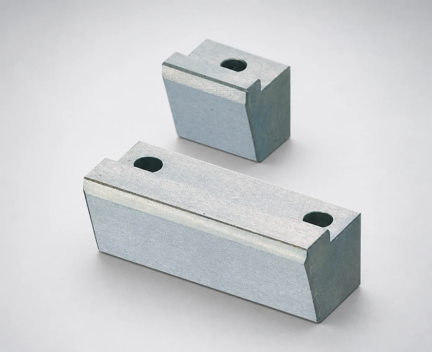
Positioning Locking Blocks Angle Configurable, Oil-Free Options
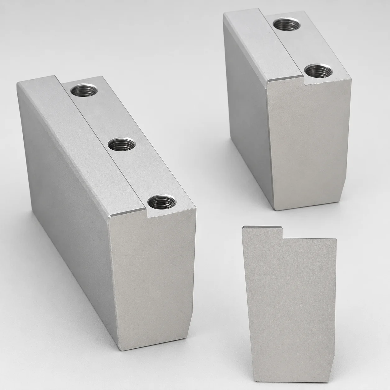
O1 Tool Steel Positioning Locking Blocks - Beveled Edge Bottom (KN)
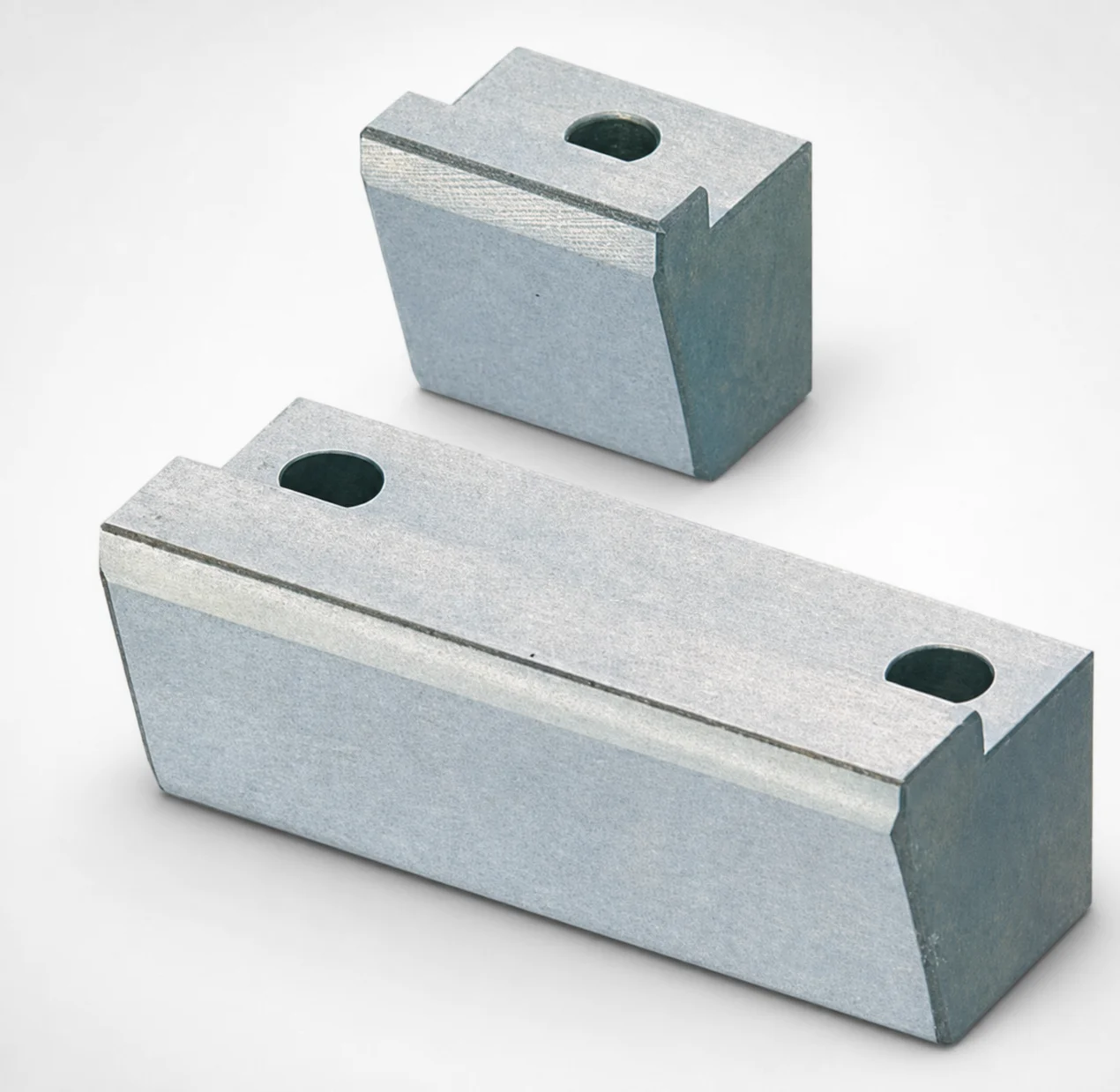
O1 Tool Steel Positioning Locking Blocks - Angle Configurable
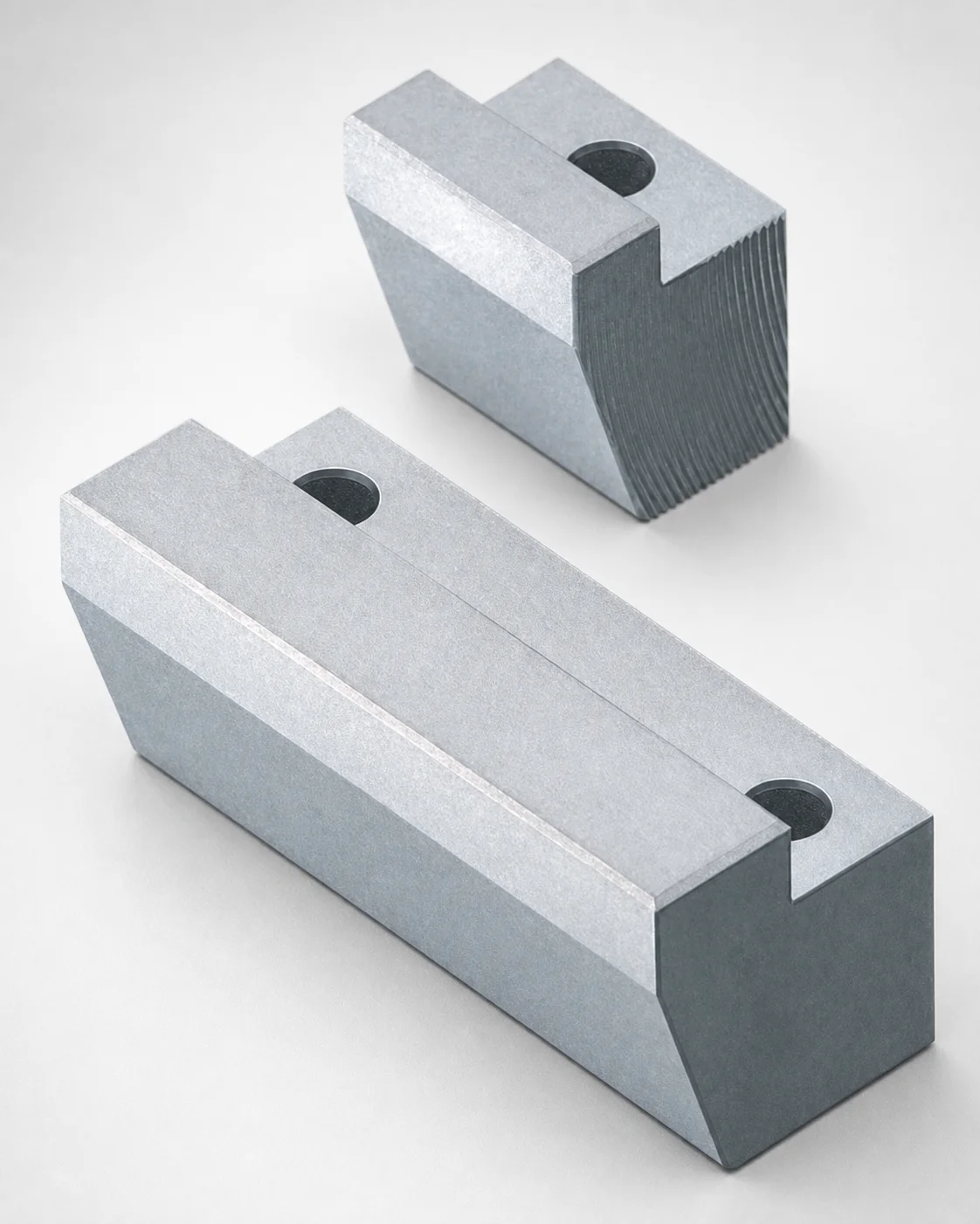
Locking Blocks - Fixed Angle & Inlay Height Configurable
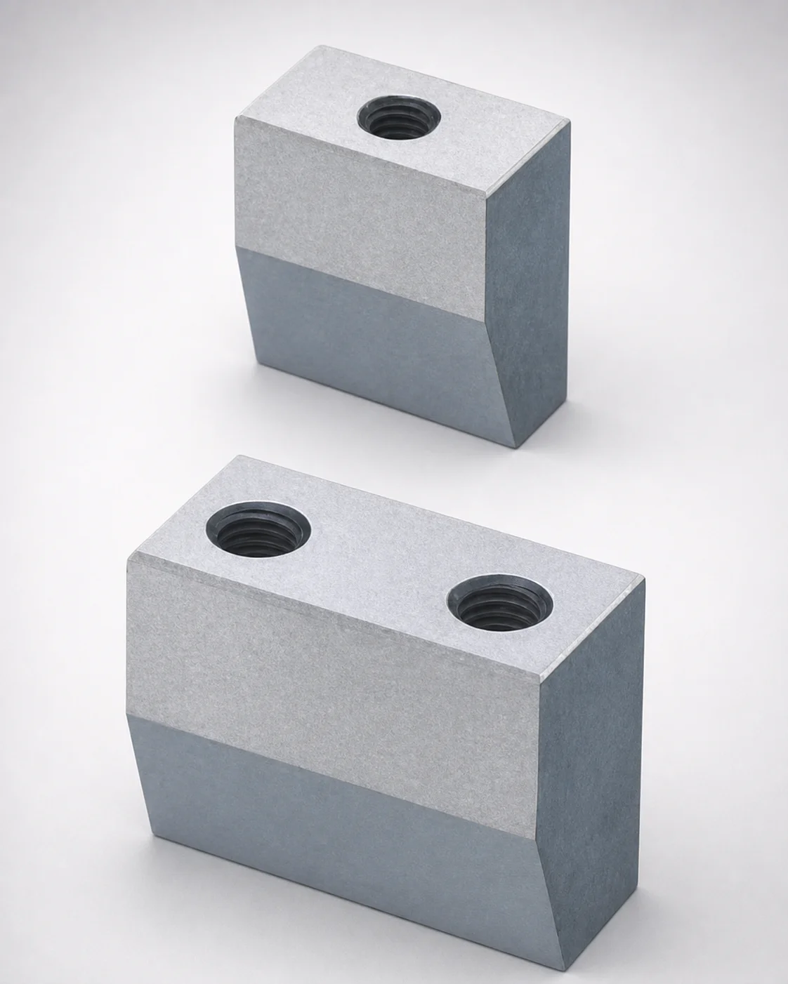
Inlay Type Locking Blocks with Plate Side Setting (Tapped)
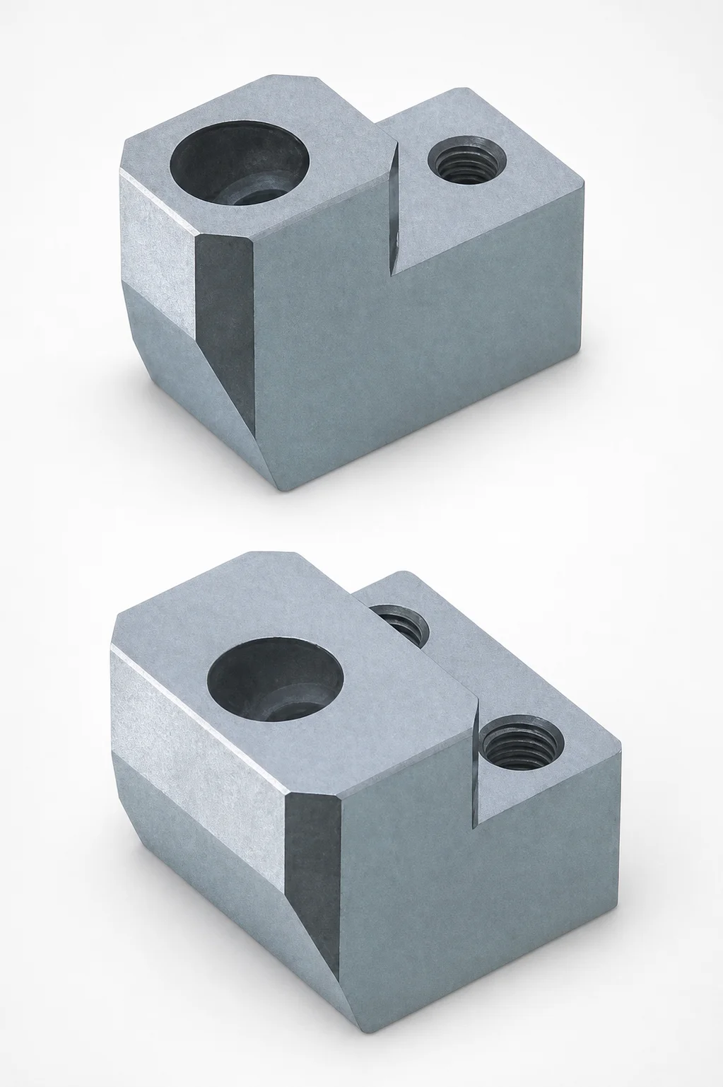
ABPXE Type O1 Tool Steel Positioning Locking Blocks with Angular Pin Hole
Need Custom Specifications?
Our engineering team can help with custom configurations, material selection, and volume pricing.