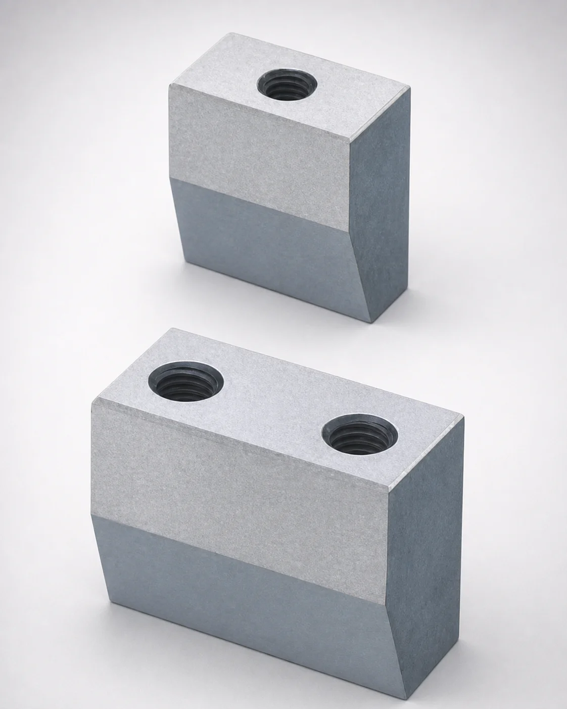
Inlay Type Locking Blocks with Plate Side Setting (Tapped)
Inlay type locking blocks with plate side setting (tapped) are designed for repeatable positioning in mold and die assemblies. Configurable inlay height and width help you match the locking geometry while maintaining stable bolt fixing from the plate side.
- Plate side setting with tap provides positive bolt fixing and simplified assembly
- Non-oil groove option supports cleaner sliding behavior and easier maintenance
- Supports configurable inlay height and inlay part dimensions for locking accuracy
- Used in molding tooling to secure angular locking arrangements with controlled inlay interface
Specifications
40 configurations available
| Material | Block Height T (mm) | Block Length L (mm) | A/W (Block width) (mm) | H/E (Inlay Part Dimension) (mm) | G (Angle) (°) | type |
|---|---|---|---|---|---|---|
| HPM2T | 20 | 15 | 15 ~ 48 | 10 ~ 13 | 5 ~ 33 | - |
| HPM2T | 20 | 15 | 15 ~ 48 | 2 ~ 9 | 5 ~ 33 | - |
| HPM2T | 25 | 15 | 15 ~ 48 | 10 ~ 15 | 5 ~ 33 | - |
| HPM2T | 25 | 15 | 15 ~ 48 | 2 ~ 9 | 5 ~ 33 | - |
| HPM2T | 30 | 15 | 15 ~ 48 | 10 ~ 20 | 5 ~ 33 | - |
| HPM2T | 30 | 15 | 15 ~ 48 | 2 ~ 9 | 5 ~ 33 | - |
| HPM2T | 35 | 15 | 28 ~ 58 | 10 ~ 25 | 5 ~ 28 | - |
| HPM2T | 40 | 15 | 28 ~ 58 | 10 ~ 30 | 5 ~ 22 | - |
| HPM2T | 30 | 20 | 33 ~ 58 | 10 ~ 20 | 5 ~ 33 | - |
| HPM2T | 30 | 20 | 33 ~ 58 | 2 ~ 9 | 5 ~ 33 | - |
| HPM2T | 35 | 20 | 33 ~ 58 | 10 ~ 25 | 5 ~ 33 | - |
| HPM2T | 35 | 20 | 33 ~ 58 | 2 ~ 9 | 5 ~ 33 | - |
| HPM2T | 40 | 20 | 33 ~ 78 | 10 ~ 30 | 5 ~ 30 | - |
| HPM2T | 50 | 20 | 33 ~ 78 | 12 ~ 40 | 5 ~ 24 | - |
| HPM2T | 35 | 25 | 38 ~ 78 | 12 ~ 25 | 5 ~ 33 | - |
| HPM2T | 40 | 25 | 38 ~ 78 | 12 ~ 30 | 5 ~ 33 | - |
| HPM2T | 50 | 25 | 48 ~ 78 | 12 ~ 40 | 5 ~ 30 | - |
| HPM2T | 40 | 30 | 78 ~ 98 | 12 ~ 30 | 5 ~ 33 | - |
| HPM2T | 50 | 30 | 78 ~ 98 | 12 ~ 40 | 5 ~ 33 | - |
| HPM2T | 60 | 30 | 78 ~ 98 | 12 ~ 50 | 5 ~ 30 | - |
| O1 Tool Steel | 20 | 15 | 15 ~ 48 | 10 ~ 13 | 5 ~ 33 | - |
| O1 Tool Steel | 20 | 15 | 15 ~ 48 | 2 ~ 9 | 5 ~ 33 | - |
| O1 Tool Steel | 25 | 15 | 15 ~ 48 | 10 ~ 15 | 5 ~ 33 | - |
| O1 Tool Steel | 25 | 15 | 15 ~ 48 | 2 ~ 9 | 5 ~ 33 | - |
| O1 Tool Steel | 30 | 15 | 15 ~ 48 | 10 ~ 20 | 5 ~ 33 | - |
| O1 Tool Steel | 30 | 15 | 15 ~ 48 | 2 ~ 9 | 5 ~ 33 | - |
| O1 Tool Steel | 35 | 15 | 28 ~ 58 | 10 ~ 25 | 5 ~ 28 | - |
| O1 Tool Steel | 40 | 15 | 28 ~ 58 | 10 ~ 30 | 5 ~ 22 | - |
| O1 Tool Steel | 30 | 20 | 30 ~ 58 | 10 ~ 20 | 5 ~ 33 | - |
| O1 Tool Steel | 30 | 20 | 30 ~ 58 | 2 ~ 9 | 5 ~ 33 | - |
| O1 Tool Steel | 35 | 20 | 33 ~ 58 | 10 ~ 25 | 5 ~ 33 | - |
| O1 Tool Steel | 35 | 20 | 33 ~ 58 | 2 ~ 9 | 5 ~ 33 | - |
| O1 Tool Steel | 40 | 20 | 33 ~ 78 | 10 ~ 30 | 5 ~ 30 | - |
| O1 Tool Steel | 50 | 20 | 33 ~ 78 | 12 ~ 40 | 5 ~ 24 | - |
| O1 Tool Steel | 35 | 25 | 38 ~ 78 | 12 ~ 25 | 5 ~ 33 | - |
| O1 Tool Steel | 40 | 25 | 38 ~ 78 | 12 ~ 30 | 5 ~ 33 | - |
| O1 Tool Steel | 50 | 25 | 48 ~ 78 | 12 ~ 40 | 5 ~ 30 | - |
| O1 Tool Steel | 40 | 30 | 78 ~ 98 | 12 ~ 30 | 5 ~ 33 | - |
| O1 Tool Steel | 50 | 30 | 78 ~ 98 | 12 ~ 40 | 5 ~ 33 | - |
| O1 Tool Steel | 60 | 30 | 78 ~ 98 | 12 ~ 50 | 5 ~ 30 | - |
Product Guide
Application Scenarios+
These inlay type locking blocks are used in injection mold and die assemblies where repeatable positioning of an undercut or angular locking feature is critical. The plate side setting with a tapped interface enables positive bolt fixing from the plate side, helping reduce assembly variability during tooling build-up and maintenance.
Common scenarios include automotive and appliance connector housing molds, where controlled inlay geometry keeps locking alignment for sliding cores or side-action components. They also fit electronics enclosure and camera-module housings, supporting consistent undercut engagement while maintaining a stable bolted connection under normal production cycles.
For medical device housings and other high-cleanliness applications, the available non-oil groove option helps promote cleaner sliding behavior and simpler upkeep. The adjustable inlay part dimension range (H/E 2–12 mm) and configurable block dimensions make this variant well suited for matching locking geometry without redesigning the entire plate interface.
- Plate-side tapped fixing for simplified, repeatable installation
- Configurable inlay dimensions for accurate locking interface control
- Non-oil groove option to improve maintenance and sliding cleanliness
Material & Process Details+
This locking block series is available in HPM2T and O1 tool steel, selected to balance wear resistance and toughness based on tooling load. HPM2T is commonly used as a high-performance mold steel (M2-type family) where higher hardness and abrasion resistance help maintain inlay edge definition under repeated engagement.
- HPM2T: typically supplied for hardened performance after heat treatment, supporting good wear resistance with a trade-off of reduced impact toughness compared to softer tool grades.
- O1 tool steel: an oil-hardening, versatile tool steel that can be quenched and tempered to achieve a practical hardness level for moderate wear conditions while retaining better toughness than fully hardened high-speed/more carbide-rich grades.
For both materials, manufacturers usually target a quenched & tempered condition to reach the required hardness (often in the mid–high HRC range for mold steels), then validate cutting-edge durability for the specific inlay interface. Choose the harder, higher-wear variant when the locking surfaces see frequent sliding and undercut cycling; choose the tougher option when shock or misalignment risk is higher.
Sizing & Selection Guide+
Select the locking block and inlay dimensions by matching the plate interface and the locking engagement geometry required by your undercut arrangement. Start with the Block Height T range of 20–60 mm to fit the available plate thickness and spacing for the tapped mounting side setting.
Next, choose Block Length L from 15, 20, 25, or 30 mm so the block spans the intended locking footprint without overhang into neighboring features. For the platform width, select A/W (block width) within 15–78 mm, ensuring sufficient bearing area and avoiding interference with adjacent inserts or guide components.
- Inlay part dimension H/E: match 2–12 mm to the locking geometry depth/height to maintain stable engagement.
- Angle G: verify the required locking angle, available in multiple options: 5–33°, 5–28°, 5–22°, 5–30°, or 5–24°.
When configuring, consider that tapped plate-side fixing typically requires dimensional clearance for the bolt, and you should confirm fit/tolerance requirements with your tapped hole specification to ensure consistent seating across assemblies.
Frequently Asked Questions
Which material should I choose (HPM2T vs O1 tool steel) for inlay locking surfaces that experience sliding undercut cycling?+
How do I match the inlay interface thickness (H/E) to ensure stable engagement for an undercut locking arrangement?+
What block dimensions (T, L, A/W) should I verify against the mold plate space and mounting side access?+
How do the available locking angles (G) map to my angular locking requirement?+
When should I specify the non-oil groove option for cleaner sliding behavior?+
Related Products
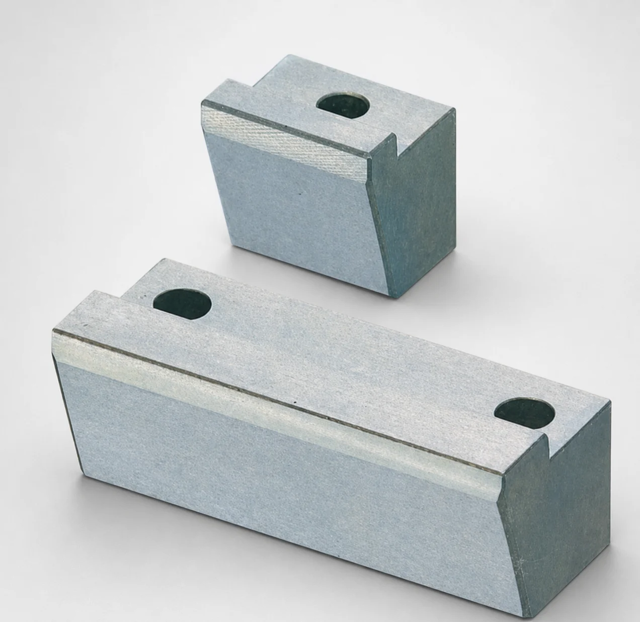
O1 Tool Steel Positioning Locking Blocks with Oil Grooves
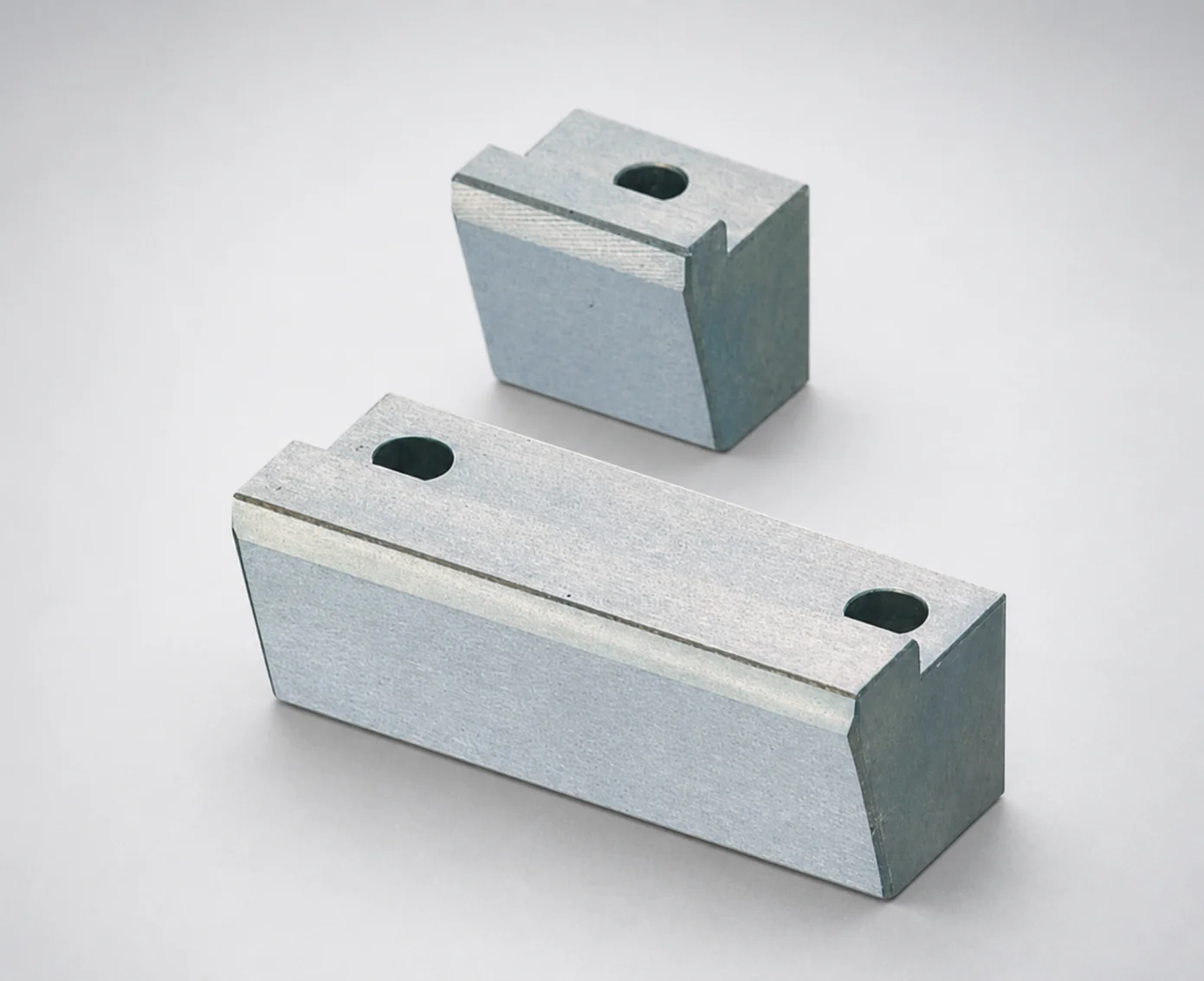
Positioning Locking Blocks Angle Configurable, Oil-Free Options
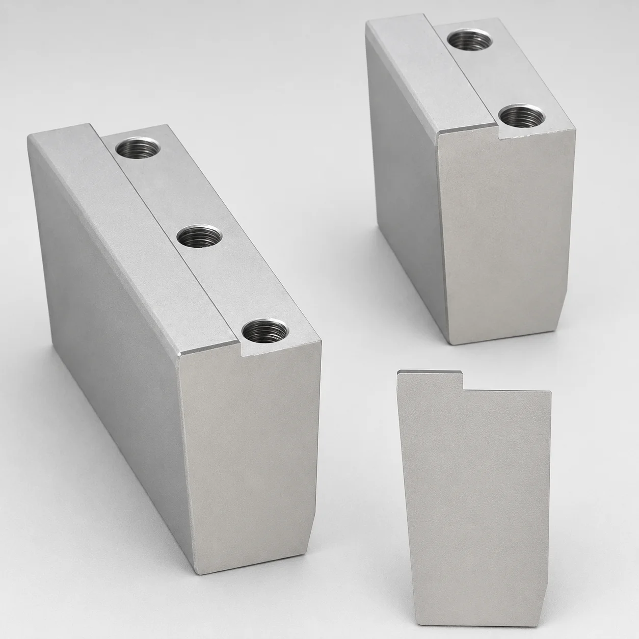
O1 Tool Steel Positioning Locking Blocks - Beveled Edge Bottom (KN)
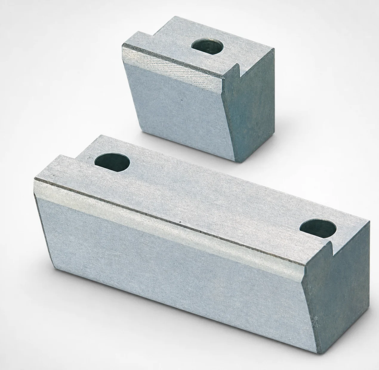
O1 Tool Steel Positioning Locking Blocks - Angle Configurable
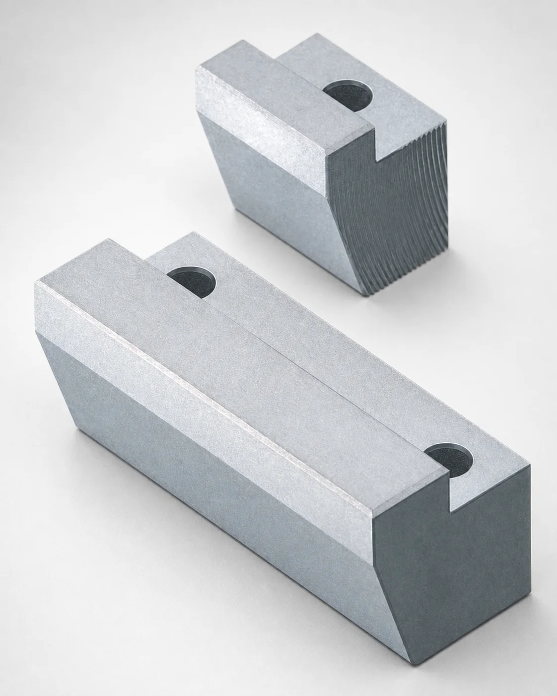
Locking Blocks - Fixed Angle & Inlay Height Configurable
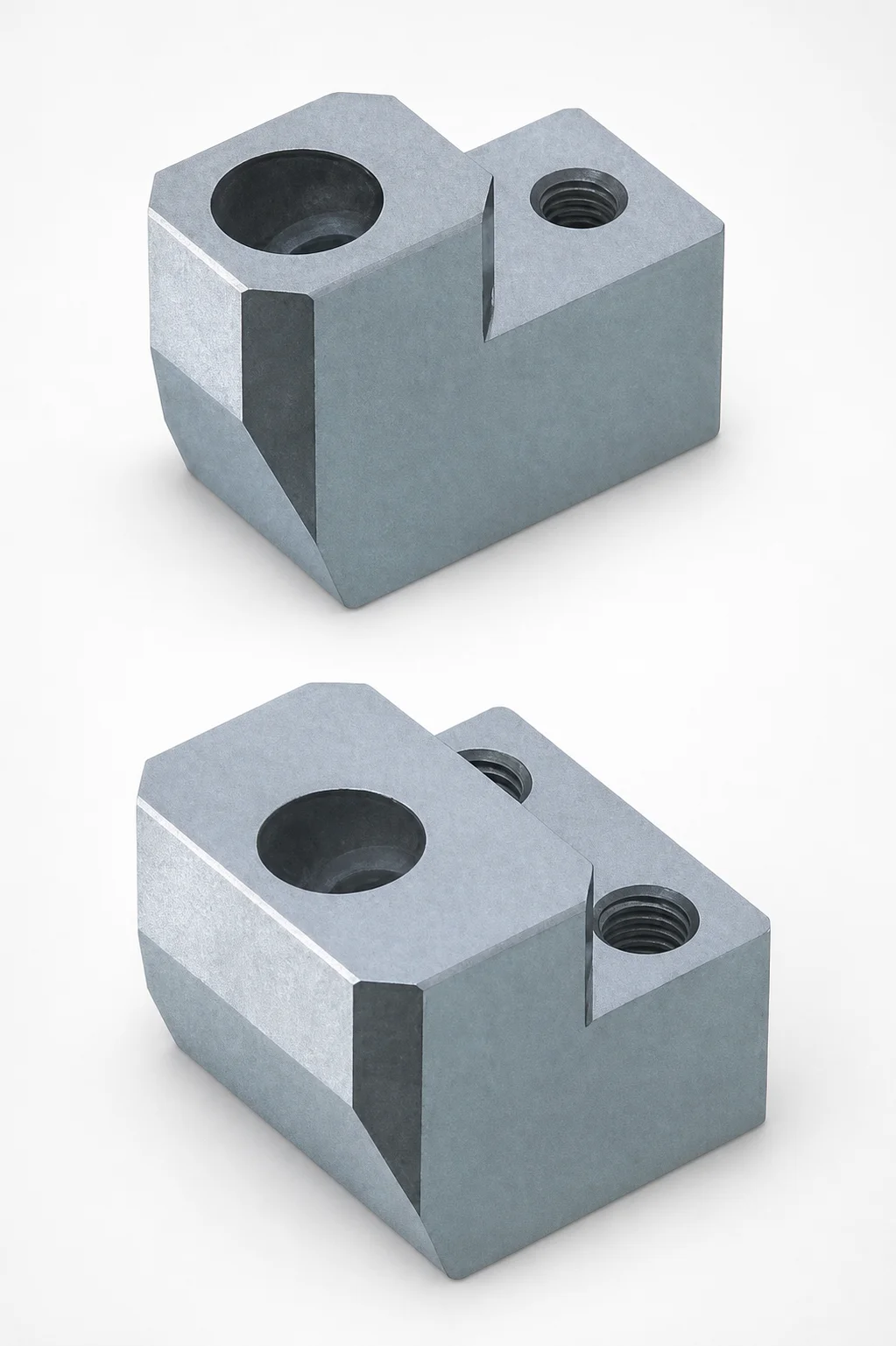
ABPXE Type O1 Tool Steel Positioning Locking Blocks with Angular Pin Hole
Need Custom Specifications?
Our engineering team can help with custom configurations, material selection, and volume pricing.