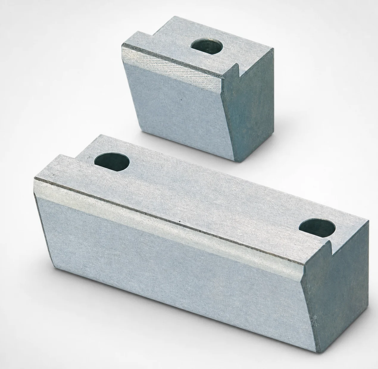
O1 Tool Steel Positioning Locking Blocks - Angle Configurable
Positioning locking blocks (O1 tool steel) with angle configurable locking surfaces are designed to support repeatable mold positioning and positive part location. They use a PL installation style and include an inlay height reference for consistent assembly.
- Angle configurable locking geometry for controlled positioning in tool setups
- O1 tool steel construction with wear-resistant performance for long runs
- Designed for stable plate-to-block mounting with PL installation
- Non-oil groove option supports cleaner wear management in the mold cavity
Specifications
30 configurations available
| Material | Block Height T (mm) | Block Length L (mm) | A/W (Block width) (mm) | G (Angle) (°) | type |
|---|---|---|---|---|---|
| HPM2T | 10 | 20 | 13 ~ 48 | 5 ~ 33 | - |
| HPM2T | 15 | 20 | 13 ~ 58 | 5 ~ 24 | - |
| HPM2T | 20 | 20 | 13 ~ 58 | 5 ~ 18 | - |
| HPM2T | 10 | 25 | 18 ~ 98 | 5 ~ 33 | - |
| HPM2T | 15 | 25 | 18 ~ 108 | 5 ~ 33 | - |
| HPM2T | 20 | 25 | 18 ~ 108 | 5 ~ 26 | - |
| HPM2T | 25 | 25 | 18 ~ 108 | 5 ~ 21 | - |
| HPM2T | 15 | 30 | 23 ~ 128 | 5 ~ 33 | - |
| HPM2T | 20 | 30 | 23 ~ 128 | 5 ~ 31 | - |
| HPM2T | 25 | 30 | 23 ~ 128 | 5 ~ 26 | - |
| HPM2T | 30 | 30 | 23 ~ 128 | 5 ~ 22 | - |
| HPM2T | 25 | 35 | 38 ~ 128 | 5 ~ 28 | - |
| HPM2T | 30 | 35 | 38 ~ 128 | 5 ~ 24 | - |
| HPM2T | 35 | 35 | 38 ~ 128 | 5 ~ 21 | - |
| HPM2T | 40 | 35 | 38 ~ 128 | 5 ~ 18 | - |
| O1 Tool Steel | 10 | 20 | 13 ~ 48 | 5 ~ 33 | - |
| O1 Tool Steel | 15 | 20 | 13 ~ 58 | 5 ~ 24 | - |
| O1 Tool Steel | 20 | 20 | 13 ~ 58 | 5 ~ 18 | - |
| O1 Tool Steel | 10 | 25 | 18 ~ 98 | 5 ~ 33 | - |
| O1 Tool Steel | 15 | 25 | 18 ~ 108 | 5 ~ 33 | - |
| O1 Tool Steel | 20 | 25 | 18 ~ 108 | 5 ~ 26 | - |
| O1 Tool Steel | 25 | 25 | 18 ~ 108 | 5 ~ 21 | - |
| O1 Tool Steel | 15 | 30 | 23 ~ 128 | 5 ~ 33 | - |
| O1 Tool Steel | 20 | 30 | 23 ~ 128 | 5 ~ 31 | - |
| O1 Tool Steel | 25 | 30 | 23 ~ 128 | 5 ~ 26 | - |
| O1 Tool Steel | 30 | 30 | 23 ~ 128 | 5 ~ 22 | - |
| O1 Tool Steel | 25 | 35 | 38 ~ 128 | 5 ~ 28 | - |
| O1 Tool Steel | 30 | 35 | 38 ~ 128 | 5 ~ 24 | - |
| O1 Tool Steel | 35 | 35 | 38 ~ 128 | 5 ~ 21 | - |
| O1 Tool Steel | 40 | 35 | 38 ~ 128 | 5 ~ 18 | - |
Product Guide
Application Scenarios+
Positioning locking blocks with angle-configurable locking surfaces are used in precision injection mold tooling to create repeatable plate-to-plate alignment and positive part location. In automotive connector and housing molds, the controlled locking geometry helps maintain consistent ejector or cavity plate positioning across build cycles, reducing variation that can translate into flash or dimensional drift.
They are also suitable for medical device housings and insert-molding tooling, where assembly repeatability and stable shut-off alignment are essential for tight tolerances. The O1 tool steel construction provides wear-resistant performance for frequent maintenance and reassembly.
For undercut feature molds and cavity/slider plate stacks, the PL installation style supports stable mounting, while the inlay-height reference supports consistent assembly. The angle (5°) configurability is especially useful when your locking surfaces must match a specific mold build geometry without redesigning the entire plate stack.
Material & Process Details+
This component is manufactured from either O1 tool steel or HPM2T, selected to balance wear resistance and toughness for mold plate positioning hardware.
O1 Tool Steel is a high-performance oil-hardening tool steel commonly used for parts that require good wear resistance with manageable impact toughness. After machining, it is typically quenched and tempered to achieve the target hardness; this state is appropriate for maintaining stable locking surfaces under repeated assembly loads.
HPM2T is an air- or improved performance tool steel variant (often selected for higher wear resistance versus conventional tool steels). Compared to O1, HPM2T is typically chosen when you need improved surface durability in the locking area; the trade-off is that your design may require careful attention to toughness and stress management depending on tempering level.
- Key property goal: wear-resistant locking faces for repeatable alignment
- Heat treatment: quenched & tempered (typical for tool-steel locking components)
- Hardness: set via tempering to maintain surface stability while avoiding brittleness
Sizing & Selection Guide+
Correct selection is driven by block height T (10–40 mm), block length L (20, 25, 30, 35 mm), and block width W (A/W ranges depend on width family) in combination with the required locking interface geometry.
Match the block height T to your plate stack spacing so the locking surface engages at the intended inlay height reference during assembly. Choose L based on the available mounting length on the plate/undercut block area; the available discrete options (20/25/30/35 mm) simplify standardization in mold designs.
- Select W (A/W) from the provided ranges: 13–48, 13–58, 18–98, 18–108, 23–128, or 38–128 mm families.
- Use the angle G as specified: 5° to fit the locking surface geometry of the mating component.
- When integrating into core/cavity stacks, allow for machining and assembly clearance so the locking faces seat without binding.
Where your plate-to-block mounting is fixed by the PL installation style, verify that your chosen T/L/W align with fastener clearances and the locating surfaces’ engagement area.
Frequently Asked Questions
What material options are available for these positioning locking blocks, and how do I choose between O1 tool steel and HPM2T?+
The blocks are available in O1 tool steel or HPM2T. Choose O1 when you want reliable wear performance for positioning hardware during repeated mold assembly and maintenance. Choose HPM2T when the application benefits from higher wear durability on the locking surfaces, while still requiring proper tempering to maintain toughness.
How do I select the correct block height T and length L to match my mold plate stack and mounting area?+
Use T (10–40 mm) to match the available spacing so the locking surface engages at the intended inlay-height reference. Select L from the discrete options 20, 25, 30, 35 mm based on the mounting length available on your cavity/core or plate stack. Confirm that your chosen dimensions maintain full contact on the locking interface without causing binding during assembly.
The product lists multiple A/W (block width) ranges—how do I determine the correct W for my design?+
Pick a width family that fits your plate footprint using the provided A/W ranges: 13–48, 13–58, 18–98, 18–108, 23–128, or 38–128 mm. In practice, choose the smallest width that provides the required engagement area while maintaining adequate clearance to surrounding mold features. Verify compatibility with your fastener and machining constraints for stable PL installation.
Why is angle configurability relevant here, and what is the specified locking angle?+
This variant provides an angle-configurable locking surface with the specified G = 5°. Use this value when the mating locking geometry in your plate stack is designed around a 5° seating profile. Selecting a different angle would require matching the mating component geometry to avoid poor engagement or uneven contact.
Are these blocks intended for PL installation, and what does that imply for placement and repeatability?+
Yes, they use a PL installation style, designed for stable positioning between plates and blocks. This installation approach helps maintain consistent assembly alignment, supporting repeatable mold positioning and positive part location. When planning placement, align the block’s T and width W to ensure the locking faces seat correctly during reassembly.
Related Products
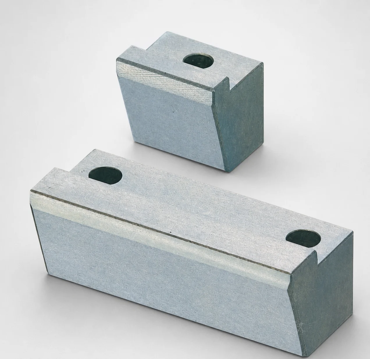
O1 Tool Steel Positioning Locking Blocks with Oil Grooves
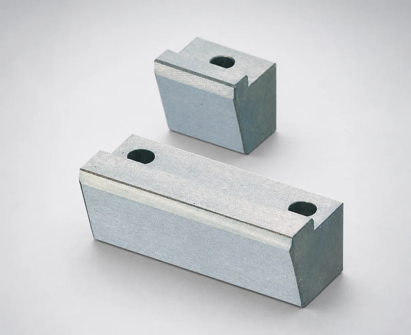
Positioning Locking Blocks Angle Configurable, Oil-Free Options
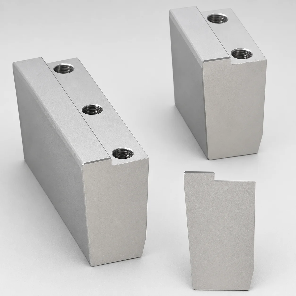
O1 Tool Steel Positioning Locking Blocks - Beveled Edge Bottom (KN)
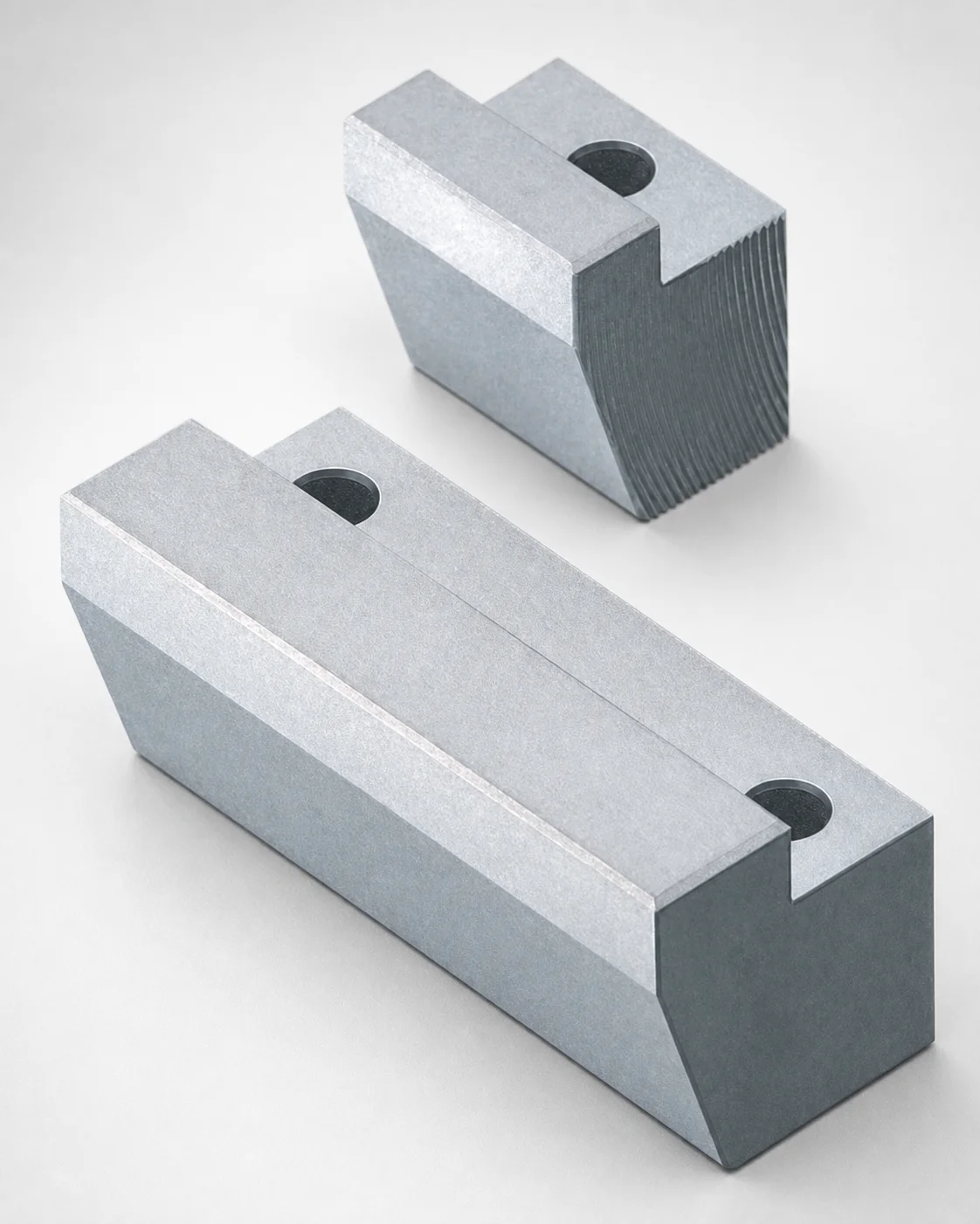
Locking Blocks - Fixed Angle & Inlay Height Configurable
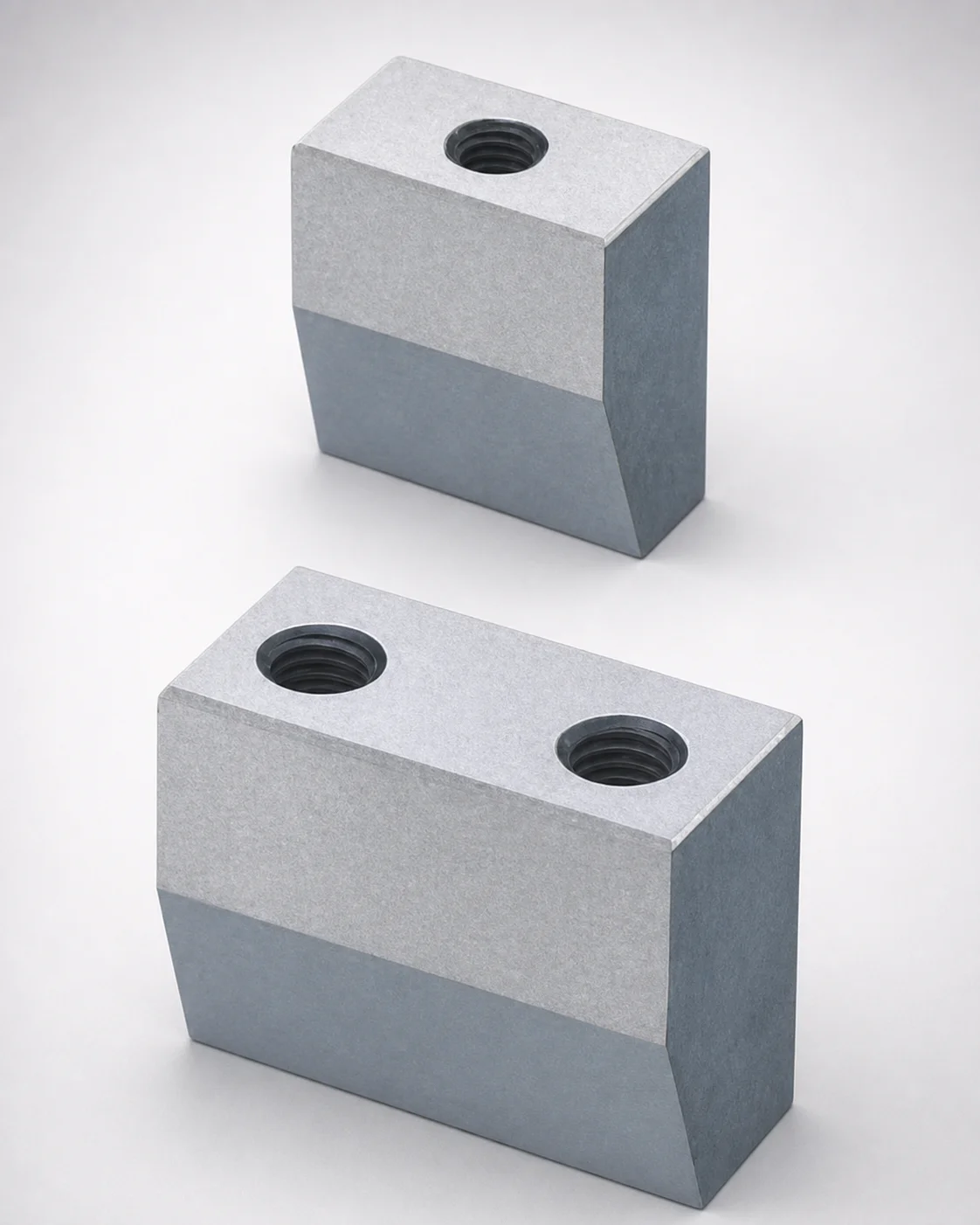
Inlay Type Locking Blocks with Plate Side Setting (Tapped)
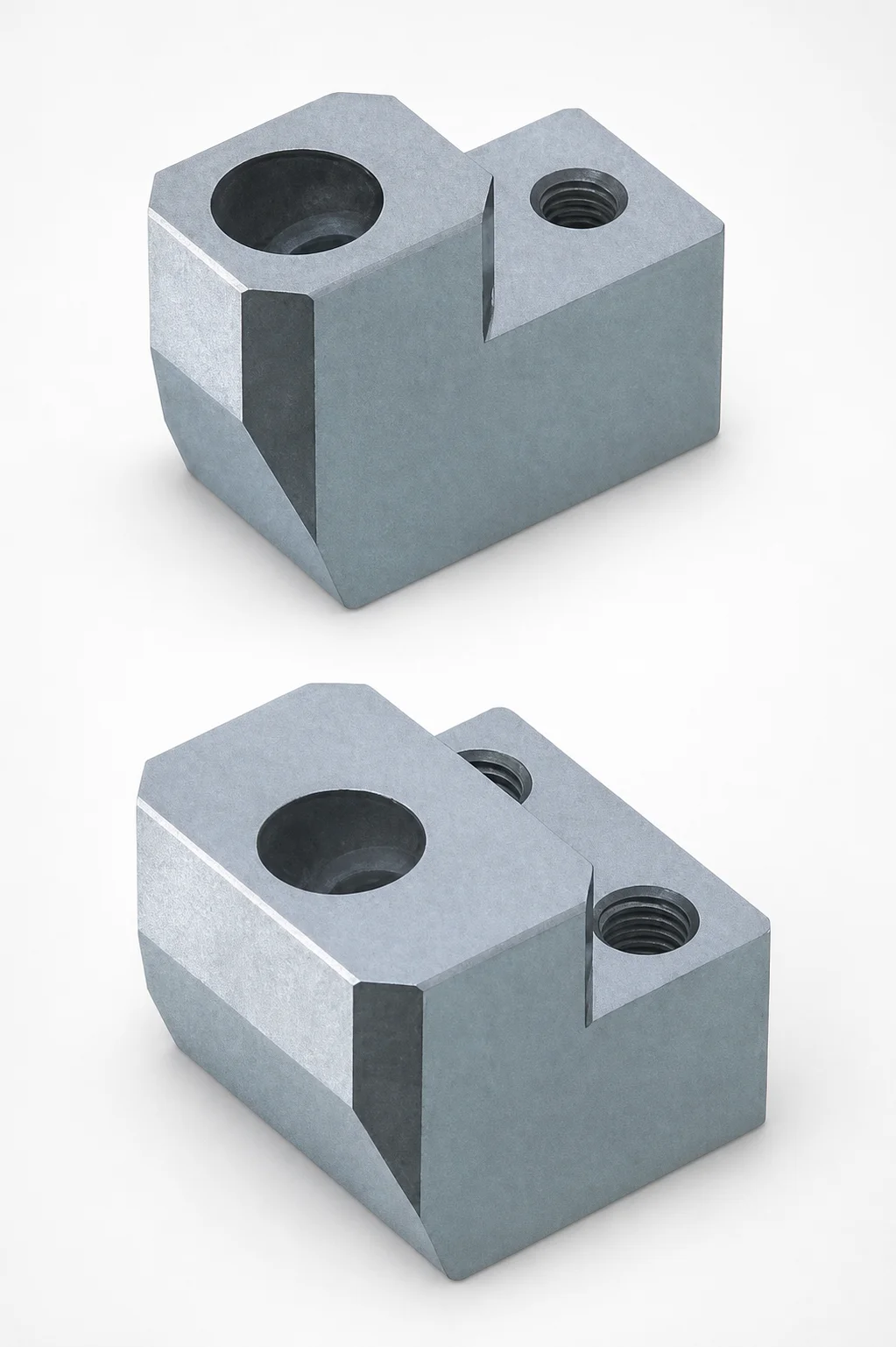
ABPXE Type O1 Tool Steel Positioning Locking Blocks with Angular Pin Hole
Need Custom Specifications?
Our engineering team can help with custom configurations, material selection, and volume pricing.