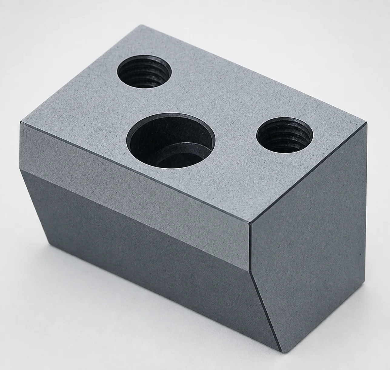
O1 Tool Steel Locking Blocks with Angular Pin Holes
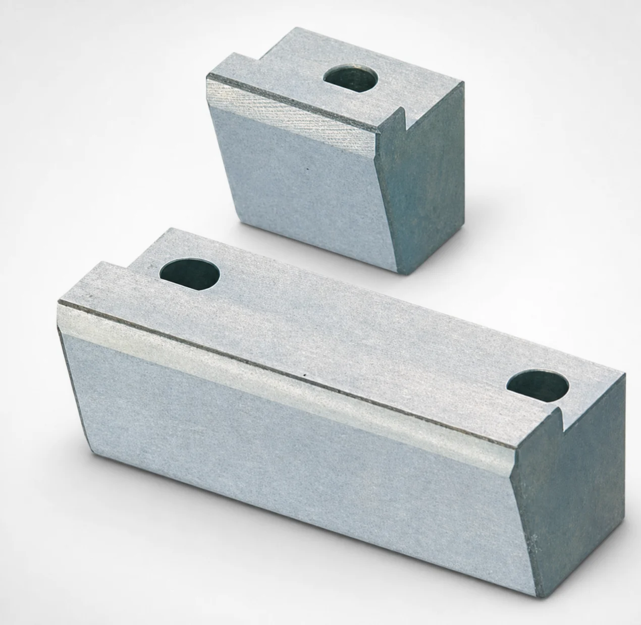
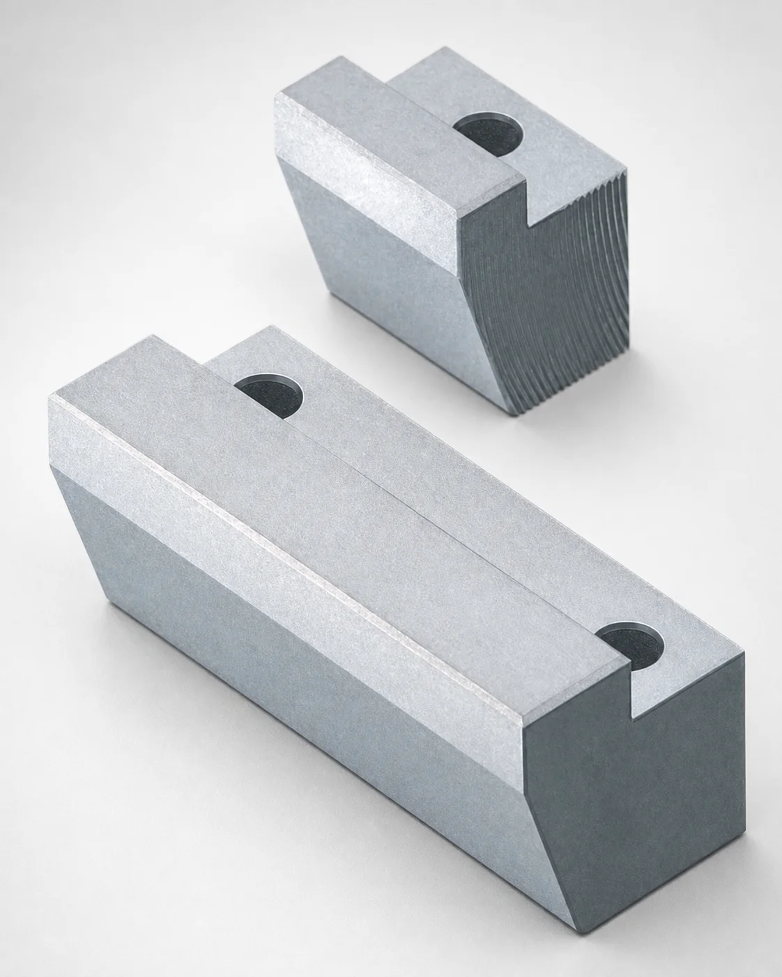
O1 Tool Steel locking blocks with angular pin holes are inlay-type mold components designed for reliable angled positioning and secure fixing from the parting line. The ALBPS type helps maintain consistent location during assembly and operation.
- Includes angular hole for controlled inlay alignment in the mold
- O1 tool steel construction with robust wear performance for tool life
- Inlay type (ALBPS) supports stable mechanical locking at the parting line
- PL installation fits partition-line mounting for straightforward mold integration
Specifications
4 configurations available
| Block Height T (mm) | A/W (Block width) (mm) | H/E (Inlay Part Dimension) (mm) | D (Angular Hole Diameter) (mm) | A (Angle) (°) | G (Angle) (°) | type |
|---|---|---|---|---|---|---|
| 30 ~ 50 | 48 ~ 68 | 10 ~ 40 | 10 | 10 ~ 20 | 12 ~ 25 | - |
| 35 ~ 60 | 48 ~ 78 | 10 ~ 50 | 13 | 10 ~ 20 | 12 ~ 25 | - |
| 35 ~ 60 | 58 ~ 78 | 10 ~ 50 | 16 | 10 ~ 20 | 12 ~ 25 | - |
| 40 ~ 60 | 58 ~ 78 | 10 ~ 50 | 20 | 10 ~ 20 | 12 ~ 25 | - |
Product Guide
Application Scenarios+
Locking blocks with angular pin holes are used in injection mold tooling to achieve repeatable inlay positioning along the parting line. The angular hole enables controlled registration of an inlay insert, reducing the risk of shift during assembly and shot-to-shot cycling.
- Automotive connector and insert molds: Inlay-type locating features help maintain alignment of thin ribs, insulation features, or localized texture inserts that must stay concentric with housings under high clamping repeatability.
- Electronics housings and multi-material overmold tooling: The parting-line mechanical locking supports stable placement of auxiliary cavities or inserts, especially where location accuracy affects ejector-side fit and cosmetic surface continuity.
- General undercut / step features: Using the ALBPS inlay type with PL (parting-line) mounting provides secure fixing from the parting line, while the specified angular alignment geometry (angle ranges) is suited for controlled inlay engagement.
This O1 tool steel variant is appropriate where robust wear performance supports frequent assembly cycles and reliable mechanical locking.
Material & Process Details+
This product is made from O1 tool steel (commonly supplied in an injection-mold component-ready condition). O1 is valued for its good balance of machinability and wear resistance in tooling parts that experience repeated contact and sliding/locating action at the parting line.
- Hardness & wear vs. toughness: Typical O1 applications target a medium-to-high hardness level (often in the ~HRC range used for general-purpose tool steels). Higher hardness improves wear resistance of locating surfaces, but increases sensitivity to impact and edge chipping if shock loads occur.
- Heat treatment state: O1 is generally quenched and tempered to set hardness and toughness for dimensional stability during service.
Compared with higher-alloy wear steels, O1 can offer a more practical toughness-to-wear balance for locking/inlay components that must machine cleanly while still maintaining reliable contact performance.
Sizing & Selection Guide+
Select the locking block by matching its inlay engagement geometry and overall block envelope to the mold’s cavity/core pocket requirements. Use the available ranges for Block Height T (30 ~ 50, 35 ~ 60, 40 ~ 60 mm) and Block width A/W (48 ~ 68, 48 ~ 78, 58 ~ 78 mm) to fit the PL mounting space and ensure sufficient material around the angular hole.
- Choose H/E (10 ~ 40 or 10 ~ 50 mm) to match the required inlay part thickness/engagement depth.
- Select the angular hole diameter D (10, 13, 16, 20 mm) to match the locating pin/inlay feature used for registration.
- Confirm the angular geometry: Angle A is 10 ~ 20° and Angle G is 12 ~ 25° for the mating inlay alignment.
Because dimensions are provided as grouped ranges, treat T, A/W, and H/E as configurable options that must be validated against your drawings for fit and assembly clearance at the parting line.
Frequently Asked Questions
Which angular hole diameter D should I select for the inlay locating pin?+
How do I choose the correct block height T for a parting-line PL mounting pocket?+
What is the difference between H/E options and how does it affect inlay engagement?+
How should I verify angular compatibility when Angle A and Angle G are given as ranges?+
Are T, A/W, and H/E fixed sizes or configurable options for this locking block series?+
Related Products
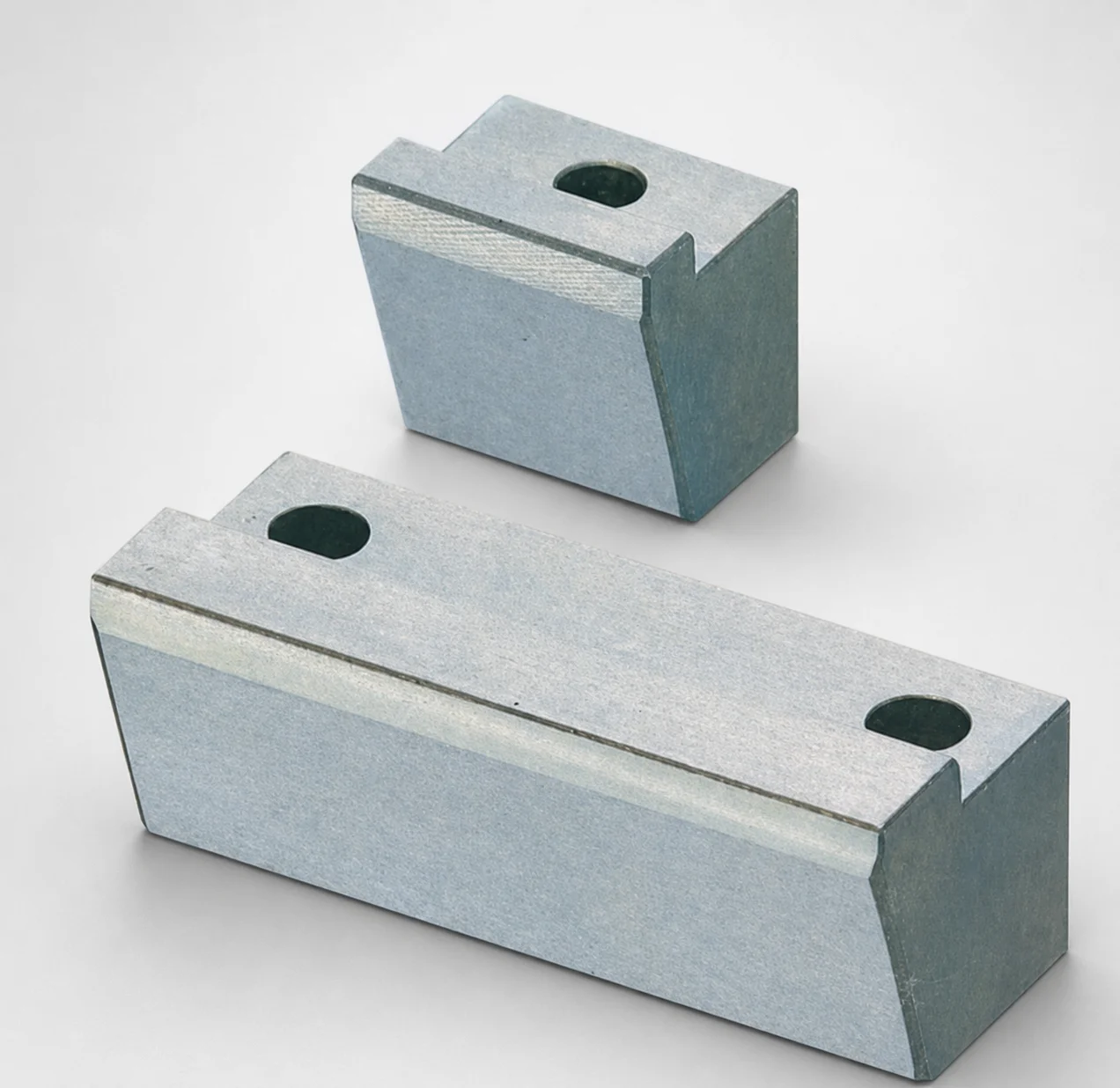
O1 Tool Steel Positioning Locking Blocks with Oil Grooves
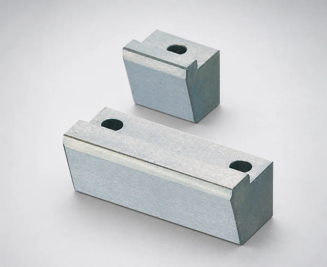
Positioning Locking Blocks Angle Configurable, Oil-Free Options
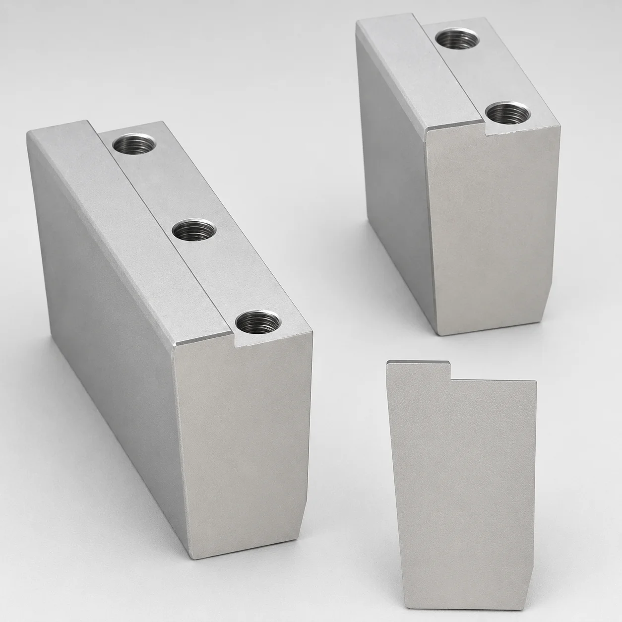
O1 Tool Steel Positioning Locking Blocks - Beveled Edge Bottom (KN)
O1 Tool Steel Positioning Locking Blocks - Angle Configurable
Locking Blocks - Fixed Angle & Inlay Height Configurable
Inlay Type Locking Blocks with Plate Side Setting (Tapped)
Need Custom Specifications?
Our engineering team can help with custom configurations, material selection, and volume pricing.