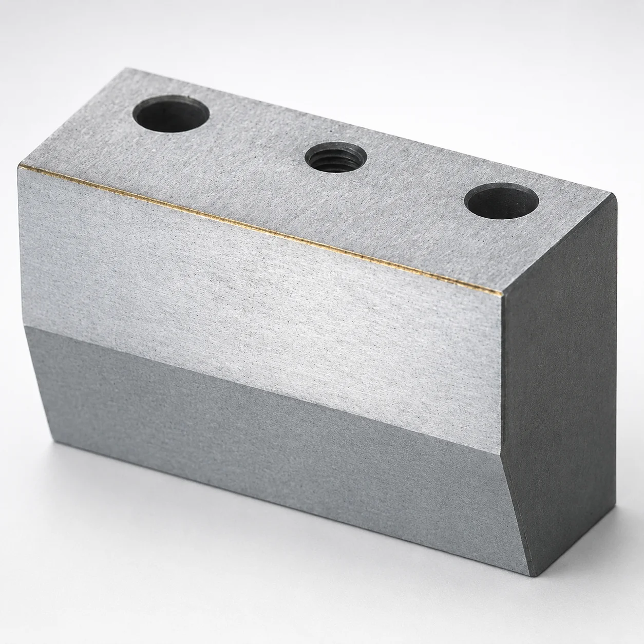
Locking Blocks Inlay Type with PL Installation
Locking Blocks inlay type with PL installation provide positive bolt positioning for reliable mold locking. The non-oil groove design supports clean operation while keeping alignment stable during assembly.
- Inlay type block design ensures consistent engagement for secure locking
- PL installation helps achieve repeatable positioning in tooling
- Non-oil groove option reduces contamination risk compared with oil-groove blocks
- Configurable locking angle range supports compatibility with different mold geometries
Specifications
8 configurations available
| Material | Block Height T (mm) | Block Length L (mm) | A/W (Block width) (mm) | H/E (Inlay Part Dimension) (mm) | G (Angle) (°) | type |
|---|---|---|---|---|---|---|
| HPM2T | 30 | 20 | 33 ~ 58 | 10 ~ 20 | 5 ~ 33 | - |
| HPM2T | 35 | 20 | 33 ~ 58 | 10 ~ 20 | 5 ~ 26 | - |
| HPM2T | 35 | 25 | 38 ~ 78 | 12 ~ 20 | 5 ~ 33 | - |
| HPM2T | 40 | 25 | 38 ~ 78 | 12 ~ 20 | 5 ~ 28 | - |
| O1 Tool Steel | 30 | 20 | 33 ~ 58 | 10 ~ 20 | 5 ~ 33 | - |
| O1 Tool Steel | 35 | 20 | 33 ~ 58 | 10 ~ 20 | 5 ~ 26 | - |
| O1 Tool Steel | 35 | 25 | 38 ~ 78 | 12 ~ 20 | 5 ~ 33 | - |
| O1 Tool Steel | 40 | 25 | 38 ~ 78 | 12 ~ 20 | 5 ~ 28 | - |
Product Guide
Application Scenarios+
Locking blocks with PL installation are used in injection mold base tooling where a subcomponent must be clamped and positioned with high repeatability. In automotive connector molds, these blocks help maintain stable locking geometry across assembly cycles, reducing the risk of bolt drift during mold closing and opening.
- PL installation supports repeatable bolt positioning, which is critical for maintaining consistent undercut engagement.
- Non-oil groove options promote cleaner operation by limiting contamination compared with oil-groove configurations—useful in precision electronics and connector housings.
- Configurable locking angle range (5°–33° / 5°–28° / 5°–26° depending on the variant) allows matching different undercut and mold geometry layouts, improving assembly compatibility.
Choose the specified block height/width and angle range to align with the required inlay dimensions so the locking surfaces engage reliably under clamp load.
Material & Process Details+
This series is offered in HPM2T or O1 tool steel, selected to balance wear resistance and toughness for inlay/undercut locking components. HPM2T (high-speed steel family) is typically used when higher wear resistance and edge stability are required; O1 is commonly selected for good toughness with easier machining depending on tooling strategy.
- Wear vs. toughness trade-off: HPM2T variants generally provide stronger wear performance under repeated sliding contact, while O1 can offer a favorable toughness and machinability balance.
- Heat treatment state: Select a quenched & tempered condition suitable for tool steels in your supplier’s standard process; confirm final target hardness in your molding environment to optimize resistance to micro-wear.
- Hardness (HRC): Final hardness depends on the chosen steel grade and heat treatment recipe; specify the hardness requirement during quotation for consistent locking stability.
Because this product supports precise bolt positioning, material choice should prioritize dimensional stability after heat treatment and sustained wear resistance at the locking interface.
Sizing & Selection Guide+
To select the correct inlay-type locking block, match the block height T, block length L, and block width A/W to the available mounting envelope in your mold base and the undercut/plate layout. The inlay region is defined by H/E (10–20 mm or 12–20 mm depending on configuration), and the locking behavior is governed by angle G.
- Height T: choose 30, 35, or 40 mm to fit the plate stack-up thickness and inlay depth.
- Length L: choose 20 or 25 mm to match the engagement span along the undercut line.
- Width A/W: use ranges 33–58 mm or 38–78 mm depending on your required plate width and bolt spacing.
- Angle G: confirm the variant’s range (5°–33°, 5°–26°, or 5°–28°) to ensure correct geometry engagement.
For fit, verify that the inlay part dimensions (H/E) align with the counter-feature in the mating plate. If your design has critical alignment, request the specified tolerance/fit targets for the locking interface during configuration.
Frequently Asked Questions
Which locking angle range should I select for a specific undercut geometry?+
The series provides multiple G (angle) ranges: 5°–33°, 5°–26°, or 5°–28° depending on the configuration. Select the angle that matches your mating undercut/plate geometry so the locking surfaces engage without over-rotation. During quotation, confirm the exact angle option tied to your chosen T, L, and A/W sizes.
How do I choose block height (T) and inlay part dimension (H/E) together?+
Use T (30, 35, or 40 mm) to fit the mold base stack-up and provide sufficient inlay depth. Then verify the corresponding H/E range (either 10–20 mm or 12–20 mm) matches the inlay pocket depth and geometry in the mating component. This prevents partial engagement that can cause alignment drift over repeated cycles.
What is the practical difference between HPM2T and O1 tool steel for locking blocks?+
The series is available in HPM2T and O1 tool steel. HPM2T is typically chosen to improve wear resistance and interface stability under repeated locking contact, while O1 is commonly selected when you want a strong toughness/machining balance for tool steels. Final performance depends on the selected heat treatment and target hardness (confirm HRC during quotation).
When should I consider the non-oil groove option instead of an oil-groove design?+
This product description notes that a non-oil groove option reduces contamination risk compared with oil-groove blocks. Choose the non-oil groove approach for applications where cleanliness is critical and lubricant contamination could affect assembly or part-quality processes. Validate your maintenance and lubrication strategy to ensure the locking interface remains stable.
How do I ensure repeatable bolt positioning with PL installation?+
PL installation is used to achieve repeatable positioning for the bolt, which directly supports consistent locking performance. In sizing, ensure your chosen block width A/W (33–58 mm or 38–78 mm) and length L (20 or 25 mm) fit the bolt layout and mounting envelope. Confirm that the selected inlay dimensions (H/E) align with the mating plate feature to avoid misalignment at assembly.
Related Products
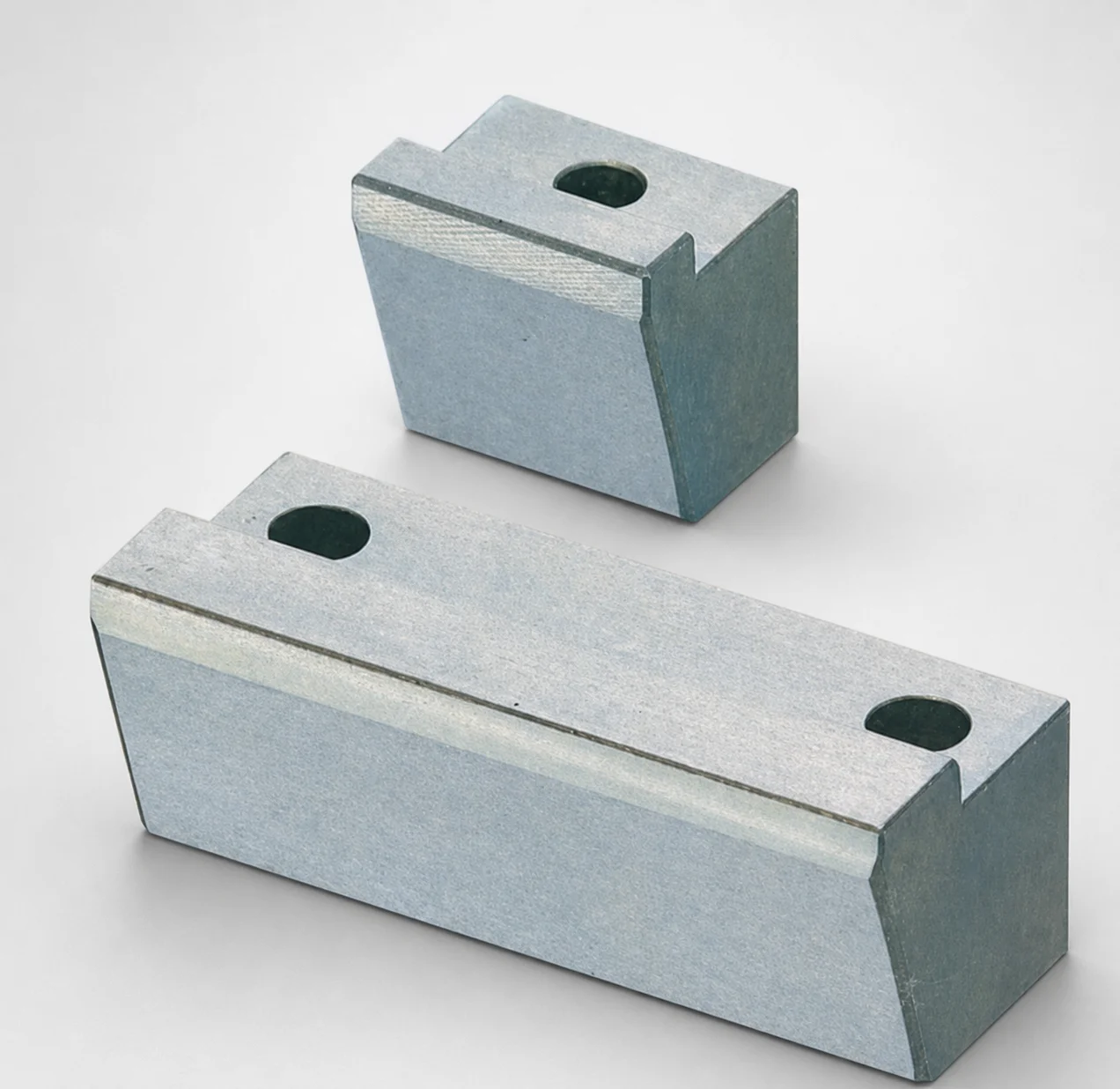
O1 Tool Steel Positioning Locking Blocks with Oil Grooves
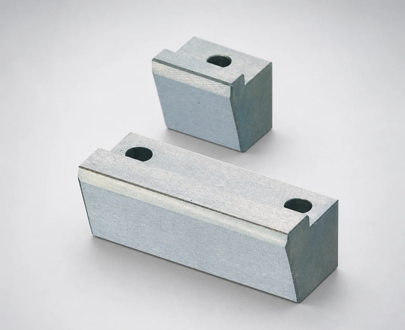
Positioning Locking Blocks Angle Configurable, Oil-Free Options
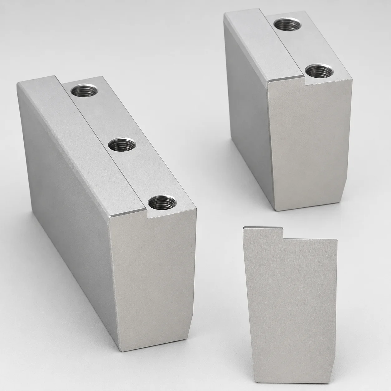
O1 Tool Steel Positioning Locking Blocks - Beveled Edge Bottom (KN)
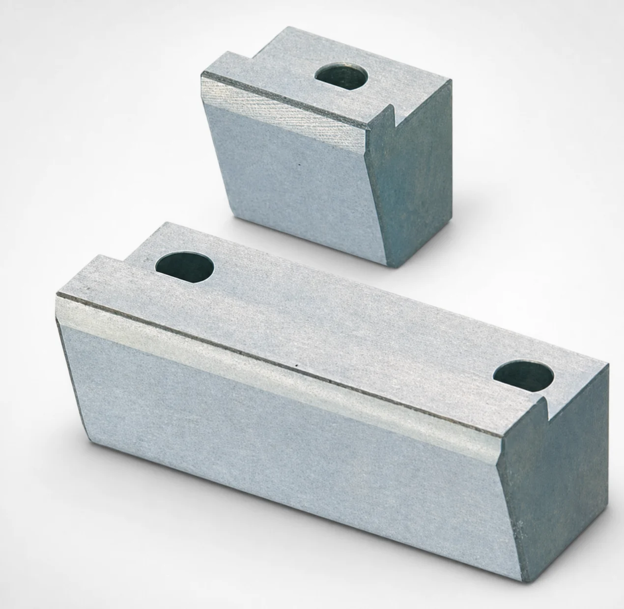
O1 Tool Steel Positioning Locking Blocks - Angle Configurable
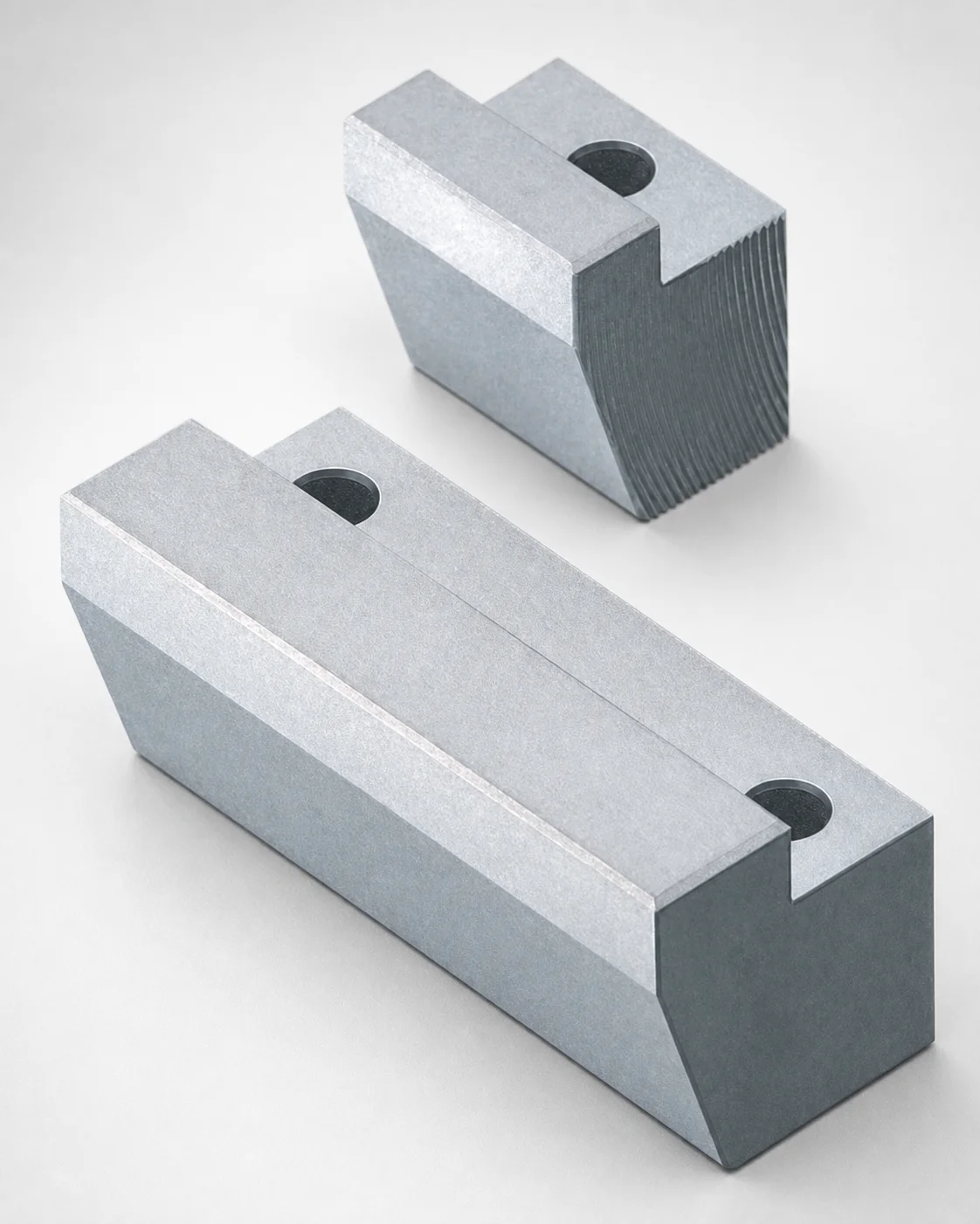
Locking Blocks - Fixed Angle & Inlay Height Configurable
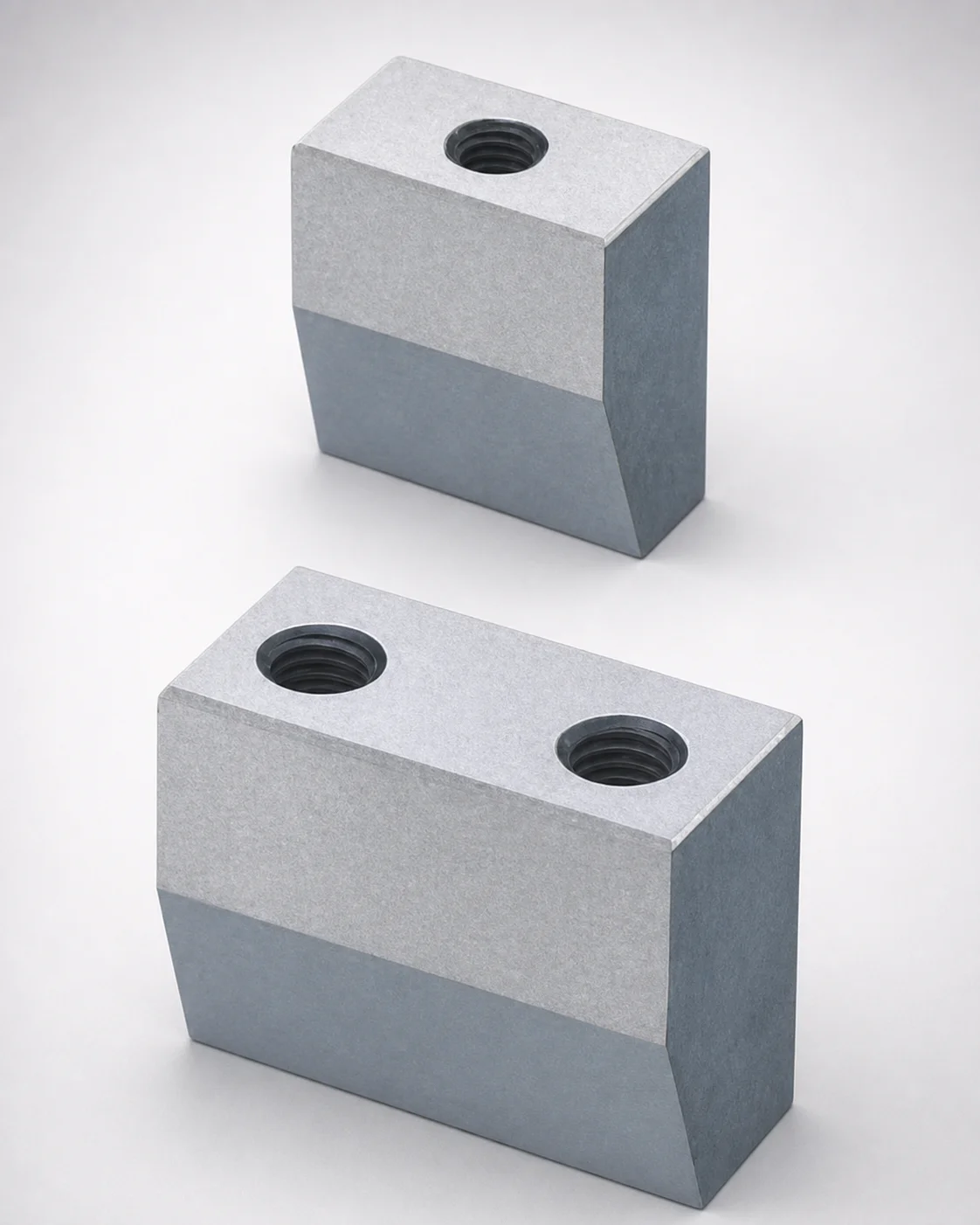
Inlay Type Locking Blocks with Plate Side Setting (Tapped)
Need Custom Specifications?
Our engineering team can help with custom configurations, material selection, and volume pricing.