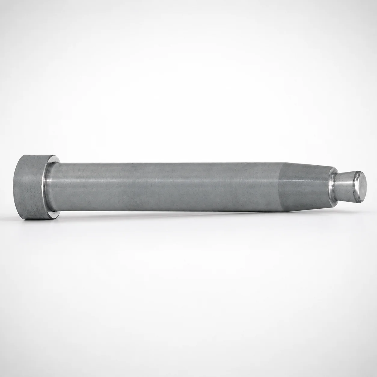
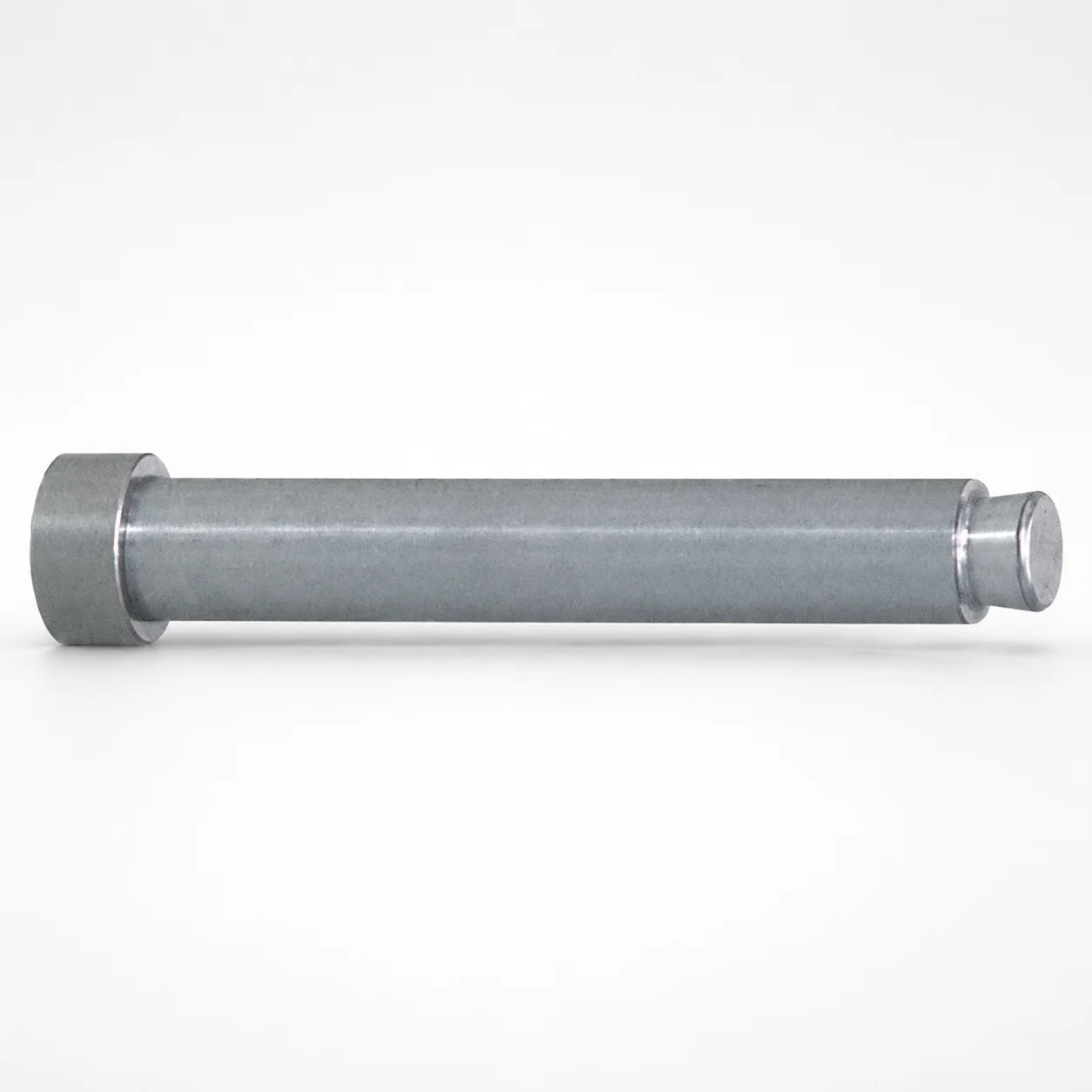
Runner Lock Pins Tapered Shaft Standard Tip
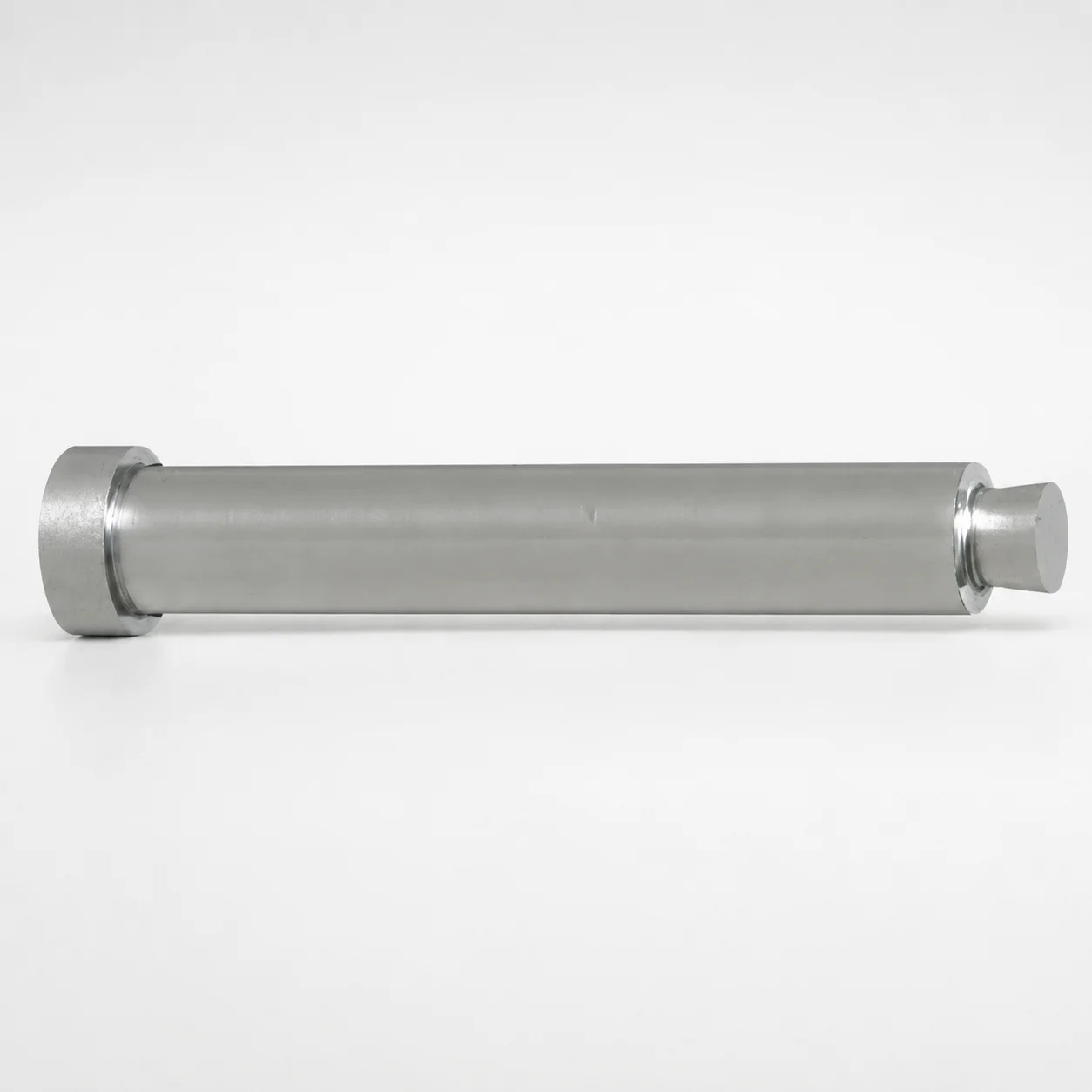
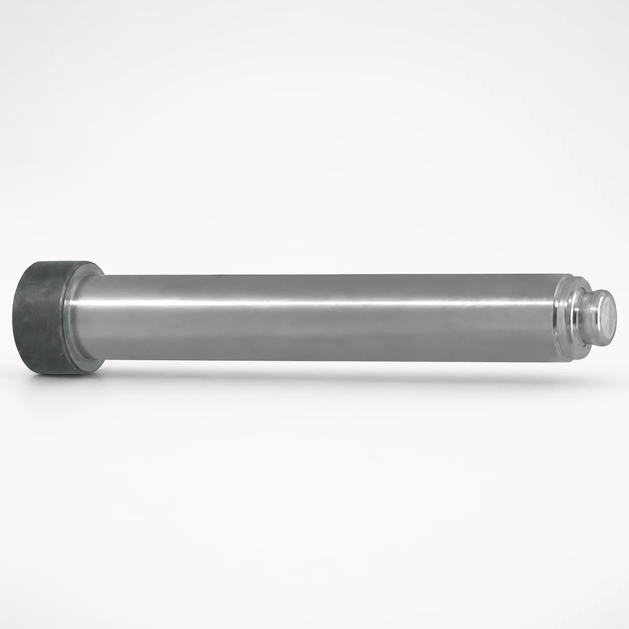
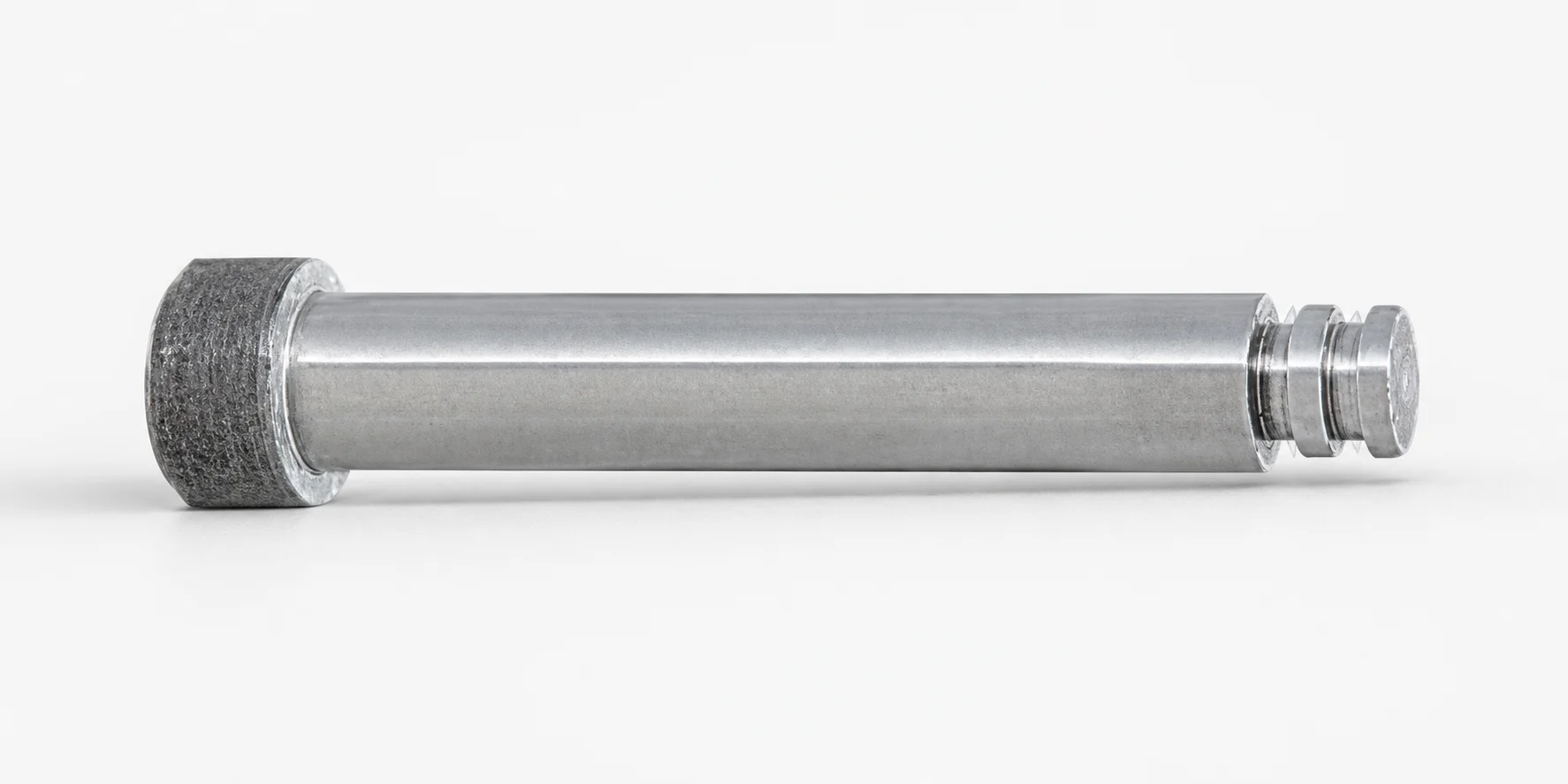
Runner lock pins tapered shaft standard tip are designed to provide reliable runner locking by matching a tapered lead to the mating pocket. The standard tip profile supports consistent positioning and repeatable mold operation.
- Engineered tapered shaft and standard tip for stable runner lock engagement
- Geometry tuned for smooth insertion and secure holding during cycle operation
- Available in multiple lock diameter and head size options for fitment flexibility
- Commonly used in injection molding runner systems to improve alignment accuracy
Specifications
22 configurations available
| Runner Lock Diameter (mm) | Head Diameter | Dimension designation type | L (L dimension) (mm) | B (Tip length) (mm) | G (Taper angle) (°) | P (Tip diameter) (mm) | V (Tip diameter) (mm) | Y (Tip diameter) (mm) | type |
|---|---|---|---|---|---|---|---|---|---|
| 3 | Normal | L/P/Y dimension designation type | 20 ~ 100 | - | - | 0.9 ~ 2.1 | - | 0.8 ~ 2 | - |
| 4 | Normal | L/P/Y dimension designation type | 20 ~ 100 | - | - | 1.1 ~ 2.4 | - | 1 ~ 2.3 | - |
| 5 | Normal | L/P/Y dimension designation type | 20 ~ 100 | - | - | 1.3 ~ 2.8 | - | 1.2 ~ 2.7 | - |
| 6 | Normal | L/P/Y dimension designation type | 25 ~ 100 | - | - | 1.6 ~ 3.3 | - | 1.5 ~ 3.2 | - |
| 8 | Normal | L/P/Y dimension designation type | 25 ~ 100 | - | - | 2.1 ~ 5.2 | - | 2 ~ 5.1 | - |
| 10 | Normal | L/P/Y dimension designation type | 25 ~ 100 | - | - | 2.6 ~ 7 | - | 2.5 ~ 6.9 | - |
| 3 | Normal | L/P/Y/B/V/G dimension designation type | 20 ~ 100 | 0.8 ~ 3 | 5 ~ 10 | 0.9 ~ 2.1 | 2.5 ~ 2.9 | 0.8 ~ 2 | - |
| 4 | Normal | L/P/Y/B/V/G dimension designation type | 20 ~ 100 | 1.3 ~ 3.8 | 5 ~ 10 | 1.1 ~ 2.4 | 3 ~ 3.9 | 1 ~ 2.3 | - |
| 5 | Normal | L/P/Y/B/V/G dimension designation type | 20 ~ 100 | 1.5 ~ 4.5 | 5 ~ 10 | 1.3 ~ 2.8 | 3.5 ~ 4.9 | 1.2 ~ 2.7 | - |
| 6 | Normal | L/P/Y/B/V/G dimension designation type | 25 ~ 150 | 1.5 ~ 4.5 | 5 ~ 10 | 1.6 ~ 3.3 | 4 ~ 5.9 | 1.5 ~ 3.2 | - |
| 8 | Normal | L/P/Y/B/V/G dimension designation type | 25 ~ 150 | 2 ~ 6 | 5 ~ 10 | 2.1 ~ 5.2 | 6 ~ 7.9 | 2 ~ 5.1 | - |
| 10 | Normal | L/P/Y/B/V/G dimension designation type | 25 ~ 150 | 2.5 ~ 7.5 | 5 ~ 10 | 2.6 ~ 7 | 8 ~ 9.9 | 2.5 ~ 6.9 | - |
| 4 | Large | L/P/Y dimension designation type | 20 ~ 100 | - | - | 1.1 ~ 2.4 | - | 1 ~ 2.3 | - |
| 5 | Large | L/P/Y dimension designation type | 20 ~ 100 | - | - | 1.3 ~ 2.8 | - | 1.2 ~ 2.7 | - |
| 6 | Large | L/P/Y dimension designation type | 25 ~ 100 | - | - | 1.6 ~ 3.3 | - | 1.5 ~ 3.2 | - |
| 8 | Large | L/P/Y dimension designation type | 25 ~ 100 | - | - | 2.1 ~ 5.2 | - | 2 ~ 5.1 | - |
| 10 | Large | L/P/Y dimension designation type | 25 ~ 100 | - | - | 2.6 ~ 7 | - | 2.5 ~ 6.9 | - |
| 4 | Large | L/P/Y/B/V/G dimension designation type | 20 ~ 100 | 1.3 ~ 3.8 | 5 ~ 10 | 1.1 ~ 2.4 | 3 ~ 3.9 | 1 ~ 2.3 | - |
| 5 | Large | L/P/Y/B/V/G dimension designation type | 20 ~ 100 | 1.5 ~ 4.5 | 5 ~ 10 | 1.3 ~ 2.8 | 3.5 ~ 4.9 | 1.2 ~ 2.7 | - |
| 6 | Large | L/P/Y/B/V/G dimension designation type | 25 ~ 150 | 1.5 ~ 4.5 | 5 ~ 10 | 1.6 ~ 3.3 | 4 ~ 5.9 | 1.5 ~ 3.2 | - |
| 8 | Large | L/P/Y/B/V/G dimension designation type | 25 ~ 150 | 2 ~ 6 | 5 ~ 10 | 2.1 ~ 5.2 | 6 ~ 7.9 | 2 ~ 5.1 | - |
| 10 | Large | L/P/Y/B/V/G dimension designation type | 25 ~ 150 | 2.5 ~ 7.5 | 5 ~ 10 | 2.6 ~ 7 | 8 ~ 9.9 | 2.5 ~ 6.9 | - |
Product Guide
Application Scenarios+
In injection mold tooling, tapered-shaft runner lock pins are used to positively locate and stabilize runner systems during each opening and closing cycle. The tapered lead promotes smooth entry into the mating pocket, helping align the runner block components before the lock fully seats.
- Automotive connector and small-part runner systems: Use pins with the standard tip geometry to maintain repeatable runner alignment, reducing the risk of intermittent mislock in high-cycle production.
- Packaging and consumer-goods molds: The secure holding behavior supports consistent sprue/runner gating alignment, helping maintain part-to-part dimensional consistency at steady throughput.
- Multicavity hot runner or cold runner assemblies: Select head diameter options (Normal or Large) to match clearance constraints around the runner lock interface and keep engagement reliable across varying runner lock diameters.
Because this variant is built around a specified taper angle range (5–10°) and a standard tip profile, it is suited for molds that need stable alignment with predictable insertion force and locking repeatability.
Material & Process Details+
The provided specifications describe the runner lock geometry (taper angle G: 5–10° and multiple pin/tip diameter options), but no steel grade or heat-treatment state is included in the input data. For this reason, material hardness (e.g., HRC), wear resistance, and toughness trade-offs cannot be stated for this SKU without the manufacturer’s material specification.
In general for runner lock pins, suppliers often use tool steels that can be heat treated for wear resistance at the tip while maintaining sufficient toughness to resist chipping under repeated seating cycles. Typical manufacturing involves machining the tapered shaft and tip, then finishing the contact surfaces for consistent engagement.
- When material grade is confirmed: engineers should verify expected hardness (HRC) and any secondary treatments (e.g., nitriding or quench & tempering) to match the runner system’s wear environment.
- If multiple materials exist: compare hardness vs. toughness to avoid tip wear or deformation that could affect lock stability.
Sizing & Selection Guide+
Select the runner lock pin dimensions by matching both the functional tapered engagement and the mechanical clearance around the head. Start with the Runner Lock Diameter (3, 4, 5, 6, 8, or 10 mm) to ensure the pin fits the mating pocket bore for the runner lock interface.
- Taper and tip engagement: Use the specified taper angle G (5–10°) and the corresponding L (20–100 mm, 25–100 mm, or 25–150 mm) range so the pin reaches the intended seating depth during mold closure.
- Tip geometry matching: Choose B (0.8–3 mm up to 2–6 mm, and 2.5–7.5 mm) and tip diameters (P: 0.9–2.1 / 1.1–2.4 / 1.3–2.8 / 1.6–3.3 / 2.1–5.2 / 2.6–7 mm; V: 2.5–2.9 up to 8–9.9 mm; Y: 0.8–2 up to 2.5–6.9 mm) so the tapered lead and standard tip clear cavities and fully engage the pocket.
- Head clearance: select Normal or Large head diameter based on available space around the runner lock feature.
When integrating into the mold block, verify tolerance stack-up between pocket depth, engagement length, and head clearance to maintain stable locking without excessive insertion force.
Frequently Asked Questions
Which runner lock pin diameter should I select for my runner lock pocket (3, 4, 5, 6, 8, or 10 mm)?+
How do I choose the correct L (pin length) and B (tip length) to achieve full seating during mold closure?+
What taper angle range does this runner lock pin use, and how does it affect alignment?+
How do P, V, and Y tip diameters relate to pocket geometry for the standard tip?+
When should I select the Normal versus Large head diameter option?+
Related Products
Need Custom Specifications?
Our engineering team can help with custom configurations, material selection, and volume pricing.