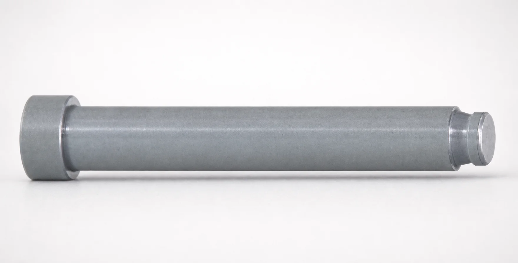
Runner Lock Pins - Straight Shaft, Hard Lock Tip
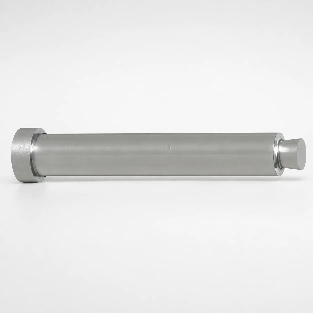
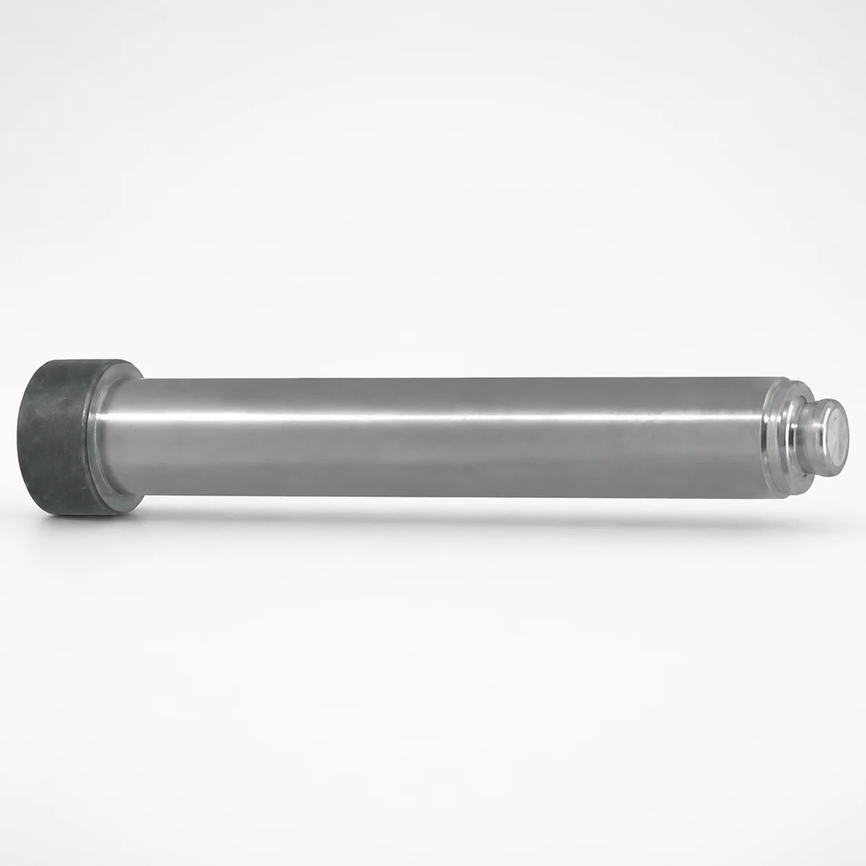
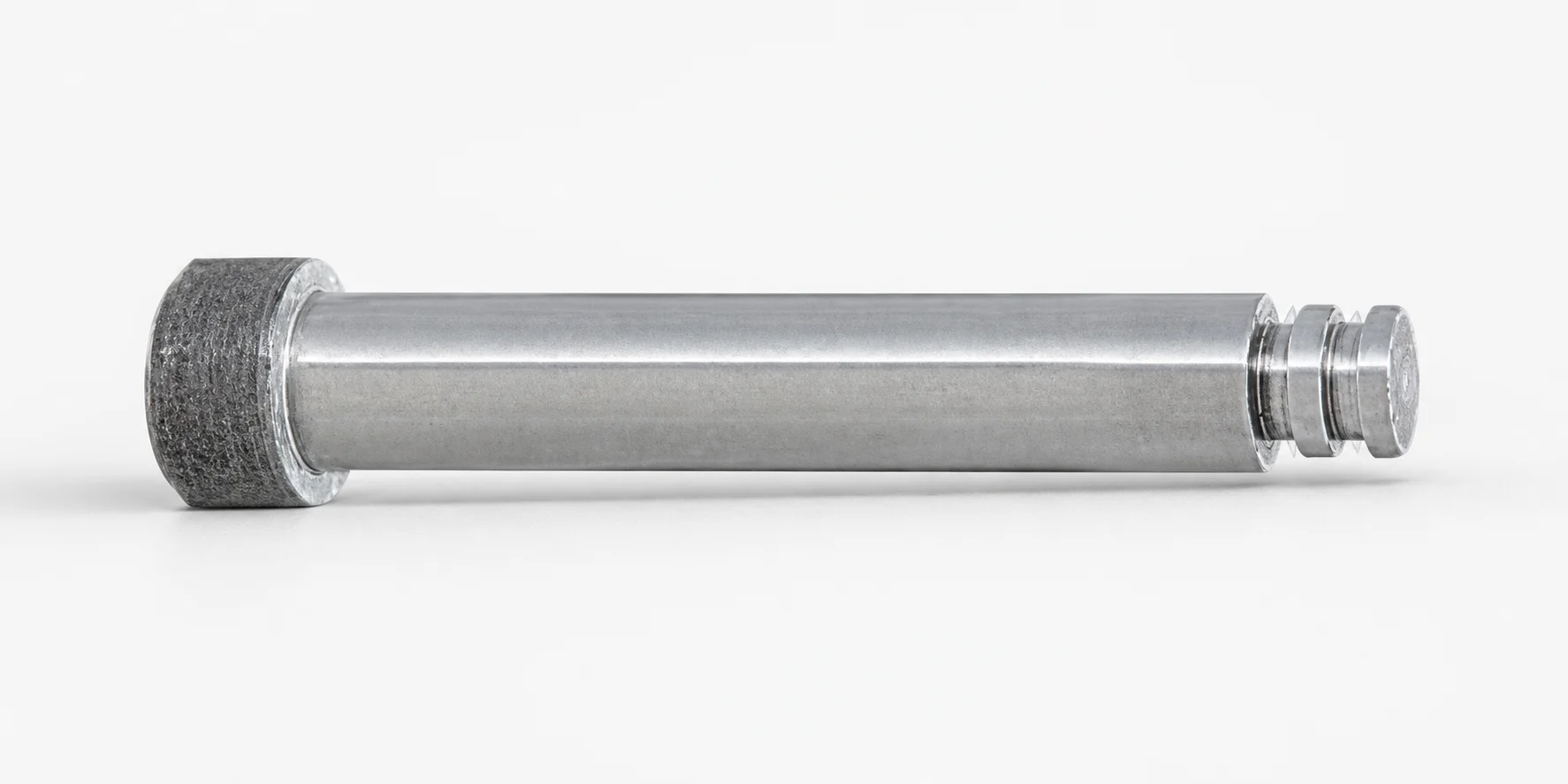
Runner Lock Pins - Straight Shaft, Hard Lock Tip deliver reliable runner control by using a straight-shaft form with a hardened locking tip. This design helps maintain stable positioning under repeated mold cycles for consistent assembly.
- Straight shaft with hard lock tip geometry for dependable retention
- Hardened lock tip construction supports wear resistance in tooling use
- Compatible with a range of runner lock diameters for flexible fit selection
- Commonly used in injection molding runner alignment and lock positioning applications
Specifications
84 configurations available
| Runner Lock Diameter (mm) | Head Diameter | Dimension designation type | L (L dimension) (mm) | B (Tip length) (mm) | E (Tip width) (mm) | F (Tip diameter) (mm) | P (Tip diameter) (mm) | Y (Tip diameter) (mm) | type |
|---|---|---|---|---|---|---|---|---|---|
| 2 | Normal | L dimension selection type | 15 | - | - | - | - | - | - |
| 2 | Normal | L dimension selection type | 20 | - | - | - | - | - | - |
| 2 | Normal | L dimension selection type | 25 | - | - | - | - | - | - |
| 2 | Normal | L dimension selection type | 30 | - | - | - | - | - | - |
| 2 | Normal | L dimension selection type | 35 | - | - | - | - | - | - |
| 2 | Normal | L dimension selection type | 40 | - | - | - | - | - | - |
| 3 | Normal | L dimension selection type | 15 | - | - | - | - | - | - |
| 3 | Normal | L dimension selection type | 20 | - | - | - | - | - | - |
| 3 | Normal | L dimension selection type | 25 | - | - | - | - | - | - |
| 3 | Normal | L dimension selection type | 30 | - | - | - | - | - | - |
| 3 | Normal | L dimension selection type | 35 | - | - | - | - | - | - |
| 3 | Normal | L dimension selection type | 40 | - | - | - | - | - | - |
| 3 | Normal | L dimension selection type | 45 | - | - | - | - | - | - |
| 3 | Normal | L dimension selection type | 50 | - | - | - | - | - | - |
| 4 | Normal | L dimension selection type | 20 | - | - | - | - | - | - |
| 4 | Normal | L dimension selection type | 25 | - | - | - | - | - | - |
| 4 | Normal | L dimension selection type | 30 | - | - | - | - | - | - |
| 4 | Normal | L dimension selection type | 35 | - | - | - | - | - | - |
| 4 | Normal | L dimension selection type | 40 | - | - | - | - | - | - |
| 4 | Normal | L dimension selection type | 45 | - | - | - | - | - | - |
| 4 | Normal | L dimension selection type | 50 | - | - | - | - | - | - |
| 4 | Normal | L dimension selection type | 60 | - | - | - | - | - | - |
| 4 | Normal | L dimension selection type | 70 | - | - | - | - | - | - |
| 4 | Normal | L dimension selection type | 80 | - | - | - | - | - | - |
| 5 | Normal | L dimension selection type | 20 | - | - | - | - | - | - |
| 5 | Normal | L dimension selection type | 25 | - | - | - | - | - | - |
| 5 | Normal | L dimension selection type | 30 | - | - | - | - | - | - |
| 5 | Normal | L dimension selection type | 35 | - | - | - | - | - | - |
| 5 | Normal | L dimension selection type | 40 | - | - | - | - | - | - |
| 5 | Normal | L dimension selection type | 45 | - | - | - | - | - | - |
| 5 | Normal | L dimension selection type | 50 | - | - | - | - | - | - |
| 5 | Normal | L dimension selection type | 60 | - | - | - | - | - | - |
| 5 | Normal | L dimension selection type | 70 | - | - | - | - | - | - |
| 5 | Normal | L dimension selection type | 80 | - | - | - | - | - | - |
| 6 | Normal | L dimension selection type | 30 | - | - | - | - | - | - |
| 6 | Normal | L dimension selection type | 35 | - | - | - | - | - | - |
| 6 | Normal | L dimension selection type | 40 | - | - | - | - | - | - |
| 6 | Normal | L dimension selection type | 45 | - | - | - | - | - | - |
| 6 | Normal | L dimension selection type | 50 | - | - | - | - | - | - |
| 6 | Normal | L dimension selection type | 60 | - | - | - | - | - | - |
| 6 | Normal | L dimension selection type | 70 | - | - | - | - | - | - |
| 6 | Normal | L dimension selection type | 80 | - | - | - | - | - | - |
| 8 | Normal | L dimension selection type | 30 | - | - | - | - | - | - |
| 8 | Normal | L dimension selection type | 35 | - | - | - | - | - | - |
| 8 | Normal | L dimension selection type | 40 | - | - | - | - | - | - |
| 8 | Normal | L dimension selection type | 45 | - | - | - | - | - | - |
| 8 | Normal | L dimension selection type | 50 | - | - | - | - | - | - |
| 8 | Normal | L dimension selection type | 60 | - | - | - | - | - | - |
| 8 | Normal | L dimension selection type | 70 | - | - | - | - | - | - |
| 8 | Normal | L dimension selection type | 80 | - | - | - | - | - | - |
Product Guide
Application Scenarios+
These straight-shaft runner lock pins with a hardened lock tip are used in injection mold tooling to control runner alignment between mold halves and prevent positional drift during repeated cycles.
- Automotive and appliance runner systems: Fit the pins into matching lock positions to maintain consistent runner-to-gate geometry, improving part-to-part repeatability even with high clamp load cycles. The hard lock tip design supports retention under wear.
- Connector and electrical housing molds: Use the pins to ensure stable runner location during assembly and disassembly, helping avoid misalignment that can affect flow balance and cosmetic consistency.
- Multi-cavity molds: Select appropriate lock diameter and L length to match cavity layout. The straight-shaft form supports predictable seating depth, while the hardened tip improves long-term locking behavior.
With a runner lock diameter range of 2–10 mm and selectable L (10–80 mm) lengths, this variant is suited for precise runner location across many runner component sizes.
Material & Process Details+
The provided specifications focus on geometry and fit ranges; a specific steel grade, hardness (HRC), and heat-treatment process are not included in the data. For a runner lock pin intended for a hard lock function, the lock tip is typically engineered to deliver improved wear resistance and stable retention in molding environments.
- Heat treatment (general for hard lock tips): Hardened lock-tip construction is used to increase surface wear resistance at the contact interface, while the pin body can be optimized for acceptable toughness and handling.
- Property trade-offs: Higher tip hardness improves wear resistance, but excessive brittleness can reduce robustness against chipping. Proper selection balances retention performance with durability under repetitive lock engagement.
- Material comparison: If multiple material options exist for the same geometry, select based on the required wear life versus impact/toughness needs. Confirm the exact grade and HRC with the manufacturer before final design freeze.
For this SKU, use the stated hardened lock tip intent and verify the exact material grade/HRC for your production conditions.
Sizing & Selection Guide+
Select the runner lock pin size by matching three key interface dimensions to your mold’s runner lock features: runner lock diameter, L length, and the tip geometry (B/E/F or equivalent design designation).
- Runner Lock Diameter: Choose a diameter in the 2–10 mm range that matches the mating hole/boss in the mold base.
- L dimension (shaft length): Use L = 10–80 mm to achieve the required seating depth and engagement length inside the assembled mold.
- Tip geometry: Select B (tip length) and E (tip width) from the available ranges B: 1.5–3 to 3.8–7.5 mm, E: 0.5–1.5 to 1.3–3.8 mm. Confirm F, P, or Y (tip diameters/widths) using the available ranges: F 0.8–2.5 mm, P 0.9–3 mm, Y 0.8–2.5 mm.
Because the product includes multiple dimension designation types (L, L/P/Y/F, L/P/Y/F/B/E, L/P/Y/F/B/E variants), match your design drawing callout to the correct designation type. For final fit, align with your mold tolerances and allowance on the mating lock surfaces to ensure repeatable locking without interference.
Frequently Asked Questions
Which runner lock diameter should I select for a specific mold lock hole size?+
How do I determine the correct L length for runner alignment and retention?+
What tip dimensions (B/E/F/P/Y) control locking performance in the mold?+
What does “hard lock tip” imply for wear and retention in runner tooling?+
How do dimension designation types affect my selection (L vs L/P/Y/F vs L/P/Y/F/B/E)?+
Related Products
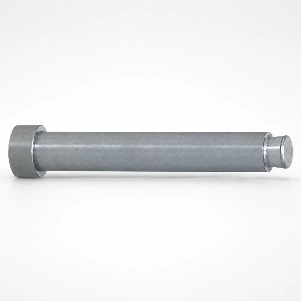
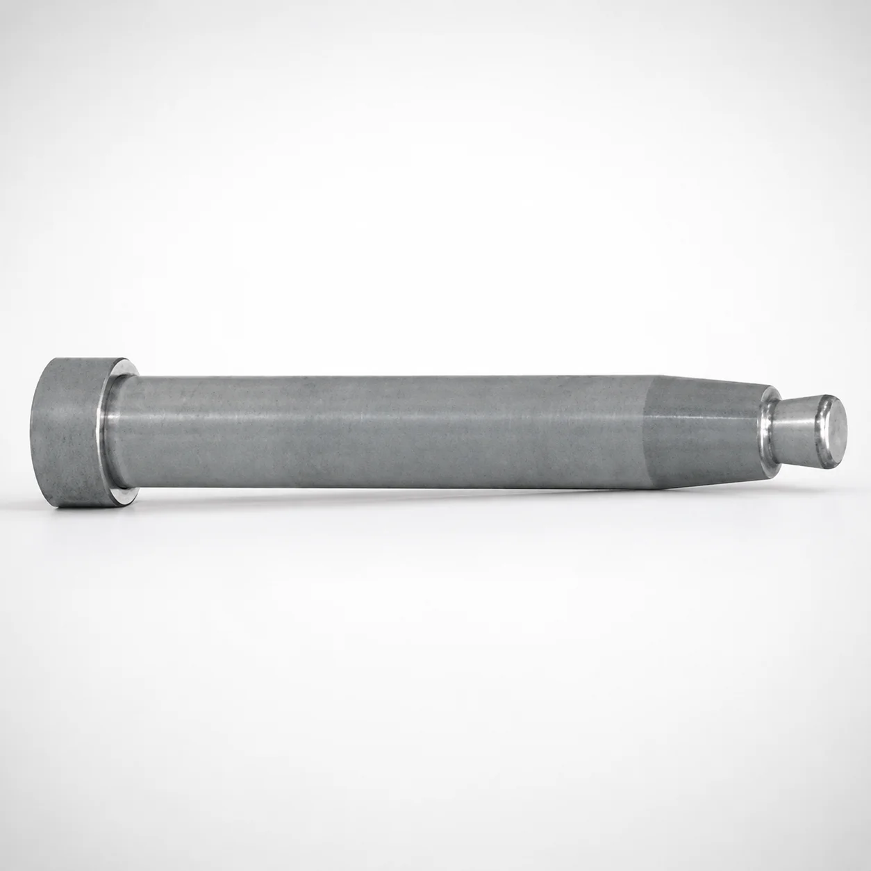
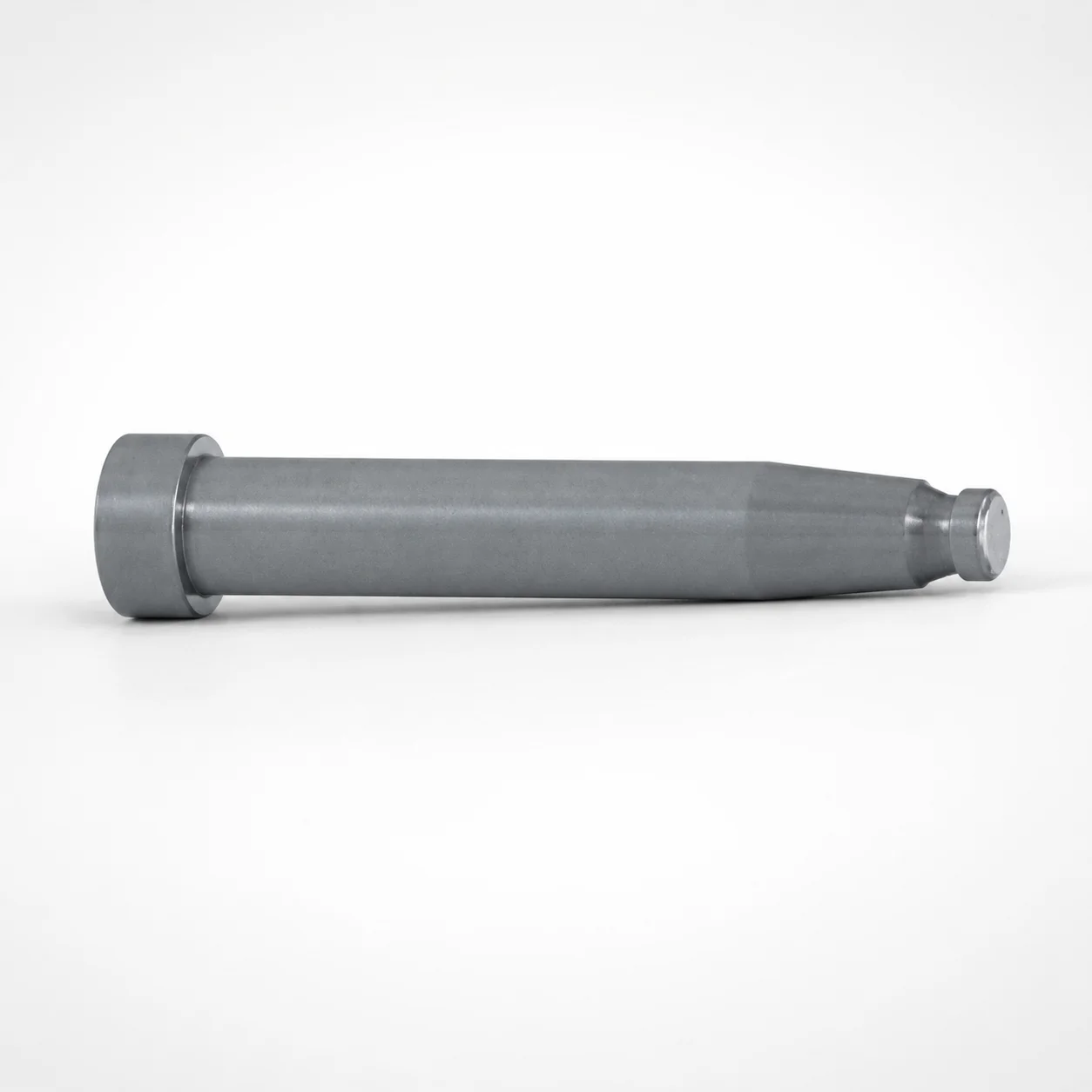
Need Custom Specifications?
Our engineering team can help with custom configurations, material selection, and volume pricing.