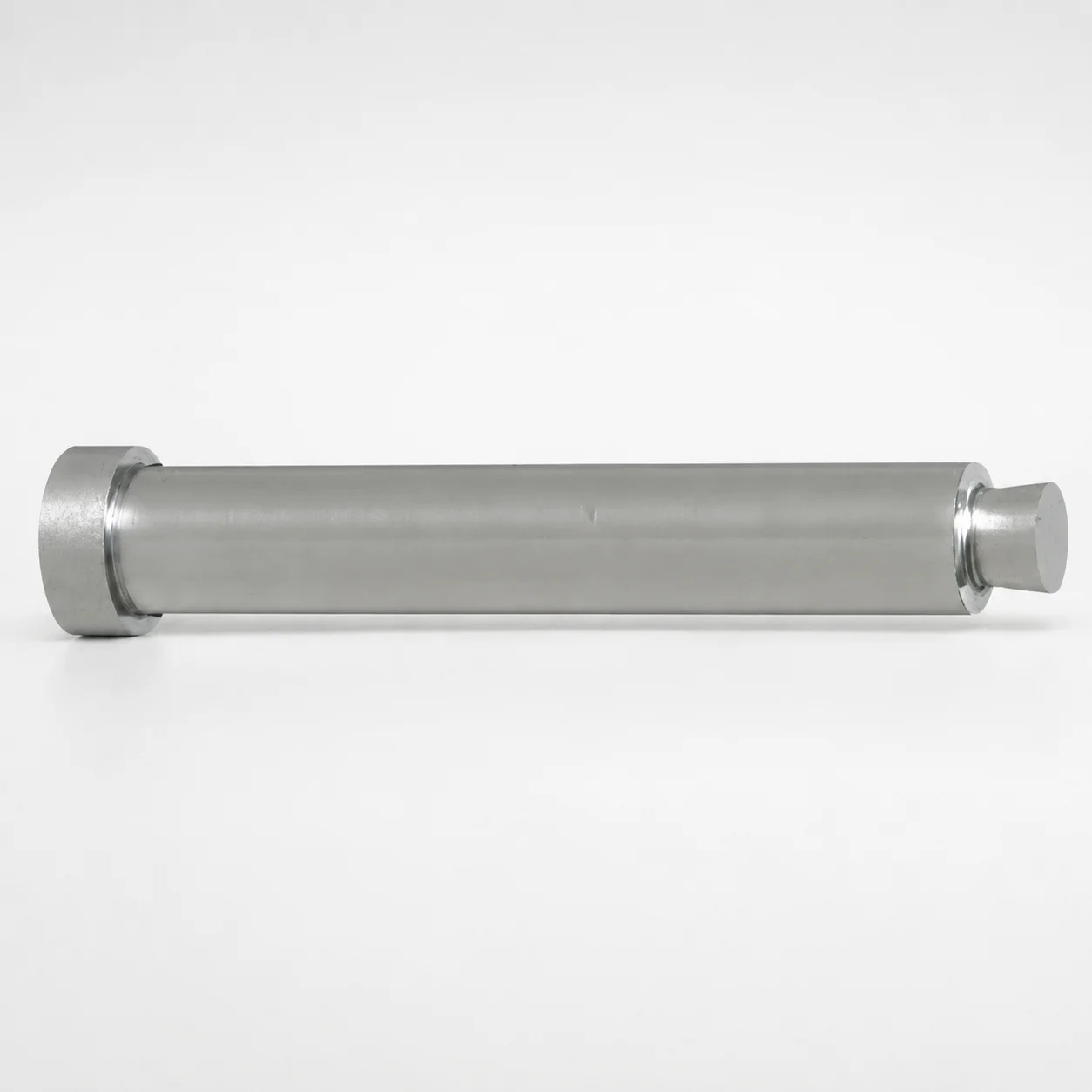
Runner Lock Pins Straight Edge Tip
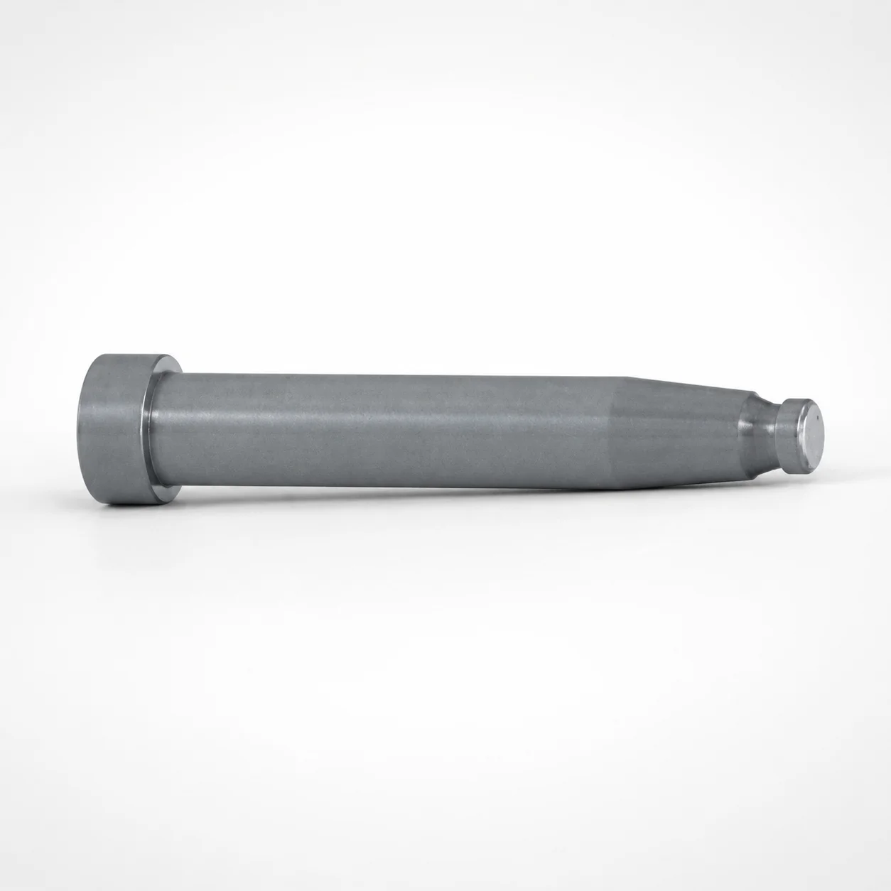
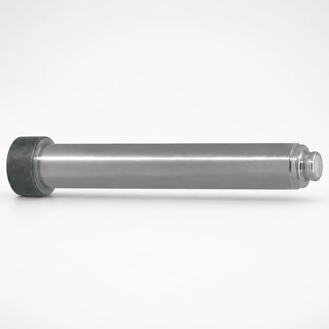
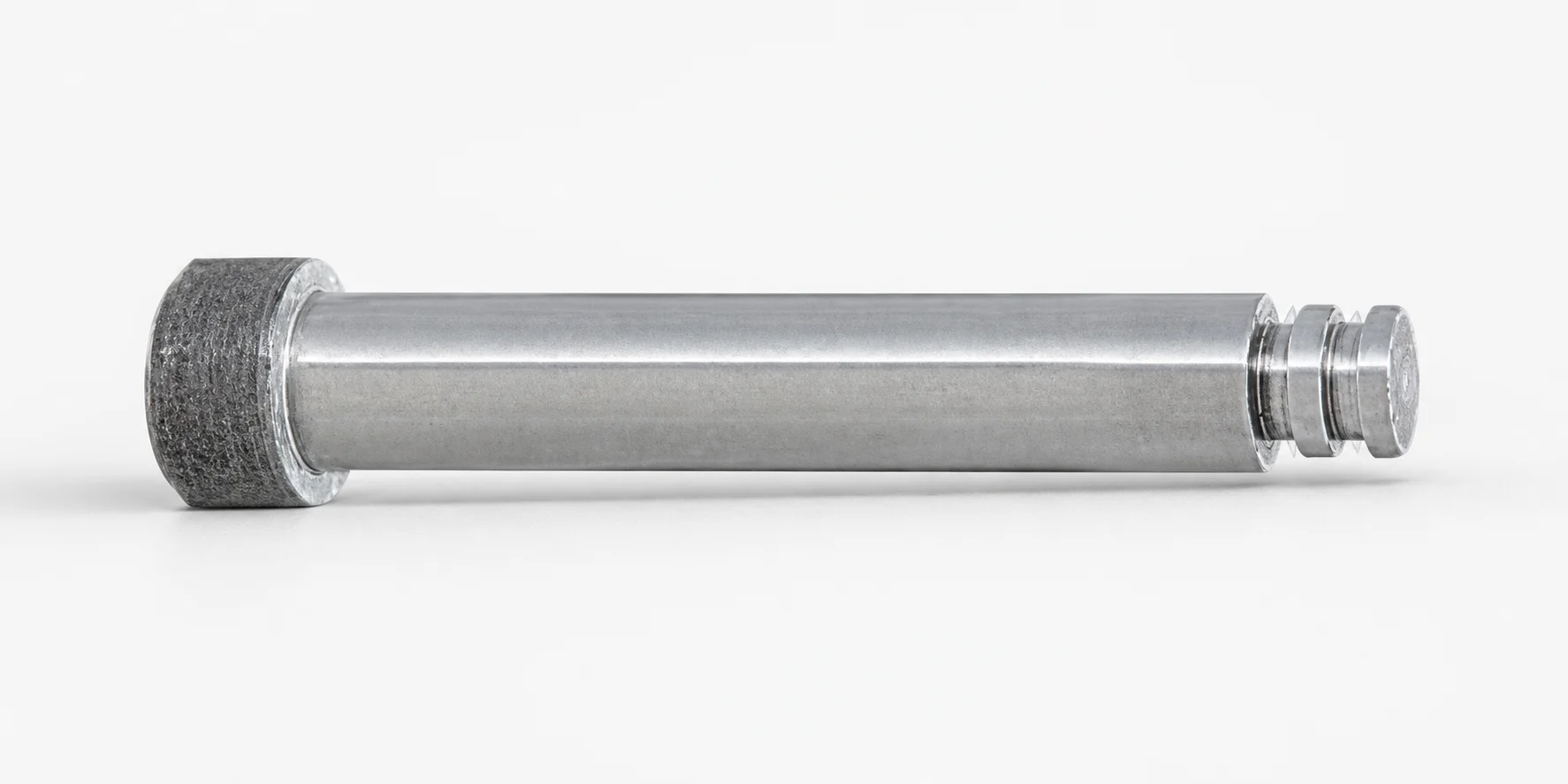
Runner lock pins straight edge tip provide a reliable locking interface for runner positioning and alignment in injection tooling. The straight tip matching shape helps maintain consistent assembly repeatability during production.
- Straight tip edge geometry for dependable runner locking
- Direct fit with straight shaft runner lock pin design
- Supports multiple runner lock diameter options for tooling compatibility
- Commonly used in runner systems for stable mold operation
Specifications
12 configurations available
| Runner Lock Diameter (mm) | Dimension designation type | L (L dimension) (mm) | B (Tip length) (mm) | P (Tip diameter) (mm) | Y (Tip diameter) (mm) | type |
|---|---|---|---|---|---|---|
| 2 | L/P/Y dimension designation type | 10 ~ 100 | - | 0.9 ~ 1.9 | 0.8 ~ 1.8 | - |
| 3 | L/P/Y dimension designation type | 10 ~ 100 | - | 0.9 ~ 2.9 | 0.8 ~ 2.8 | - |
| 4 | L/P/Y dimension designation type | 10 ~ 100 | - | 1.1 ~ 3.9 | 1 ~ 3.8 | - |
| 5 | L/P/Y dimension designation type | 10 ~ 100 | - | 1.3 ~ 4.9 | 1.2 ~ 4.8 | - |
| 6 | L/P/Y dimension designation type | 15 ~ 100 | - | 1.6 ~ 5.9 | 1.5 ~ 5.8 | - |
| 8 | L/P/Y dimension designation type | 15 ~ 100 | - | 2.1 ~ 7.9 | 2 ~ 7.8 | - |
| 2 | L/P/Y/B dimension designation type | 10 ~ 100 | 0.8 ~ 3 | 0.9 ~ 1.9 | 0.8 ~ 1.8 | - |
| 3 | L/P/Y/B dimension designation type | 10 ~ 100 | 0.8 ~ 3 | 0.9 ~ 2.9 | 0.8 ~ 2.8 | - |
| 4 | L/P/Y/B dimension designation type | 10 ~ 100 | 1.3 ~ 3.8 | 1.1 ~ 3.9 | 1 ~ 3.8 | - |
| 5 | L/P/Y/B dimension designation type | 10 ~ 100 | 1.5 ~ 4.5 | 1.3 ~ 4.9 | 1.2 ~ 4.8 | - |
| 6 | L/P/Y/B dimension designation type | 15 ~ 150 | 1.5 ~ 4.5 | 1.6 ~ 5.9 | 1.5 ~ 5.8 | - |
| 8 | L/P/Y/B dimension designation type | 15 ~ 150 | 2 ~ 6 | 2.1 ~ 7.9 | 2 ~ 7.8 | - |
Product Guide
Application Scenarios+
Runner lock pins with a straight edge tip are used inside injection mold base designs to index and hold runner components (sprue/runner bushings, runner plates, and related alignment hardware) during assembly and repeat operation.
- Automotive connector and sensor housings: In high-throughput tooling where runner position consistency affects gate location and weld/flow balance, the straight edge tip geometry helps maintain repeatable alignment between the runner lock interface and the mating runner features.
- Consumer electronics and appliance molds: For multi-cavity runner systems, selecting the correct runner lock diameter and tip length supports secure seating without over-constraining, improving assembly repeatability during cavity setup changes.
- Medical device component molding: When tighter process stability is needed for part-to-part variation, the straight tip’s matching shape supports consistent runner positioning in tool qualification and production cycles.
This variant is suited because it provides a direct, straight-edge locking interface and is available in runner lock diameter options (2–8 mm) with configurable tip length and tip diameters for compatibility across common runner lock designs.
Material & Process Details+
The provided product data focuses on runner lock geometry and dimensional designation (L/P/Y and L/P/Y/B variants) rather than a specific steel grade or heat-treatment condition. As a result, exact material properties (e.g., hardness in HRC, nitriding, or quench-and-temper state) cannot be stated from the input information.
In general application, runner lock pins are engineered for stable wear resistance at the locking interface and adequate toughness to resist small impacts during mold assembly. The straight edge tip geometry increases contact consistency, which can reduce localized fretting compared with more complex tip shapes.
- Material selection (not specified here): If you choose between common tool steels for alignment components, hardened & tempered conditions improve wear resistance, while lower hardness can improve toughness against assembly handling shock.
- Heat treatment (not specified here): Confirm whether the pin is pre-hardened, quenched & tempered, or surface-treated (e.g., nitrided) based on the exact MISUMI item listing or material certification for this series.
Sizing & Selection Guide+
Select the runner lock pin by matching its diameter, tip geometry designation, and lengths to the mating features in the mold base and runner system.
- Runner lock diameter: Choose from the specified runner lock diameter range: 2, 3, 4, 5, 6, or 8 mm. This must match the mating runner lock bore/feature diameter in your tooling stack-up.
- Use the correct dimension designation: The product supports L/P/Y or L/P/Y/B dimension designation types. Ensure your drawing callout matches the designation type your runner lock interface uses.
- Match L (length): L is available in ranges such as 10–100 mm, 15–100 mm, and 15–150 mm depending on configuration.
- Match tip length B and tip diameters P/Y: Tip length B is available in ranges 0.8–3, 1.3–3.8, 1.5–4.5, or 2–6 mm. Tip diameters P and Y are provided in multiple ranges (P: 0.9–1.9 up to 2.1–7.9; Y: 0.8–1.8 up to 2–7.8).
For fit and alignment, use the exact diameter and tip diameter callouts from your runner lock mating part. If tolerances are tight, validate total stack-up length using the specified L and the mating contact depth implied by the tip length B option (when using L/P/Y/B).
Frequently Asked Questions
Which runner lock diameter should I select for a straight edge tip pin (2–8 mm options)?+
Use the Runner Lock Diameter (mm) range specified for this series: 2, 3, 4, 5, 6, or 8. The selected diameter must match the mating runner lock feature/bore diameter in your mold base or runner plate so the straight edge tip can seat properly.
If your assembly uses a stepped or clearance fit, verify the tolerance relationship between the pin diameter and the mating feature before finalizing the L/P/Y or L/P/Y/B configuration.
What is the difference between the L/P/Y and L/P/Y/B dimension designation types?+
This pin series is offered in L/P/Y and L/P/Y/B dimension designation types. The L dimension always specifies the main length, while P and Y specify tip diameters.
When your design requires it, the L/P/Y/B type includes B (Tip length), which is critical for controlling contact depth and locking engagement at the straight edge tip.
How do I choose L and B so the runner lock fully engages without bottoming out?+
Select L from the available ranges (e.g., 10–100, 15–100, or 15–150 mm) to match your tool stack-up length requirements. If you use the L/P/Y/B type, choose B from the provided tip length ranges (0.8–3 up to 2–6 mm).
Then confirm that the sum of clearances and mating feature depths in the runner lock interface allows full seating without interference at full tool closure.
Which tip diameter parameters should be matched: P or Y?+
Both P and Y are tip diameter callouts for this series. In your mold design, match these values to the corresponding mating geometry of the runner lock interface so the straight edge tip locks consistently.
The available ranges are listed per configuration: P (e.g., 0.9–1.9 through 2.1–7.9 mm) and Y (e.g., 0.8–1.8 through 2–7.8 mm).
Is this straight edge tip geometry compatible across different runner systems?+
Compatibility is achieved by selecting the correct runner lock diameter and by using the correct dimension designation type (L/P/Y or L/P/Y/B) to match the mating features. The straight edge tip is designed to maintain consistent alignment in runner positioning when it directly mates with the straight-shaft runner lock interface.
For best results, align L, tip diameters (P, Y), and B (if used) to your specific runner lock geometry.
Related Products
Need Custom Specifications?
Our engineering team can help with custom configurations, material selection, and volume pricing.