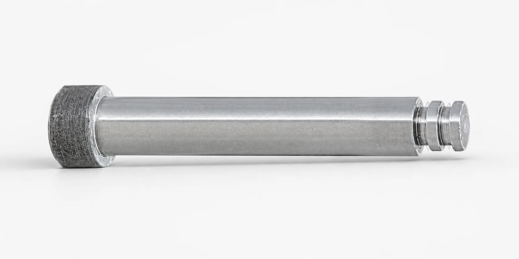
Runner Lock Pins - Straight Shaft, Super Hard Lock Tip
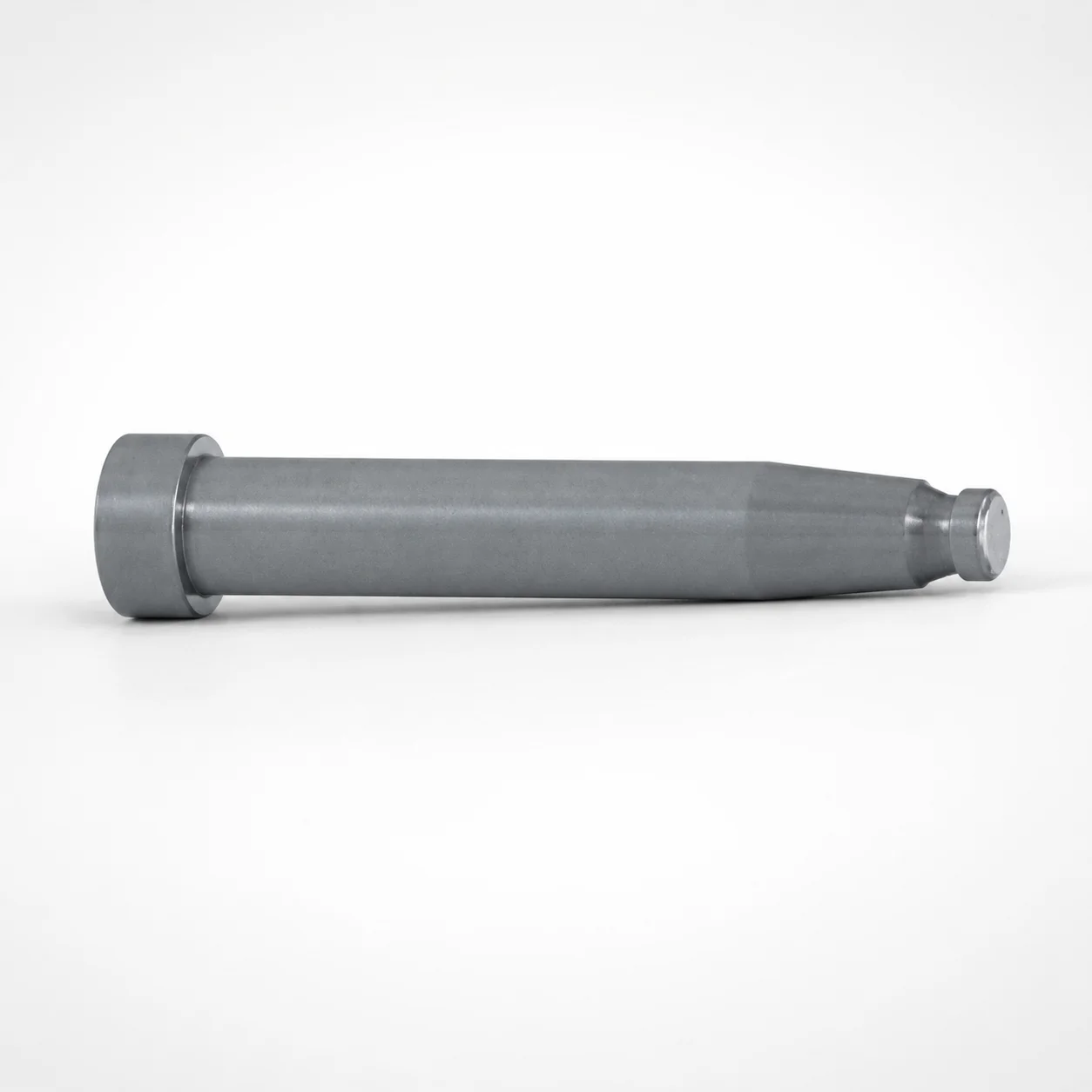
Runner lock pins - straight shaft, super hard lock tip (RLEL type) are designed to securely locate and lock runner components during mold cycles, improving assembly stability and reducing shift risk.
- Straight tip matching for consistent runner lock engagement
- Super hard lock tip for strong retention under repeated contact
- Normal pin head diameter supports stable handling and fit
- RLEL type construction suitable for runner locking applications
Specifications
6 configurations available
| Runner Lock Diameter (mm) | L (L dimension) (mm) | type |
|---|---|---|
| 2 | 10 ~ 100 | - |
| 3 | 10 ~ 100 | - |
| 4 | 10 ~ 100 | - |
| 5 | 10 ~ 100 | - |
| 6 | 15 ~ 100 | - |
| 8 | 15 ~ 100 | - |
Product Guide
Application Scenarios+
These runner lock pins are used inside injection mold tooling to prevent runner components from shifting during clamping, runner feed, and repeated cycling. In automotive connector and wire-harness connector molds, the straight-shaft geometry and straight lock tip help maintain consistent engagement with the mating runner features, improving assembly stability when vibration and tight cycle times are present.
They are also well suited for multi-cavity housings and appliance/industrial part molds where runner layout changes slightly between designs; the range of runner lock diameters (2 to 8 mm) supports matching to your cavity/core runner interface. The “super hard” lock tip is intended to provide strong retention under repeated contact, reducing the likelihood of runner misalignment that can lead to flashing or uneven gating.
- Straight tip engagement: promotes consistent lock contact for stable positioning
- Super hard tip retention: resists wear from repeated runner contact
- RLEL type design: aligned with runner locking applications in standard runner components
Material & Process Details+
The provided data identifies this as a “super hard lock tip” variant designed for strong retention under repeated runner contact. While a specific steel grade and measured hardness (HRC) are not included in the input, the engineering intent is a hardened tip region to improve wear resistance and locking durability.
- Heat treatment (functional state): hardened/super-hard tip treatment to withstand repeated mechanical engagement
- Wear resistance vs. toughness trade-off: harder tip materials increase abrasion resistance, but require careful design of the shaft and fit to avoid brittleness-related chipping
- Manufacturing process: typically produced via precision machining followed by localized hardening/heat treatment for the tip region, then final inspection for straight-shaft alignment
If you require an exact grade comparison (e.g., SKD61 vs. nitrided solutions) or verified HRC values, please share your target runner lock interface material and expected cycle count so Axiom Molds can recommend a matching hardened spec.
Sizing & Selection Guide+
Select the runner lock pin by matching the Runner Lock Diameter (mm) and the required L (L dimension) (mm) to your runner locking interface. Available diameters are 2, 3, 4, 5, 6, and 8 mm, which should align with the hole/lock seat diameter on the runner component or mating plate.
Then choose length from the supported ranges: L = 10 to 100 mm or L = 15 to 100 mm depending on the configuration. The L dimension should be long enough to ensure full lock engagement throughout normal mold deflection and parting, but not so long that it interferes with nearby surfaces during clamp/slide movement.
- Diameter matching: pick the closest diameter to the mating lock bore/feature to ensure stable engagement
- Length matching: confirm engagement depth under expected stack-up and thermal expansion
- Tolerance/fit: for locking pins, maintain clearance appropriate for alignment while preventing runner creep; verify your drawing tolerances against the pin diameter selection
Dimensions are offered as configurable variants by diameter and L range; confirm the selected configuration during quoting.
Frequently Asked Questions
Which runner lock diameter should I choose for a specific lock bore on the runner component?+
How do I determine the correct L (length) for reliable runner locking without interference?+
What does the “super hard lock tip” configuration imply for wear and lock retention?+
Why is the straight shaft / straight tip useful compared with angled or non-straight engagement features?+
Is this RLEL type suitable for standard runner locking applications in multi-cavity molds?+
Related Products
Need Custom Specifications?
Our engineering team can help with custom configurations, material selection, and volume pricing.