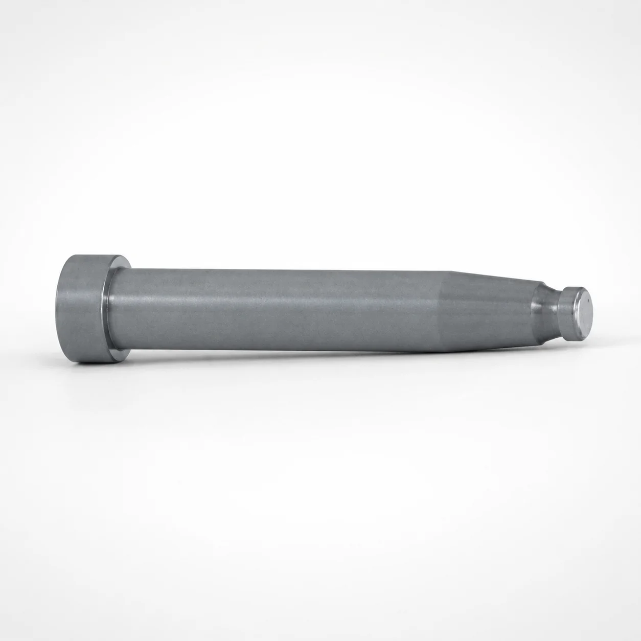
Runner Lock Pins Tapered Shaft Hard Lock Tip
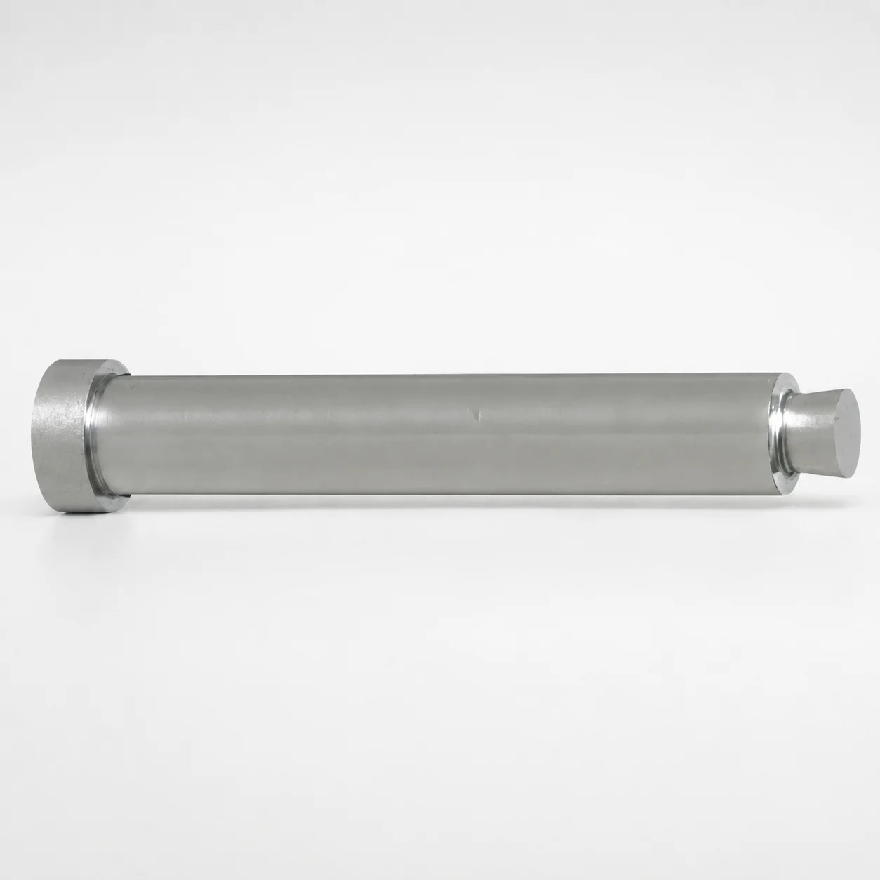
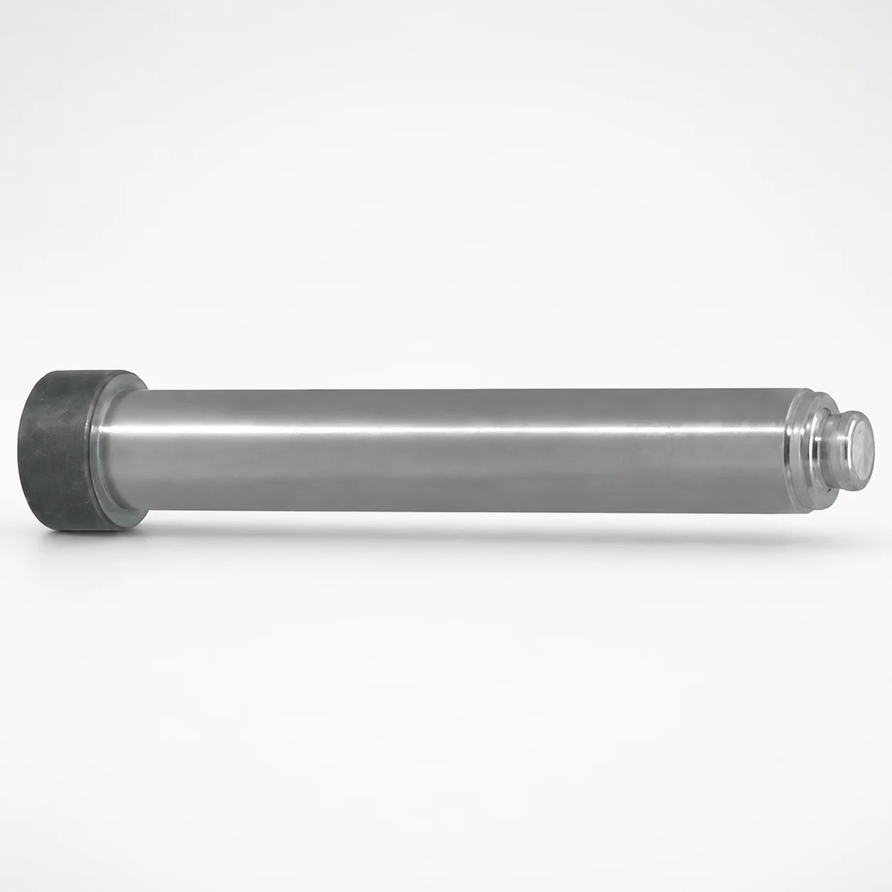
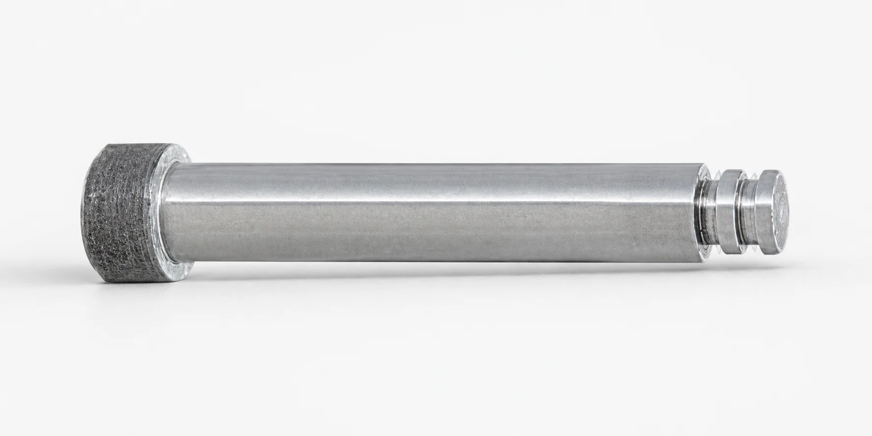
Runner Lock Pins Tapered Shaft Hard Lock Tip provide positive runner retention with a tapered matching tip profile. The hard lock geometry helps maintain stable engagement during mold operation and cyclic loads.
- Tapered shaft and hard lock tip for dependable runner locking
- Hardened locking tip design to resist wear at the contact zone
- Designed for precise lock matching to support consistent positioning
- Commonly used in runner retention and runner lock applications in tooling
Specifications
20 configurations available
| Runner Lock Diameter (mm) | Head Diameter | Dimension designation type | L (L dimension) (mm) | B (Tip length) (mm) | E (Tip width) (mm) | F (Tip diameter) (mm) | G (Taper angle) (°) | P (Tip diameter) (mm) | V (Tip diameter) (mm) | Y (Tip diameter) (mm) | type |
|---|---|---|---|---|---|---|---|---|---|---|---|
| 4 | Normal | L/P/Y/F dimension designation type | 20 ~ 100 | - | - | 1 ~ 2.9 | - | 1.1 ~ 2.4 | - | 1 ~ 2.3 | - |
| 5 | Normal | L/P/Y/F dimension designation type | 20 ~ 100 | - | - | 1.2 ~ 3.4 | - | 1.7 ~ 2.8 | - | 1.2 ~ 2.3 | - |
| 6 | Normal | L/P/Y/F dimension designation type | 25 ~ 100 | - | - | 1.5 ~ 3.9 | - | 2 ~ 3.3 | - | 1.5 ~ 2.8 | - |
| 8 | Normal | L/P/Y/F dimension designation type | 25 ~ 100 | - | - | 2 ~ 5.9 | - | 2.5 ~ 5.2 | - | 2 ~ 4.7 | - |
| 10 | Normal | L/P/Y/F dimension designation type | 25 ~ 100 | - | - | 2.5 ~ 7.9 | - | 3 ~ 7 | - | 2.5 ~ 6.5 | - |
| 4 | Normal | L/P/Y/F/B/E/V/G dimension designation type | 20 ~ 100 | 1.8 ~ 3.8 | 0.5 ~ 1.5 | 1 ~ 3.8 | 5 ~ 10 | 1.5 ~ 3.8 | 3 ~ 3.9 | 1 ~ 3.4 | - |
| 5 | Normal | L/P/Y/F/B/E/V/G dimension designation type | 20 ~ 100 | 2.3 ~ 4.5 | 0.8 ~ 2.3 | 1.2 ~ 4.8 | 5 ~ 10 | 1.7 ~ 4.8 | 3.5 ~ 4.9 | 1.2 ~ 4.4 | - |
| 6 | Normal | L/P/Y/F/B/E/V/G dimension designation type | 25 ~ 150 | 2.3 ~ 4.5 | 0.8 ~ 2.3 | 1.5 ~ 5.8 | 5 ~ 10 | 2 ~ 5.8 | 4 ~ 5.9 | 1.5 ~ 5.4 | - |
| 8 | Normal | L/P/Y/F/B/E/V/G dimension designation type | 25 ~ 150 | 3 ~ 6 | 1 ~ 3 | 2 ~ 7.8 | 5 ~ 10 | 2.5 ~ 7.8 | 6 ~ 7.9 | 2 ~ 7.4 | - |
| 10 | Normal | L/P/Y/F/B/E/V/G dimension designation type | 25 ~ 150 | 3.8 ~ 7.5 | 1.3 ~ 3.8 | 2.5 ~ 9.8 | 5 ~ 10 | 3 ~ 9.8 | 8 ~ 9.9 | 2.5 ~ 9.4 | - |
| 4 | Large | L/P/Y/F dimension designation type | 20 ~ 100 | - | - | 1 ~ 2.9 | - | 1.1 ~ 2.4 | - | 1 ~ 2.3 | - |
| 5 | Large | L/P/Y/F dimension designation type | 20 ~ 100 | - | - | 1.2 ~ 3.4 | - | 1.3 ~ 2.8 | - | 1.2 ~ 2.7 | - |
| 6 | Large | L/P/Y/F dimension designation type | 25 ~ 100 | - | - | 1.5 ~ 3.9 | - | 1.6 ~ 3.3 | - | 1.5 ~ 3.2 | - |
| 8 | Large | L/P/Y/F dimension designation type | 25 ~ 100 | - | - | 2 ~ 5.9 | - | 2.1 ~ 5.2 | - | 2 ~ 5.1 | - |
| 10 | Large | L/P/Y/F dimension designation type | 25 ~ 100 | - | - | 2.5 ~ 7.9 | - | 2.6 ~ 7 | - | 2.5 ~ 6.9 | - |
| 4 | Large | L/P/Y/F/B/E/V/G dimension designation type | 20 ~ 100 | 1.8 ~ 3.8 | 0.5 ~ 1.5 | 1 ~ 3.8 | 5 ~ 10 | 1.5 ~ 3.8 | 3 ~ 3.9 | 1 ~ 3.4 | - |
| 5 | Large | L/P/Y/F/B/E/V/G dimension designation type | 20 ~ 100 | 2.3 ~ 4.5 | 0.8 ~ 2.3 | 1.2 ~ 4.8 | 5 ~ 10 | 1.7 ~ 4.8 | 3.5 ~ 4.9 | 1.2 ~ 4.4 | - |
| 6 | Large | L/P/Y/F/B/E/V/G dimension designation type | 25 ~ 150 | 2.3 ~ 4.5 | 0.8 ~ 2.3 | 1.5 ~ 5.8 | 5 ~ 10 | 2 ~ 5.8 | 4 ~ 5.9 | 1.5 ~ 5.4 | - |
| 8 | Large | L/P/Y/F/B/E/V/G dimension designation type | 25 ~ 150 | 3 ~ 6 | 1 ~ 3 | 2 ~ 7.8 | 5 ~ 10 | 2.5 ~ 7.8 | 6 ~ 7.9 | 2 ~ 7.4 | - |
| 10 | Large | L/P/Y/F/B/E/V/G dimension designation type | 25 ~ 150 | 3.8 ~ 7.5 | 1.3 ~ 3.8 | 2.5 ~ 9.8 | 5 ~ 10 | 3 ~ 9.8 | 8 ~ 9.9 | 2.5 ~ 9.4 | - |
Product Guide
Application Scenarios+
Runner lock pins with a tapered shaft and hard lock tip are used in injection mold runner systems to keep the runner components in precise alignment under cyclic press loads. They are typically installed to locate and retain sprue/runner inserts or gate-related runner elements so that mating features repeatedly seat to the same position.
- Automotive connector and housing molds: Use the tapered lock geometry (5–10° taper) to resist micro-movement during high-cycle operation; the hardened contact zone helps maintain stable engagement at the lock tip.
- Electronics and appliance part molding: Select the appropriate runner lock diameter (4, 5, 6, 8, or 10 mm) to match cavity/core interface sizing and maintain consistent runner pitch and gate alignment.
- Medical device housings: Hardened lock-tip wear resistance supports long service life where precise repeatability is needed across many production runs.
Material & Process Details+
The available data specifies a hardened locking tip intended to resist wear at the contact zone where the tapered tip engages its mating lock feature. This design improves reliability by sustaining consistent contact geometry over repeated mold cycles.
- Heat treatment state: Hard lock tip is explicitly described as hardened; no additional bulk grade, quench & temper, or nitriding details are provided in the supplied specifications.
- Property trade-off: Hardening at the tip increases wear resistance and reduces galling during repeated engagement, while the tapered shaft geometry supports positional stability.
- Material comparison: Only the hardened-tip concept is confirmed; no alternative material grades are listed in the input, so comparative statements (e.g., SKD61 vs. SKH51) are not supported.
For hardness (HRC) and exact steel grade selection, confirm the part’s material certificate for the specific size/variant.
Sizing & Selection Guide+
Select the runner lock pin dimensions by matching the runner lock diameter and the tip geometry to the mating lock pocket/profile in the runner tooling. Choose the base diameter from 4, 5, 6, 8, or 10 mm, then pick the appropriate head size (Normal or Large) based on clearance and retention needs in your plate layout.
- Taper angle: Ensure the mating feature accepts a 5–10° taper; this directly affects seating depth and engagement consistency.
- Tip geometry matching: Use B (tip length) (1.8–3.8, 2.3–4.5, 3–6, 3.8–7.5), E (tip width) (0.5–1.5, 0.8–2.3, 1–3, 1.3–3.8), F (tip diameter) (1–2.5), and P/V/Y values within their provided ranges (e.g., V: 3–3.9 up to 8–9.9 mm; Y: 1–2.5 mm) to conform to the lock’s mating contact zone.
- Designation types: The dimension designation type can be L/P/Y/F or L/P/Y/F/B/E/V/G; ensure you reference the correct designation format when ordering the correct variant.
Specific tolerances/fit values are not provided, so dimension-critical mating should be validated with your drawing or supplier tolerance class.
Frequently Asked Questions
Which runner lock pin diameter should I select for my runner retention features (4/5/6/8/10 mm)?+
Choose the Runner Lock Diameter (mm) to match the diameter required by your mating runner lock pocket/profile. The available sizes are 4, 5, 6, 8, and 10 mm. Selecting the correct diameter is the primary driver for consistent seating and retention.
How does the 5–10° taper angle affect engagement and positioning in runner lock tooling?+
This pin family specifies a taper angle (G) range of 5–10°. The mating feature must accept the same taper so the hard lock tip seats correctly during operation, minimizing drift and maintaining alignment under cyclic loads.
What tip dimensions control the contact geometry of the hardened lock tip (B, E, F, P/V/Y)?+
Tip contact geometry is governed by B (Tip length), E (Tip width), and F (Tip diameter), plus related tip diameter parameters P and V, and Y as provided in the ranges. For example, B can be 1.8–3.8 mm and V can span 3–3.9 up to 8–9.9 mm depending on the variant. Use the values that correspond to the mating lock’s pocket dimensions.
When should I choose Head Diameter Normal vs Large for runner lock pins?+
The specification lists Head Diameter options as Normal and Large. Select Large when you need more head bearing area for retention and handling in your mold plate layout; select Normal where space is constrained.
What does the dimension designation type (L/P/Y/F vs L/P/Y/F/B/E/V/G) mean for ordering the correct variant?+
The product supports different dimension designation types: either L/P/Y/F or L/P/Y/F/B/E/V/G. Ensure you interpret the provided dimension set correctly so you select the intended combination of L (20–100 / 25–100 / 25–150 mm) and tip parameters for your mating interface. Mismatching the designation type can lead to selecting an incorrect tip geometry.
Related Products
Need Custom Specifications?
Our engineering team can help with custom configurations, material selection, and volume pricing.