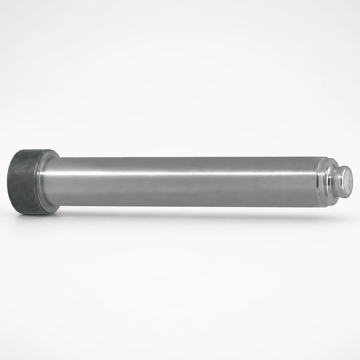
Standard Tip Runner Lock Pins - Straight Shaft
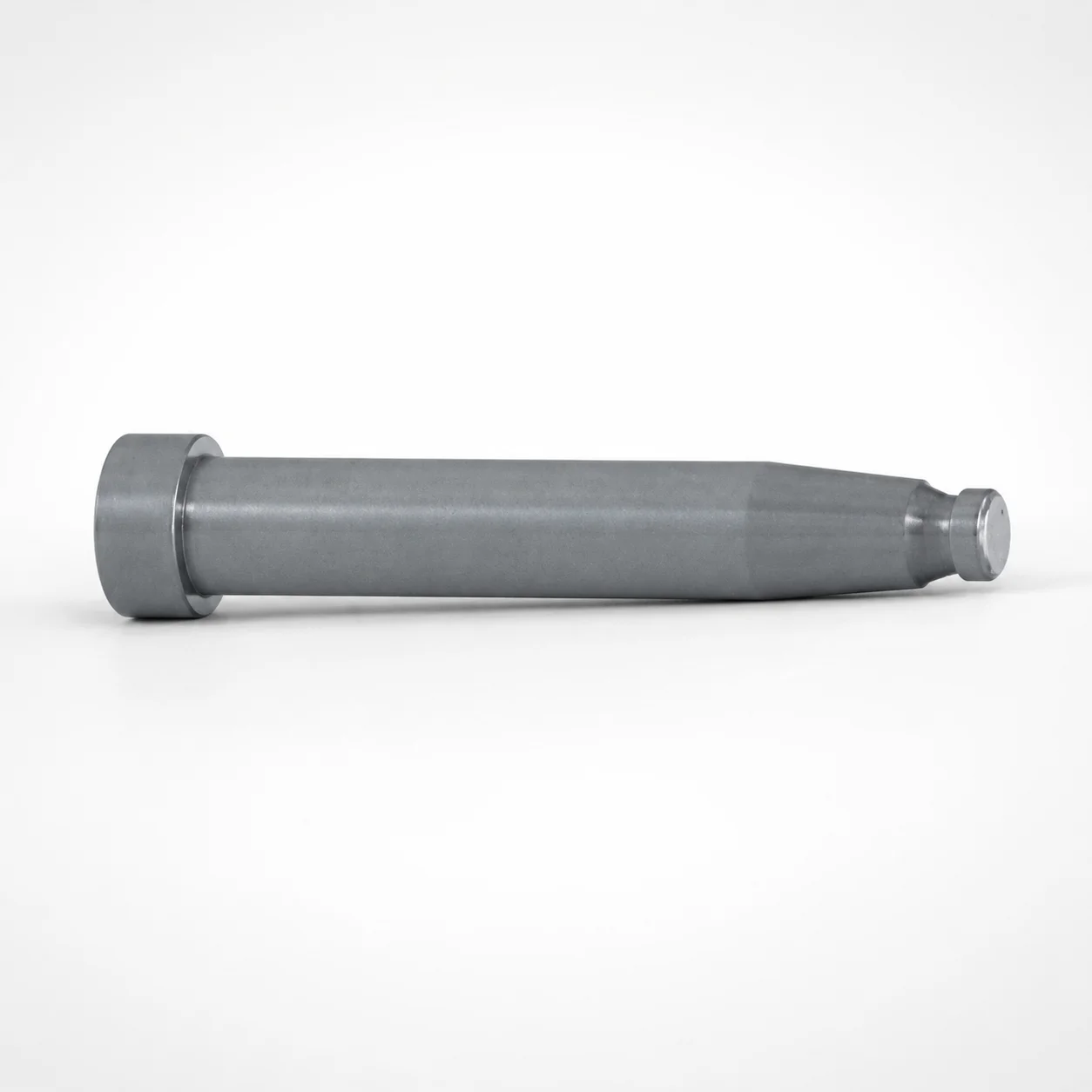
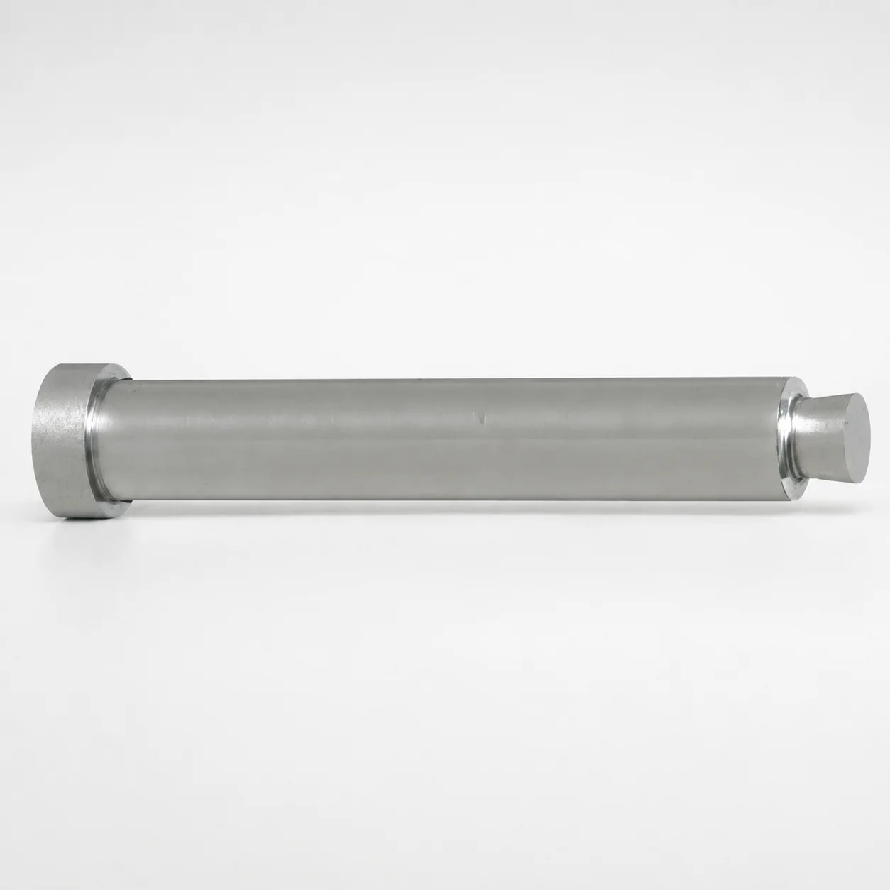
Runner lock pins (standard tip, straight shaft) are designed with a step lead and straight introduced tip to help guide accurate placement for reliable runner lock engagement. Built for stable positioning during die assembly and operation.
- Straight introduced tip with step lead improves lock alignment
- Runner lock pin construction supports consistent fit in guide systems
- Engineered to match standard runner lock workflows and assembly tooling
- Commonly used in runner lock applications requiring repeatable positioning
Specifications
10 configurations available
| Runner Lock Diameter (mm) | Dimension designation type | L (L dimension) (mm) | B (Tip length) (mm) | E (Tip width) (mm) | P (Tip diameter) (mm) | Y (Tip diameter) (mm) | type |
|---|---|---|---|---|---|---|---|
| 2 | L/P/Y dimension designation type | 10 ~ 100 | - | - | 0.9 ~ 1.8 | 0.8 ~ 1.7 | - |
| 3 | L/P/Y dimension designation type | 10 ~ 100 | - | - | 0.9 ~ 2.8 | 0.8 ~ 2.7 | - |
| 4 | L/P/Y dimension designation type | 10 ~ 100 | - | - | 1.1 ~ 3.8 | 1 ~ 3.7 | - |
| 5 | L/P/Y dimension designation type | 10 ~ 100 | - | - | 1.3 ~ 4.6 | 1.2 ~ 5.6 | - |
| 6 | L/P/Y dimension designation type | 15 ~ 100 | - | - | 1.6 ~ 5.6 | 1.5 ~ 5.5 | - |
| 2 | L/P/Y/B/E dimension designation type | 10 ~ 100 | 1.5 ~ 3 | 0.5 ~ 1 | 0.9 ~ 1.8 | 0.8 ~ 1.7 | - |
| 3 | L/P/Y/B/E dimension designation type | 10 ~ 100 | 1.5 ~ 3 | 0.5 ~ 1 | 0.9 ~ 2.8 | 0.8 ~ 2.7 | - |
| 4 | L/P/Y/B/E dimension designation type | 10 ~ 100 | 1.5 ~ 3.8 | 0.5 ~ 1 | 1.1 ~ 3.8 | 1 ~ 3.7 | - |
| 5 | L/P/Y/B/E dimension designation type | 10 ~ 100 | 1.5 ~ 4.5 | 0.5 ~ 1 | 1.3 ~ 4.6 | 1.2 ~ 4.8 | - |
| 6 | L/P/Y/B/E dimension designation type | 15 ~ 150 | 1.5 ~ 4.5 | 0.5 ~ 1 | 1.6 ~ 5.6 | 1.5 ~ 5.8 | - |
Product Guide
Application Scenarios+
Runner lock pins with a straight introduced tip are used in injection mold runner systems to ensure repeatable engagement between the runner lock components during die build and cyclic press operation.
- Automotive connector and electrical housing molds: The step lead and straight introduced tip help guide the runner lock into the correct position, supporting consistent runner alignment when assembling interchangeable runner modules.
- Hot runner and cold runner changeover tooling: Their straight shaft design improves mechanical guidance during repeated insert/remove cycles, reducing the risk of mis-locking that can cause gate eccentricity.
- Packaging and consumer part molds: For high-volume molds where the runner system must remain stable across many shots, the reliable lock alignment supports smooth presses and repeatable cavity-to-runner location.
This variant is suited because the straight introduced tip paired with the step lead is intended specifically for alignment and stable positioning in standard runner lock workflows.
Material & Process Details+
The provided specifications describe geometry (diameters and L/P/Y/B/E dimensions) rather than a steel grade, hardness, or heat treatment state. As a result, the exact material, HRC level, and any specific heat treatment (e.g., quench & temper, nitriding) cannot be stated from the given data.
When selecting runner lock pins for tooling, the key trade-off is typically wear resistance vs. toughness: higher hardness improves resistance to fretting and galling at the lock interface, while sufficient toughness helps prevent chipping under assembly loads.
- If your application experiences frequent assembly cycles or marginal lubrication, consider a hardened wear-resistant pin material with an appropriate tough core.
- If shock loads are expected during die closure, prioritize toughness and stable dimensional integrity.
For precise material properties, request the corresponding engineering datasheet for the 110200082960 series variant.
Sizing & Selection Guide+
To select the correct runner lock pin dimensions, match the runner lock diameter and the tip geometry to your mold’s guide/lock interface.
- Runner Lock Diameter (mm): choose from 2, 3, 4, 5, or 6.
- L (L dimension) (mm): select within 10–100 (or the series-specific sets 15–100 and 15–150, depending on designation type).
- Dimension designation type: confirm whether your assembly uses L/P/Y or L/P/Y/B/E, since the required parameters differ.
- P (Tip diameter) (mm): choose within the range set for your designation: 0.9–1.8, 0.9–2.8, 1.1–3.8, 1.3–4.6, or 1.6–5.6.
- Y (Tip diameter) (mm): 0.8–1.5.
- B (Tip length) (mm): 1.5–3, 1.5–3.8, or 1.5–4.5.
- E (Tip width) (mm): fixed at 0.5–1.
For fit, ensure the chosen P/Y and the runner lock diameter match the receiving bore geometry so the step lead can guide alignment without excessive clearance or binding.
Frequently Asked Questions
Which runner lock diameter sizes are available for the standard tip, straight shaft pin?+
How do I choose the correct L dimension range for the runner lock pin?+
What is the difference between the L/P/Y designation type and the L/P/Y/B/E designation type?+
How should I select P, Y, B, and E to avoid mis-locking in the runner alignment interface?+
Does this pin include information about hardness or heat treatment in the provided specifications?+
Related Products
Need Custom Specifications?
Our engineering team can help with custom configurations, material selection, and volume pricing.