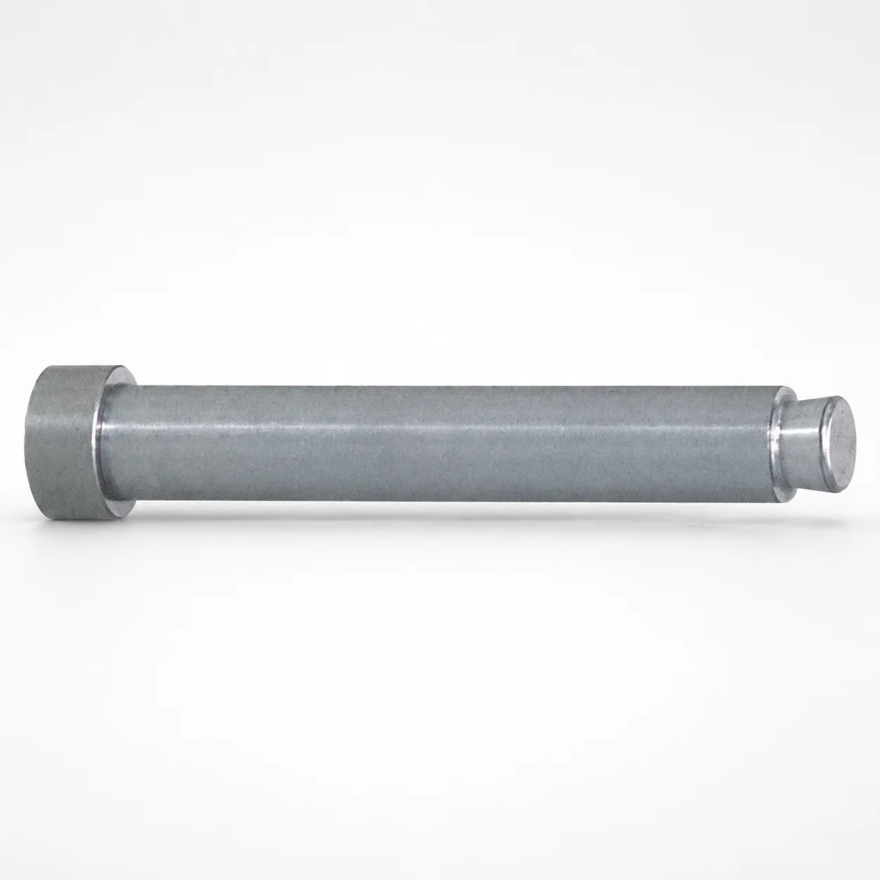
Runner Lock Pins - Straight Shaft, Standard Tip
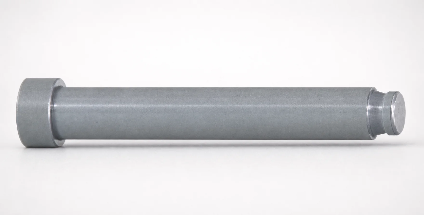
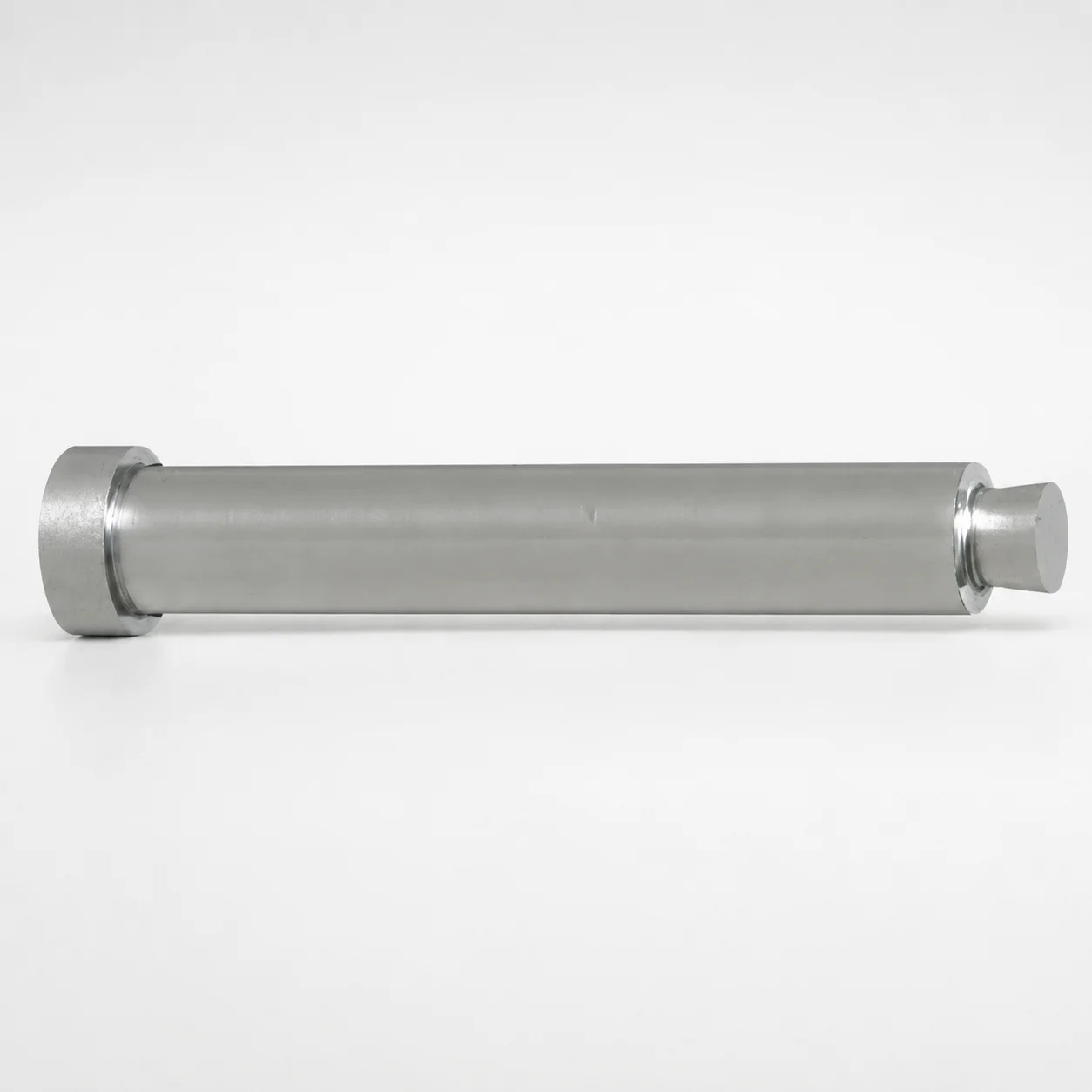
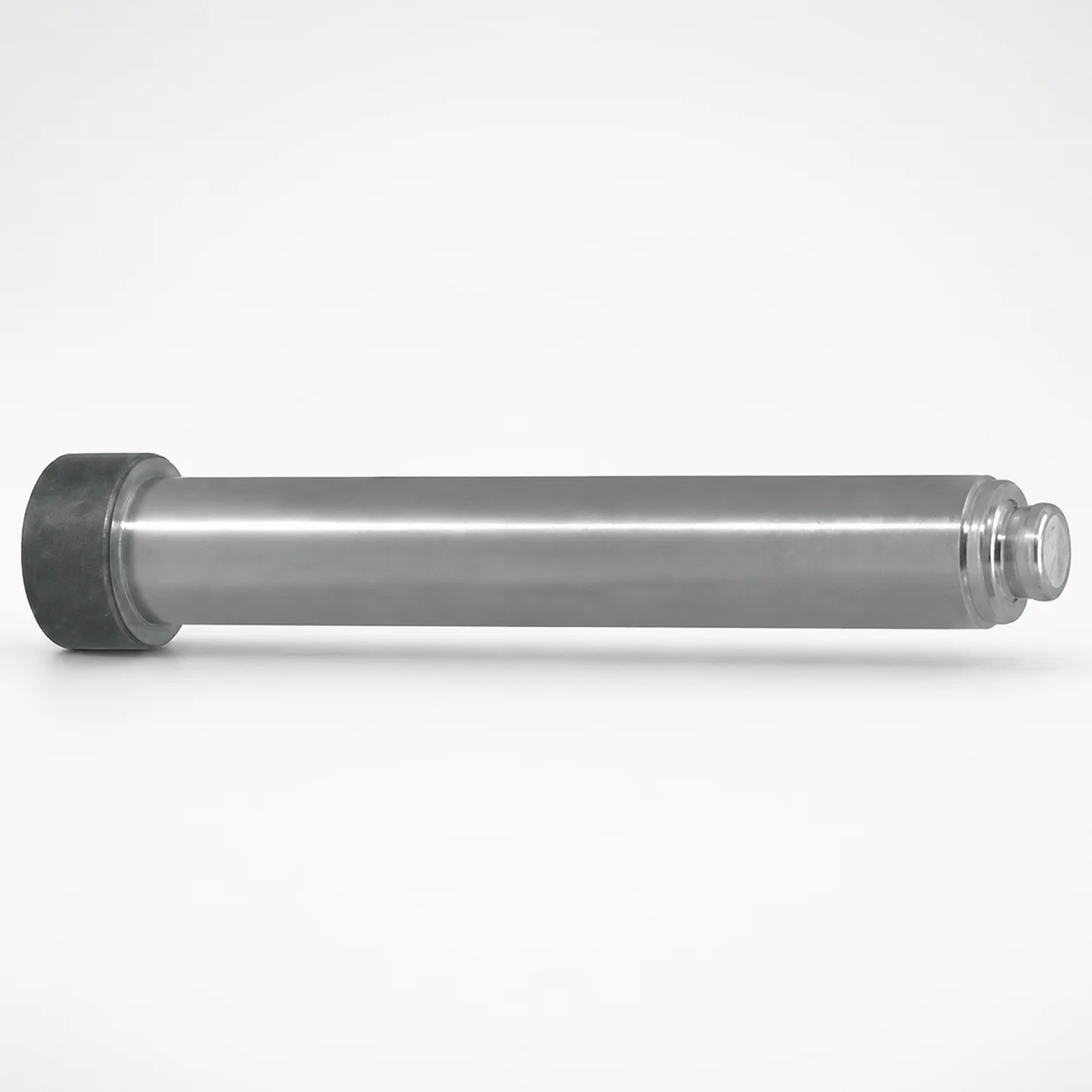
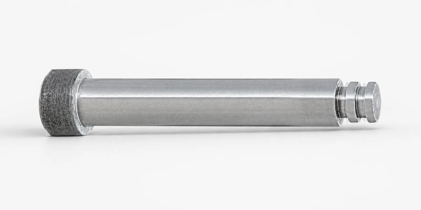
Runner lock pins - straight shaft, standard tip are designed to secure runner components using a straight locating profile. The standard tip matching shape supports reliable engagement for consistent alignment during mold assembly.
- Straight tip matching shape for dependable runner lock engagement
- Standard tip form supports stable guidance and repeatable positioning
- Designed for practical fit across a range of runner locking diameters
- Commonly used in mold runner assembly and locking operations
Specifications
89 configurations available
| Runner Lock Diameter (mm) | Head Diameter | Dimension designation type | L (L dimension) (mm) | B (Tip length) (mm) | P (Tip diameter) (mm) | Y (Tip diameter) (mm) | type |
|---|---|---|---|---|---|---|---|
| 2 | Normal | L dimension selection type | 15 | - | - | - | - |
| 2 | Normal | L dimension selection type | 20 | - | - | - | - |
| 2 | Normal | L dimension selection type | 25 | - | - | - | - |
| 2 | Normal | L dimension selection type | 30 | - | - | - | - |
| 2 | Normal | L dimension selection type | 35 | - | - | - | - |
| 2 | Normal | L dimension selection type | 40 | - | - | - | - |
| 3 | Normal | L dimension selection type | 15 | - | - | - | - |
| 3 | Normal | L dimension selection type | 20 | - | - | - | - |
| 3 | Normal | L dimension selection type | 25 | - | - | - | - |
| 3 | Normal | L dimension selection type | 30 | - | - | - | - |
| 3 | Normal | L dimension selection type | 35 | - | - | - | - |
| 3 | Normal | L dimension selection type | 40 | - | - | - | - |
| 3 | Normal | L dimension selection type | 45 | - | - | - | - |
| 3 | Normal | L dimension selection type | 50 | - | - | - | - |
| 4 | Normal | L dimension selection type | 20 | - | - | - | - |
| 4 | Normal | L dimension selection type | 25 | - | - | - | - |
| 4 | Normal | L dimension selection type | 30 | - | - | - | - |
| 4 | Normal | L dimension selection type | 35 | - | - | - | - |
| 4 | Normal | L dimension selection type | 40 | - | - | - | - |
| 4 | Normal | L dimension selection type | 45 | - | - | - | - |
| 4 | Normal | L dimension selection type | 50 | - | - | - | - |
| 4 | Normal | L dimension selection type | 60 | - | - | - | - |
| 4 | Normal | L dimension selection type | 70 | - | - | - | - |
| 4 | Normal | L dimension selection type | 80 | - | - | - | - |
| 5 | Normal | L dimension selection type | 20 | - | - | - | - |
| 5 | Normal | L dimension selection type | 25 | - | - | - | - |
| 5 | Normal | L dimension selection type | 30 | - | - | - | - |
| 5 | Normal | L dimension selection type | 35 | - | - | - | - |
| 5 | Normal | L dimension selection type | 40 | - | - | - | - |
| 5 | Normal | L dimension selection type | 45 | - | - | - | - |
| 5 | Normal | L dimension selection type | 50 | - | - | - | - |
| 5 | Normal | L dimension selection type | 60 | - | - | - | - |
| 5 | Normal | L dimension selection type | 70 | - | - | - | - |
| 5 | Normal | L dimension selection type | 80 | - | - | - | - |
| 6 | Normal | L dimension selection type | 30 | - | - | - | - |
| 6 | Normal | L dimension selection type | 35 | - | - | - | - |
| 6 | Normal | L dimension selection type | 40 | - | - | - | - |
| 6 | Normal | L dimension selection type | 45 | - | - | - | - |
| 6 | Normal | L dimension selection type | 50 | - | - | - | - |
| 6 | Normal | L dimension selection type | 60 | - | - | - | - |
| 6 | Normal | L dimension selection type | 70 | - | - | - | - |
| 6 | Normal | L dimension selection type | 80 | - | - | - | - |
| 8 | Normal | L dimension selection type | 30 | - | - | - | - |
| 8 | Normal | L dimension selection type | 35 | - | - | - | - |
| 8 | Normal | L dimension selection type | 40 | - | - | - | - |
| 8 | Normal | L dimension selection type | 45 | - | - | - | - |
| 8 | Normal | L dimension selection type | 50 | - | - | - | - |
| 8 | Normal | L dimension selection type | 60 | - | - | - | - |
| 8 | Normal | L dimension selection type | 70 | - | - | - | - |
| 8 | Normal | L dimension selection type | 80 | - | - | - | - |
Product Guide
Application Scenarios+
Runner lock pins with a straight shaft and standard tip are used inside hot/cold runner tooling to positively locate and lock runner subcomponents during assembly. The straight tip geometry improves guidance as parts are brought together, helping achieve stable seating and repeatable alignment on every cycle.
- Automotive connector and housing runner assemblies: Use for locking gate/runner elements where consistent alignment reduces mismatch at the interface and helps maintain uniform runner flow paths.
- Consumer electronics and appliance molds: Suitable when you need quick, repeatable runner component engagement; the standard tip supports dependable locking action across the available runner lock diameter range.
- General sprue-bushing and runner service tooling: Helps maintain correct positioning during maintenance or multi-cavity rebuilds by reinforcing consistent locating repeatability.
This variant is suited because it is offered for runner lock diameters 2–10 mm and supports multiple tip lengths (B) and tip diameters (P/Y), allowing designers to match the locating interface geometry to their runner locking design.
Material & Process Details+
The provided data for this MISUMI series does not specify a steel grade, heat-treatment condition, or hardness. As a result, material properties such as HRC, wear resistance, and toughness trade-offs cannot be stated from the available specifications.
For runner lock pins, the typical engineering requirement is controlled dimensional stability and adequate wear resistance at the mating surfaces. When selecting an equivalent pin material, prioritize:
- Wear resistance at the head/tip contact area for repeated assembly cycles.
- Toughness to prevent chipping of the standard tip under installation loads.
- Heat treatment that balances hardness and impact resistance (e.g., quench & temper or case hardening) consistent with mold-shop practices.
If you share the requested material/grade or a reference drawing, the material section can be aligned precisely to that standard and include the correct hardness (HRC) and heat-treatment state.
Sizing & Selection Guide+
Select the runner lock pin dimensions by matching both the runner lock diameter and the tip interface geometry to the mating runner locking feature.
- Runner lock diameter: choose based on the cavity/core lock bore or locating rail diameter within 2–10 mm.
- L (length): select the L dimension in 10–80 mm to ensure proper engagement depth without bottoming or insufficient hold-down.
- B (tip length): pick the required tip penetration using one of the available ranges: 0.8–3, 1.3–3.8, 1.5–4.5, 2–6, or 2.5–7.5 mm.
- P or Y (tip diameter): match the standard tip diameter to the mating counter-feature using P = 0.9–2.6 mm or Y = 0.8–2.5 mm.
Dimension designation is supported via L, L/P/Y, or L/P/Y/B selection types. If the interface requires a controlled fit, confirm the tolerance class from your runner lock drawing; the pin geometry is fixed by the selected designation, so fit is primarily ensured by selecting the correct diameter and engagement dimensions.
Frequently Asked Questions
How do I match the runner lock diameter when selecting this straight-shaft runner lock pin?+
What determines the required tip engagement when selecting the B (tip length) range?+
Should I select P or Y for the tip diameter, and what are the available ranges?+
How does the L dimension (length) affect runner lock performance?+
What does the dimension designation type (L / L-P-Y / L-P-Y-B) mean for configuration?+
Related Products
Need Custom Specifications?
Our engineering team can help with custom configurations, material selection, and volume pricing.