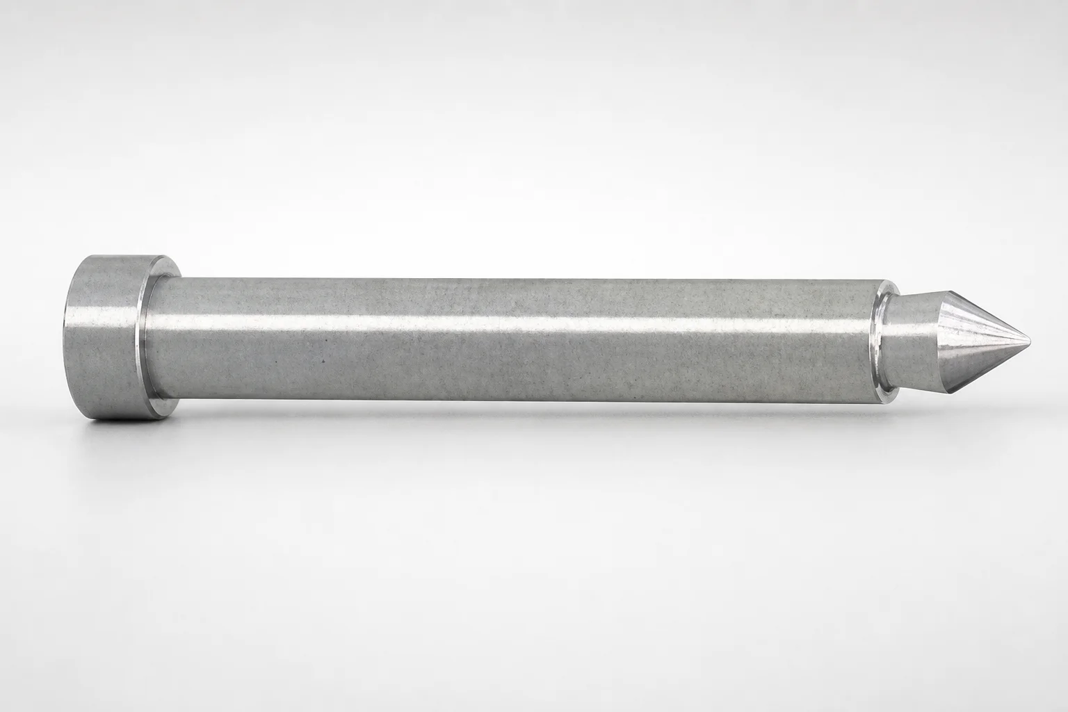
Runner Lock Pins - Straight Shaft, Cone-Shaped Tip
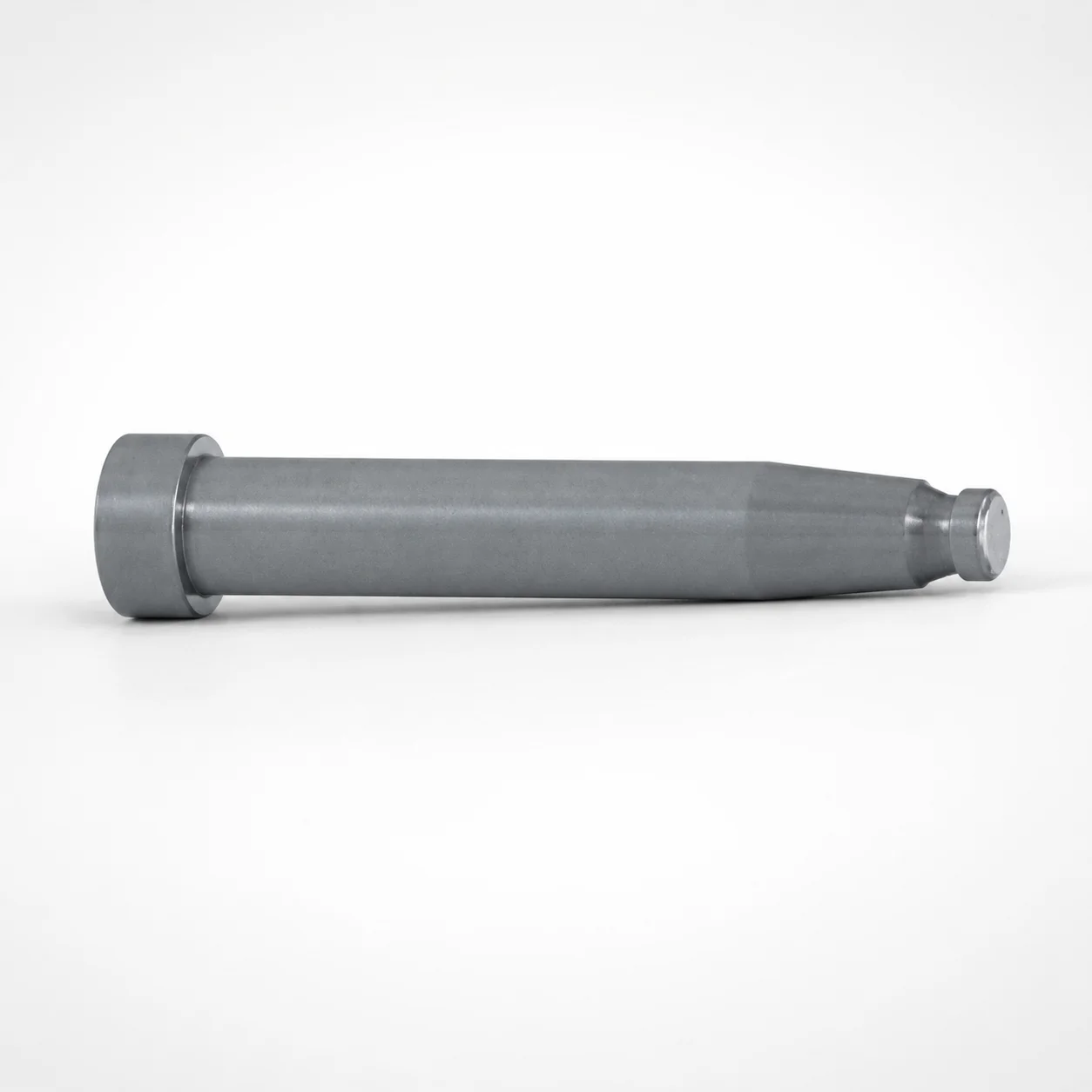
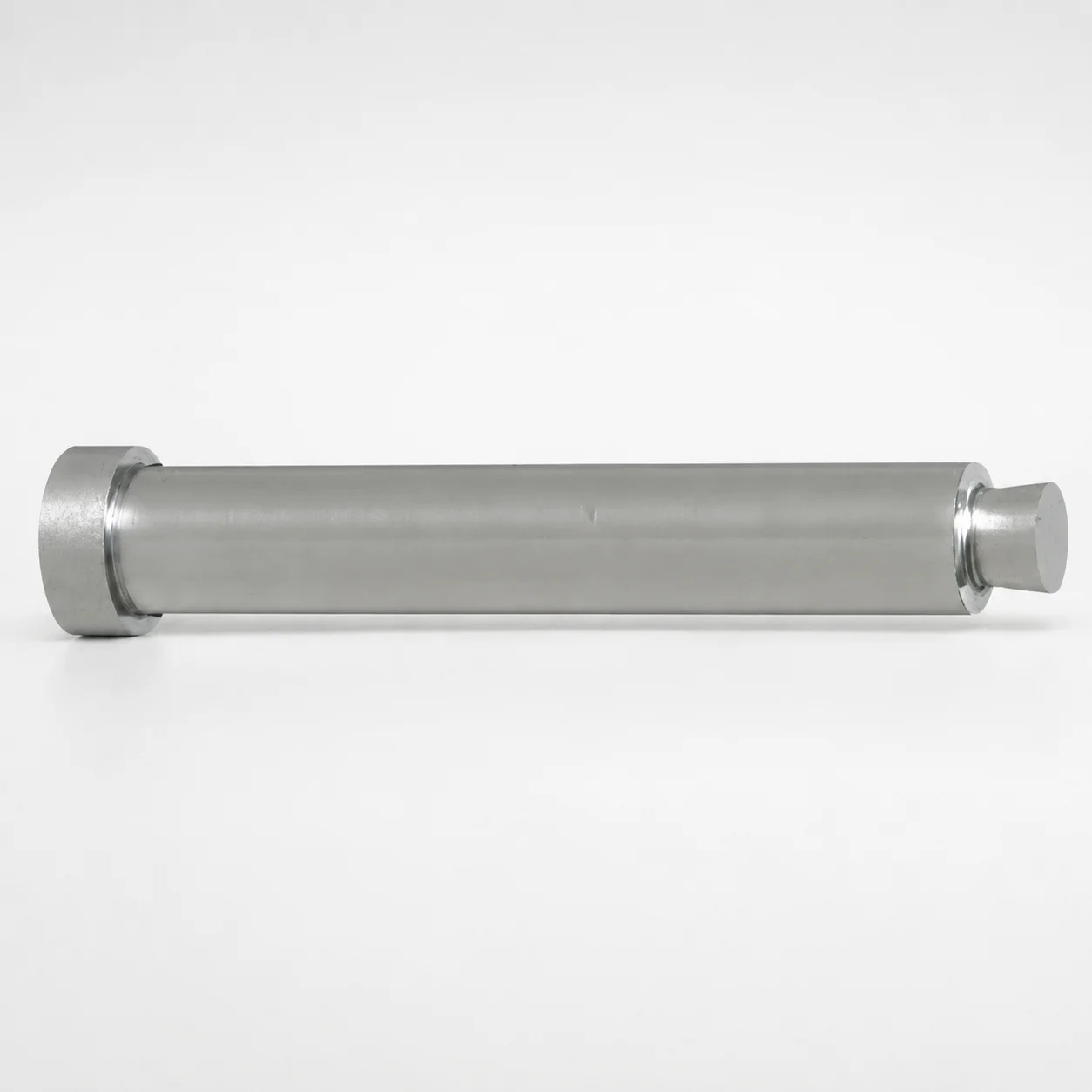
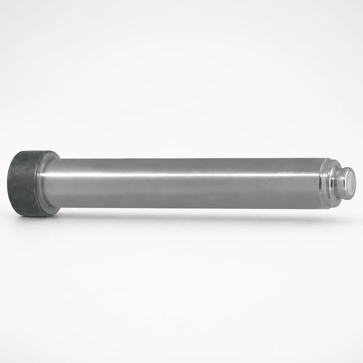
Runner lock pins - straight shaft, cone-shaped tip are designed to provide stable runner location and dependable locking in mold assemblies. The straight lead with a cone-shaped tip helps guide alignment for consistent installation and repeatable operation.
- Straight shaft with cone-shaped tip improves centering during runner engagement
- Locking-pin style supports secure placement to reduce runner shift under cycle loads
- Available head and dimension designation options help match different lock layouts
- Used in injection mold runner systems for accurate positioning during production
Specifications
40 configurations available
| Runner Lock Diameter (mm) | Head Diameter | Dimension designation type | L (L dimension) (mm) | B (Tip length) (mm) | P (Tip diameter) (mm) | S (Cone-shaped tip length) (mm) | Y (Tip diameter) (mm) | type |
|---|---|---|---|---|---|---|---|---|
| 2 | Normal | L/P/Y dimension designation type | 10 ~ 100 | - | 0.9 ~ 1.9 | - | 0.8 ~ 1.8 | - |
| 3 | Normal | L/P/Y dimension designation type | 10 ~ 100 | - | 0.9 ~ 2.9 | - | 0.8 ~ 2.8 | - |
| 4 | Normal | L/P/Y dimension designation type | 10 ~ 100 | - | 1.1 ~ 3.9 | - | 1 ~ 3.8 | - |
| 5 | Normal | L/P/Y dimension designation type | 10 ~ 100 | - | 1.3 ~ 4.9 | - | 1.2 ~ 4.8 | - |
| 6 | Normal | L/P/Y dimension designation type | 15 ~ 100 | - | 1.6 ~ 5.9 | - | 1.5 ~ 5.8 | - |
| 8 | Normal | L/P/Y dimension designation type | 20 ~ 100 | - | 2.1 ~ 7.9 | - | 2 ~ 7.8 | - |
| 10 | Normal | L/P/Y dimension designation type | 20 ~ 100 | - | 2.6 ~ 9.9 | - | 2.5 ~ 9.8 | - |
| 2 | Normal | L/P/Y/B dimension designation type | 10 ~ 100 | 1 ~ 3 | 0.9 ~ 1.9 | - | 0.8 ~ 1.8 | - |
| 3 | Normal | L/P/Y/B dimension designation type | 10 ~ 100 | 1 ~ 3 | 0.9 ~ 2.9 | - | 0.8 ~ 2.8 | - |
| 4 | Normal | L/P/Y/B dimension designation type | 10 ~ 100 | 1.3 ~ 3.8 | 1.1 ~ 3.9 | - | 1 ~ 3.8 | - |
| 5 | Normal | L/P/Y/B dimension designation type | 10 ~ 100 | 1.5 ~ 4.5 | 1.3 ~ 4.9 | - | 1.2 ~ 4.8 | - |
| 6 | Normal | L/P/Y/B dimension designation type | 20 ~ 150 | 1.5 ~ 4.5 | 1.6 ~ 5.9 | - | 1.5 ~ 5.8 | - |
| 8 | Normal | L/P/Y/B dimension designation type | 20 ~ 150 | 2 ~ 6 | 2.1 ~ 7.9 | - | 2 ~ 7.8 | - |
| 10 | Normal | L/P/Y/B dimension designation type | 20 ~ 150 | 2.5 ~ 7.5 | 2.6 ~ 9.9 | - | 2.5 ~ 9.8 | - |
| 2 | Large | L/P/Y dimension designation type | 10 ~ 100 | - | 0.9 ~ 1.9 | - | 0.8 ~ 1.8 | - |
| 3 | Large | L/P/Y dimension designation type | 10 ~ 100 | - | 0.9 ~ 2.9 | - | 0.8 ~ 2.8 | - |
| 4 | Large | L/P/Y dimension designation type | 10 ~ 100 | - | 1.1 ~ 3.9 | - | 1 ~ 3.8 | - |
| 5 | Large | L/P/Y dimension designation type | 10 ~ 100 | - | 1.3 ~ 4.9 | - | 1.2 ~ 4.8 | - |
| 6 | Large | L/P/Y dimension designation type | 20 ~ 100 | - | 1.6 ~ 5.9 | - | 1.5 ~ 5.8 | - |
| 8 | Large | L/P/Y dimension designation type | 20 ~ 100 | - | 2.1 ~ 7.9 | - | 2 ~ 7.8 | - |
| 10 | Large | L/P/Y dimension designation type | 20 ~ 100 | - | 2.6 ~ 9.9 | - | 2.5 ~ 9.8 | - |
| 2 | Large | L/P/Y/B dimension designation type | 10 ~ 100 | 1 ~ 3 | 0.9 ~ 1.9 | - | 0.8 ~ 1.8 | - |
| 3 | Large | L/P/Y/B dimension designation type | 10 ~ 100 | 1 ~ 3 | 0.9 ~ 2.9 | - | 0.8 ~ 2.8 | - |
| 4 | Large | L/P/Y/B dimension designation type | 10 ~ 100 | 1.3 ~ 3.8 | 1.1 ~ 3.9 | - | 1 ~ 3.8 | - |
| 5 | Large | L/P/Y/B dimension designation type | 10 ~ 100 | 1.5 ~ 4.5 | 1.3 ~ 4.9 | - | 1.2 ~ 4.8 | - |
| 6 | Large | L/P/Y/B dimension designation type | 20 ~ 150 | 1.5 ~ 4.5 | 1.6 ~ 5.9 | - | 1.5 ~ 5.8 | - |
| 8 | Large | L/P/Y/B dimension designation type | 20 ~ 150 | 2 ~ 6 | 2.1 ~ 7.9 | - | 2 ~ 7.8 | - |
| 10 | Large | L/P/Y/B dimension designation type | 20 ~ 150 | 2.5 ~ 7.5 | 2.6 ~ 9.9 | - | 2.5 ~ 9.8 | - |
| 2 | Normal | L dimension designation type | 10 ~ 100 | - | - | - | - | - |
| 3 | Normal | L dimension designation type | 10 ~ 100 | - | - | - | - | - |
| 4 | Normal | L dimension designation type | 10 ~ 100 | - | - | - | - | - |
| 5 | Normal | L dimension designation type | 10 ~ 100 | - | - | - | - | - |
| 6 | Normal | L dimension designation type | 15 ~ 100 | - | - | - | - | - |
| 8 | Normal | L dimension designation type | 20 ~ 100 | - | - | - | - | - |
| 2 | Normal | L/S dimension designation type | 10 ~ 100 | - | - | 1.3 ~ 3 | - | - |
| 3 | Normal | L/S dimension designation type | 10 ~ 100 | - | - | 2 ~ 5.5 | - | - |
| 4 | Normal | L/S dimension designation type | 10 ~ 100 | - | - | 2.5 ~ 7.5 | - | - |
| 5 | Normal | L/S dimension designation type | 10 ~ 100 | - | - | 3.3 ~ 9 | - | - |
| 6 | Normal | L/S dimension designation type | 15 ~ 100 | - | - | 3.3 ~ 9 | - | - |
| 8 | Normal | L/S dimension designation type | 15 ~ 100 | - | - | 5.1 ~ 8 | - | - |
Product Guide
Application Scenarios+
Runner lock pins with a straight lead and cone-shaped tip are used in injection mold runner systems to lock the runner components and maintain consistent location across production cycles. The cone-shaped tip helps self-center during assembly, reducing alignment effort and improving repeatability.
- Automotive and appliance connector molds: In multi-part molds where gate and runner sections must stay registered under vibration and high clamp-force, the secure locking-pin style helps limit runner shift and maintains stable flow path geometry.
- Packaging and household parts: For molds with frequent tool changes or periodic maintenance, the straight shaft improves guidance, while the cone tip supports reliable engagement and consistent lockup after reassembly.
- Electronics housings with tight runner-to-cavity alignment: Selecting the appropriate lock and tip dimensions supports repeatable positioning, which helps reduce knit-line variation caused by small runner misalignment.
This variant is suited because the cone-shaped tip geometry is specifically intended to guide centering and stabilize runner positioning during locking.
Material & Process Details+
The provided specifications for this runner lock-pin series do not include a steel grade or measured hardness. Therefore, material heat-treatment details (e.g., quenched & tempered, nitriding, or pre-hardened condition) and hardness trade-offs cannot be stated from the available data.
When selecting material for runner lock pins in practice, engineers typically balance wear resistance (to resist deformation under repeated engagement) against toughness (to avoid chipping or galling during assembly and cycle loads). If you need a defined recommendation, confirm the catalog material/heat-treatment option and target HRC for your mold environment (runner section steel hardness, ejection conditions, and expected cycle count).
- Note: Compare grades only after verifying the pin’s listed material option, since tolerance and wear performance depend heavily on the specific steel and heat treatment state.
Sizing & Selection Guide+
Use the runner lock diameter and tip geometry to match your mold’s runner lock bores and the mating locating features. Start by selecting the Runner Lock Diameter in the available range of 2 ~ 10 mm, then confirm the mating head style using the available Head Diameter options (Normal or Large).
- Tip diameter matching: Choose P (tip diameter) from 0.9 ~ 2.6 mm or Y (tip diameter) from 0.8 ~ 2.5 mm, ensuring clearance/fit with the runner lock socket geometry.
- Engagement length control: Set the B (tip length) from 1 ~ 3 mm, 1.3 ~ 3.8 mm, 1.5 ~ 4.5 mm, 2 ~ 6 mm, or 2.5 ~ 7.5 mm to reach sufficient locking depth without over-insertion.
- Cone length selection: Select S (cone-shaped tip length) from 1.3 ~ 3 up to 5.1 ~ 8 mm to control centering behavior and load transfer.
Dimension designation types must align with your lock layout: L/P/Y, L/P/Y/B, L only, or L/S only. For L (length) select from 10 ~ 100, 15 ~ 100, 20 ~ 100, or 20 ~ 150 mm. The exact tolerance/fit values are not provided; use your assembly drawing and bore tolerance class when determining running clearance.
Frequently Asked Questions
Which dimension should I use to specify the straight-shaft length when ordering this runner lock pin?+
How do I choose the cone-shaped tip geometry to improve runner centering during assembly?+
What tip length should I select for stable locking depth in the runner lock pocket?+
How do head diameter options affect fit with the runner lock layout?+
What runner lock diameter range is supported for this straight-shaft cone-tip pin series?+
Related Products
Need Custom Specifications?
Our engineering team can help with custom configurations, material selection, and volume pricing.