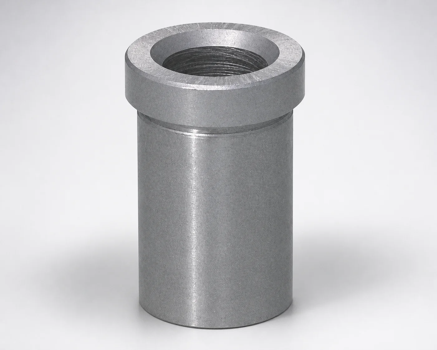
Runner Lock Pin Bushings - Reversed Taper Lead
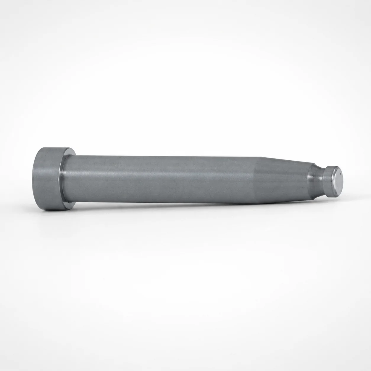
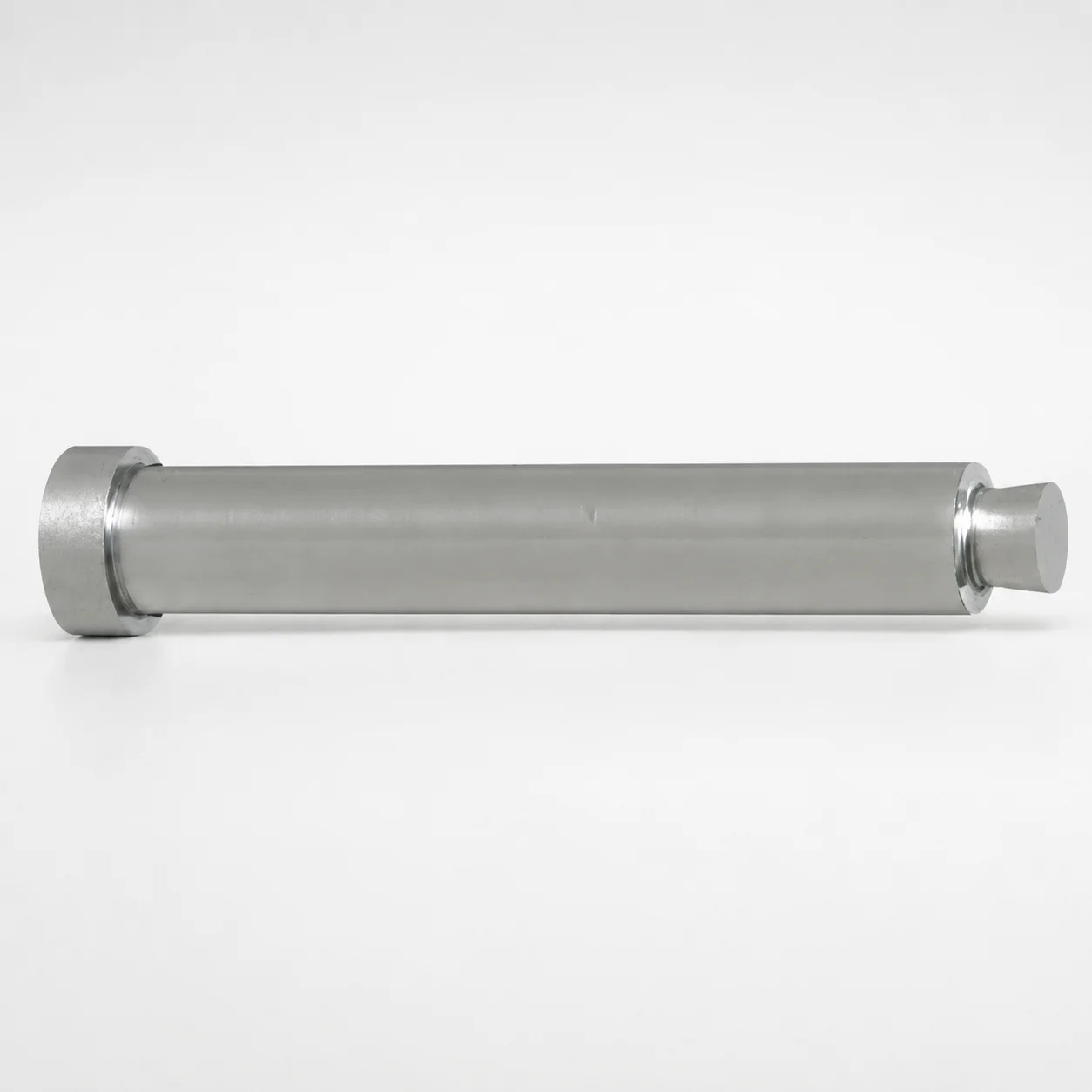
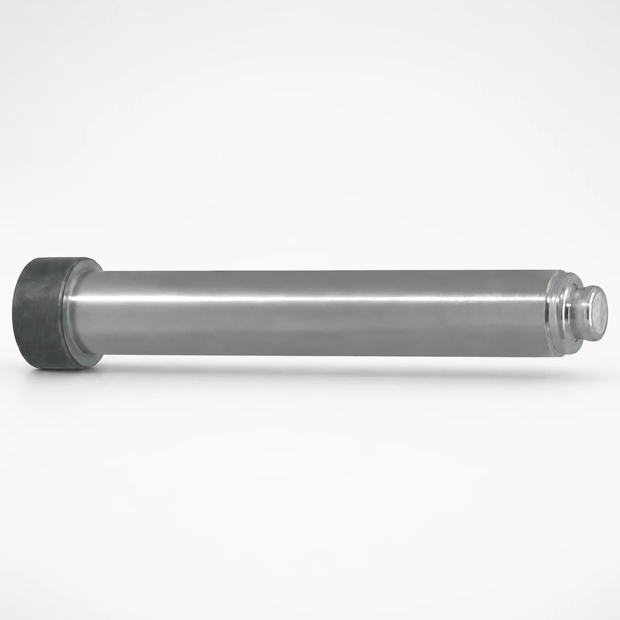
Runner lock pin bushings - reversed taper lead provide consistent alignment support for runner lock pin systems, helping maintain a secure lock during press operation. The reversed taper lead guides engagement for repeatable positioning under production load.
- Reversed taper lead design improves centering during lock-pin insertion
- Dimensional accuracy supports stable runner lock fit and repeatable assembly
- Designed to work across common bushing tip options for runner lock pins
- Suitable for tool runner systems requiring dependable pin retention
Specifications
25 configurations available
| Bushing Tip Shape | Applicable runner lock pin diameter (mm) | L (L dimension) (mm) | A (Tip diameter) (mm) | LC (L dimension alteration) (mm) | V (Tip diameter) (mm) | type |
|---|---|---|---|---|---|---|
| For straight | 3 | 10 ~ 15 | - | - | - | - |
| For straight | 3 | - | - | 10.1 ~ 15 | - | - |
| For straight | 4 | 10 ~ 25 | - | - | - | - |
| For straight | 4 | - | - | 10.1 ~ 25 | - | - |
| For straight | 5 | 10 ~ 25 | - | - | - | - |
| For straight | 5 | - | - | 10 ~ 25 | - | - |
| For straight | 6 | 15 ~ 30 | - | - | - | - |
| For straight | 6 | - | - | 15 ~ 30 | - | - |
| For straight | 8 | 25 | - | - | - | - |
| For straight | 8 | - | - | 20 ~ 25 | - | - |
| For straight, tapered | 2 | 15 ~ 25 | 2.5 ~ 3.5 | - | 2.5 ~ 4 | - |
| For straight, tapered | 2 | - | 2.5 ~ 3.5 | 15.1 ~ 24.9 | 2.5 ~ 4 | - |
| For straight, tapered | 3 | 10 ~ 25 | 3.5 ~ 4.5 | - | 3.5 ~ 5 | - |
| For straight, tapered | 3 | - | 3.5 ~ 4.5 | 10.1 ~ 24.9 | 3.5 ~ 5 | - |
| For straight, tapered | 4 | 15 ~ 25 | 4.5 ~ 6.5 | - | 4.5 ~ 7 | - |
| For straight, tapered | 4 | - | 4.5 ~ 6.5 | 15.1 ~ 24.9 | 4.5 ~ 7 | - |
| For straight, tapered | 5 | 15 ~ 25 | 5.5 ~ 6.5 | - | 5.5 ~ 7 | - |
| For straight, tapered | 5 | - | 5.5 ~ 6.5 | 15.1 ~ 24.9 | 5.5 ~ 7 | - |
| For straight, tapered | 6 | 15 ~ 30 | 6.5 ~ 8.5 | - | 6.5 ~ 9 | - |
| For straight, tapered | 6 | - | 6.5 ~ 8.5 | 15.1 ~ 29.9 | 6.5 ~ 9 | - |
| For straight, tapered | 8 | 15 ~ 30 | 8.5 ~ 11.5 | - | 8.5 ~ 12 | - |
| For straight, tapered | 8 | - | 8.5 ~ 11.5 | 15.1 ~ 29.9 | 8.5 ~ 12 | - |
| For tapered | 4 | 10 ~ 25 | - | - | - | - |
| For tapered | 5 | 10 ~ 25 | - | - | - | - |
| For tapered | 6 | 15 ~ 25 | - | - | - | - |
Product Guide
Application Scenarios+
These runner lock pin bushings are used inside injection mold runner lock systems to guide pin insertion and preserve alignment during repeated press cycles. The reversed taper lead creates a controlled centering effect as the lock pin engages, which helps reduce misalignment risk when tooling is closed under load.
- Runner lock assemblies for hot/cold runner interchange: Use the bushing to maintain stable lock geometry across operational temperature swings by promoting repeatable engagement of the runner lock pin.
- Automotive and appliance component molds: In high-throughput tools where shutdown/startup cycles are frequent, the dimensional accuracy supports consistent pin retention and prevents partial lock-up.
- Multi-cavity molds with runner module repeatability requirements: The tapered lead improves centering for reliable positioning, helping keep runner layout stable from cycle to cycle.
This variant is suited because the reversed taper lead is specifically intended to stabilize alignment during lock-pin insertion, matching the common runner lock pin diameter options and bushing tip configurations listed in the specs.
Material & Process Details+
The provided product metadata does not specify a steel grade, heat treatment state, or hardness (HRC). Because runner lock bushings must maintain geometric stability and wear resistance under repeated pin engagement, Axiom Molds typically supplies such components with hardened tool steels; however, the exact grade and treatment for series code 110200084020 cannot be confirmed from the input data.
For engineering verification, request the material certificate for the exact grade and heat treatment (e.g., quench & temper, nitrided, or through-hardened condition), and confirm hardness level in HRC. This is important because higher hardness generally improves wear resistance of the lead/tip area, while reduced toughness can increase chipping risk under misalignment or shock loads.
- Hardness target: Confirm HRC spec from documentation before final design.
- Wear vs. toughness: Tune material selection based on pin material and expected insertion/withdrawal loads.
Sizing & Selection Guide+
Selection starts by matching the applicable runner lock pin diameter to the bushing configuration. This series supports runner lock pin diameters of 2, 3, 4, 5, 6, and 8 mm, so choose the bushing whose specified diameter range corresponds to your lock pin.
- Tip geometry: Select the Bushing Tip Shape (straight or tapered) and the matching Tip diameter (A) range: 2.5–3.5, 3.5–4.5, 4.5–6.5, 5.5–6.5, 6.5–8.5, or 8.5–11.5 (as applicable to your model).
- Length (L): Choose L from 10–15, 10–25, 15–30, 25, or 15–25 mm to achieve required engagement depth.
- Lead/tip variation: Use LC (10–20 mm) and V (tip diameter options: 2.5–4, 3.5–5, 4.5–7, 5.5–7, 6.5–9, 8.5–12) only when your pin system design specifies those dimensions.
Check fit strategy (clearance/interference) in your runner lock pin system; even with correct nominal sizing, tolerances can affect centering and retention performance. Dimensions listed above are configuration-dependent rather than fully fixed across all variants.
Frequently Asked Questions
Which bushing variant should I select for a runner lock pin with diameter 5 mm?+
How does the reversed taper lead affect centering during runner lock-pin insertion?+
What dimensions do I use to ensure correct engagement depth and runner lock stability?+
Can this runner lock pin bushing be used with both straight and tapered pin tip designs?+
Do you have material hardness and heat treatment data for series 110200084020?+
Related Products
Need Custom Specifications?
Our engineering team can help with custom configurations, material selection, and volume pricing.