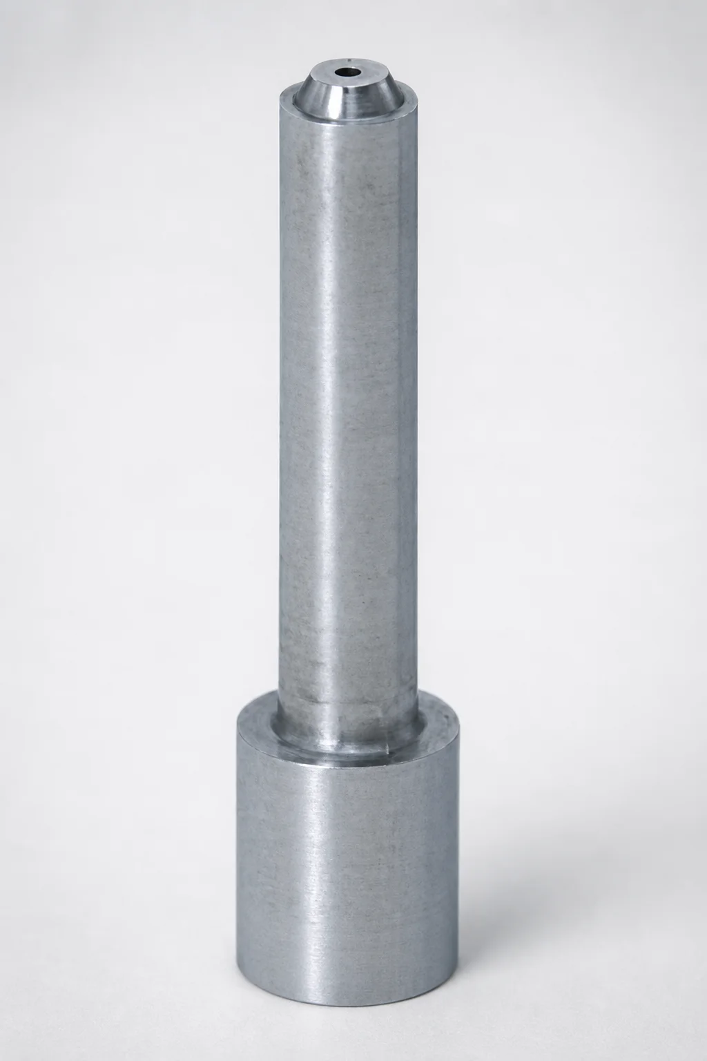
SKH51 Steel Round Gate Transition Pin-Point Gate Bushings (SR)
Pin-Point Gate Bushings (SR) (SKH51 steel) with a round gate transition are designed to create consistent gate size and smooth flow during molding. The SR tip step shape supports reliable pin-point gate formation for repeatable production.
- Round gate transition promotes stable melt flow into the pin-point gate
- Made from SKH51 steel with quenched hardening for wear resistance
- Controlled tip geometry with P dimension tolerance ±0.01 for dependable fit
- Used in injection molds to improve gate control for precision parts
Specifications
50 configurations available
| Tip Type | Tip Shape | P Dimension Tolerance | Tip Straight Tolerance | D (Outer diameter) (mm) | No. (Nominal diameter) (mm) | A (Taper angle) (°) | B (Length excluding the lengths of head and tip) (mm) | C (Tip length) (mm) | K (Cutting angle) (°) | L (L dimension) (mm) | P (Tip diameter) (mm) | R (Tip R) (mm) | S (Tip angle) (°) | V (Tip diameter) (mm) | type |
|---|---|---|---|---|---|---|---|---|---|---|---|---|---|---|---|
| Normal | 1A | ±0.01 | 0 to 0.2 | 2.51 ~ 3 | 2.5 | 1 ~ 3 | 4 ~ 6 | 0.2 ~ 0.5 | 20 ~ 30 | 8 ~ 25 | 0.3 ~ 0.6 | - | - | 1.5 ~ 2.4 | - |
| Normal | 1A | ±0.01 | 0 to 0.2 | - | 2.5 | 1 ~ 3 | 4 ~ 6 | 0.2 ~ 0.5 | 20 ~ 30 | 8 ~ 25 | 0.3 ~ 0.6 | - | - | 1.5 ~ 2.4 | - |
| Normal | 1A | ±0.01 | 0 to 0.2 | 3.01 ~ 4 | 3 | 1 ~ 3 | 5 ~ 9 | 0.3 ~ 0.8 | 20 ~ 30 | 10 ~ 40 | 0.5 ~ 0.9 | - | - | 2 ~ 2.9 | - |
| Normal | 1A | ±0.01 | 0 to 0.2 | 4.01 ~ 5 | 4 | 1 ~ 3 | 5 ~ 30 | 0.3 ~ 0.8 | 20 ~ 30 | 10 ~ 40 | 0.6 ~ 1.2 | - | - | 2.5 ~ 3.9 | - |
| Normal | 1A | ±0.01 | 0 to 0.2 | 5.01 ~ 7 | 5 | 1 ~ 3 | 5 ~ 35 | 0.5 ~ 1.5 | 20 ~ 30 | 15 ~ 60 | 0.8 ~ 1.5 | - | - | 3.5 ~ 4.9 | - |
| Normal | 1A | ±0.01 | 0 to 0.2 | 6.01 ~ 8 | 6 | 1 ~ 3 | 5 ~ 50 | 0.5 ~ 1.5 | 20 ~ 30 | 15 ~ 60 | 1 ~ 1.6 | - | - | 4 ~ 4.9 | - |
| Normal | 1A | ±0.01 | 0 to 0.2 | 8.01 ~ 10 | 8 | 1 ~ 3 | 5 ~ 50 | 0.5 ~ 1.5 | 20 ~ 30 | 15 ~ 60 | 1.2 ~ 1.6 | - | - | 4.5 ~ 7.9 | - |
| Normal | 2A | ±0.01 | 0 to 0.2 | 2.51 ~ 3 | 2.5 | 1 ~ 3 | 4 ~ 6 | - | 20 ~ 30 | 8 ~ 25 | 0.3 ~ 0.6 | - | - | - | - |
| Normal | 2A | ±0.01 | 0 to 0.2 | 3.01 ~ 4 | 3 | 1 ~ 3 | 5 ~ 9 | - | 20 ~ 30 | 10 ~ 40 | 0.5 ~ 0.9 | - | - | - | - |
| Normal | 2A | ±0.01 | 0 to 0.2 | 4.01 ~ 5 | 4 | 1 ~ 3 | 5 ~ 30 | - | 20 ~ 30 | 10 ~ 60 | 0.6 ~ 1.2 | - | - | - | - |
| Normal | 2A | ±0.01 | 0 to 0.2 | 5.01 ~ 7 | 5 | 1 ~ 3 | 5 ~ 35 | - | 20 ~ 30 | 15 ~ 60 | 0.8 ~ 1.5 | - | - | - | - |
| Normal | 2A | ±0.01 | 0 to 0.2 | 6.01 ~ 8 | 6 | 1 ~ 3 | 5 ~ 50 | - | 20 ~ 30 | 15 ~ 60 | 1 ~ 1.6 | - | - | - | - |
| Normal | 2A | ±0.01 | 0 to 0.2 | 8.01 ~ 10 | 8 | 1 ~ 3 | 5 ~ 50 | - | 20 ~ 30 | 15 ~ 60 | 1.2 ~ 1.6 | - | - | - | - |
| Normal | 3A | ±0.01 | 0 to 0.2 | 2.51 ~ 3 | 2.5 | 1 ~ 3 | 4 ~ 6 | 0.2 ~ 0.5 | 20 ~ 30 | 8 ~ 40 | 0.3 ~ 0.6 | - | 1 ~ 45 | - | - |
| Normal | 3A | ±0.01 | 0 to 0.2 | 3.01 ~ 4 | 3 | 1 ~ 3 | 5 ~ 9 | 0.3 ~ 0.8 | 20 ~ 30 | 10 ~ 40 | 0.5 ~ 0.9 | - | 1 ~ 45 | - | - |
| Normal | 3A | ±0.01 | 0 to 0.2 | 4.01 ~ 5 | 4 | 1 ~ 3 | 5 ~ 30 | 0.3 ~ 0.8 | 20 ~ 30 | 10 ~ 40 | 0.6 ~ 1.2 | - | 1 ~ 45 | - | - |
| Normal | 3A | ±0.01 | 0 to 0.2 | 5.01 ~ 7 | 5 | 1 ~ 3 | 5 ~ 35 | 0.5 ~ 1.5 | 20 ~ 30 | 15 ~ 60 | 0.8 ~ 1.5 | - | 1 ~ 45 | - | - |
| Normal | 3A | ±0.01 | 0 to 0.2 | 6.01 ~ 8 | 6 | 1 ~ 3 | 5 ~ 50 | 0.5 ~ 1.5 | 20 ~ 30 | 15 ~ 60 | 1 ~ 1.6 | - | 1 ~ 50 | - | - |
| Normal | 3A | ±0.01 | 0 to 0.2 | 8.01 ~ 10 | 8 | 1 ~ 3 | 5 ~ 50 | 0.5 ~ 1.5 | 20 ~ 30 | 15 ~ 60 | 1.2 ~ 1.6 | - | 1 ~ 60 | - | - |
| Normal | 4A | ±0.01 | 0 to 0.2 | 2.51 ~ 3 | 2.5 | 1 ~ 3 | 4 ~ 6 | 0.2 ~ 0.5 | 20 ~ 30 | 8 ~ 25 | 0.3 ~ 0.6 | 0.6 ~ 1 | - | - | - |
| Normal | 4A | ±0.01 | 0 to 0.2 | 3.01 ~ 4 | 3 | 1 ~ 3 | 5 ~ 9 | 0.3 ~ 0.8 | 20 ~ 30 | 10 ~ 40 | 0.5 ~ 0.9 | 0.8 ~ 1.5 | - | - | - |
| Normal | 4A | ±0.01 | 0 to 0.2 | 4.01 ~ 5 | 4 | 1 ~ 3 | 5 ~ 30 | 0.3 ~ 0.8 | 20 ~ 30 | 10 ~ 40 | 0.6 ~ 1.2 | 0.8 ~ 1.5 | - | - | - |
| Normal | 4A | ±0.01 | 0 to 0.2 | 5.01 ~ 7 | 5 | 1 ~ 3 | 5 ~ 35 | 0.5 ~ 1.5 | 20 ~ 30 | 15 ~ 60 | 0.8 ~ 1.5 | 1 ~ 2 | - | - | - |
| Normal | 4A | ±0.01 | 0 to 0.2 | 6.01 ~ 8 | 6 | 1 ~ 3 | 5 ~ 50 | 0.5 ~ 1.5 | 20 ~ 30 | 15 ~ 60 | 1 ~ 1.6 | 1.5 ~ 3 | - | - | - |
| Normal | 4A | ±0.01 | 0 to 0.2 | 8.01 ~ 10 | 8 | 1 ~ 3 | 5 ~ 50 | 0.5 ~ 1.5 | 20 ~ 30 | 15 ~ 60 | 1.2 ~ 1.6 | 2 ~ 4 | - | - | - |
| Normal | 5A | ±0.01 | 0 to 0.2 | 2.51 ~ 3 | 2.5 | 1 ~ 3 | 4 ~ 6 | 0.2 ~ 0.5 | 20 ~ 30 | 8 ~ 25 | 0.3 ~ 0.6 | - | - | - | - |
| Normal | 5A | ±0.01 | 0 to 0.2 | 3.01 ~ 4 | 3 | 1 ~ 3 | 5 ~ 9 | 0.3 ~ 0.8 | 20 ~ 30 | 10 ~ 40 | 0.5 ~ 0.9 | - | - | - | - |
| Normal | 5A | ±0.01 | 0 to 0.2 | 4.01 ~ 5 | 4 | 1 ~ 3 | 5 ~ 30 | 0.3 ~ 0.8 | 20 ~ 30 | 10 ~ 40 | 0.6 ~ 1.2 | - | - | - | - |
| Normal | 5A | ±0.01 | 0 to 0.2 | 5.01 ~ 7 | 5 | 1 ~ 3 | 5 ~ 35 | 0.5 ~ 1.5 | 20 ~ 30 | 15 ~ 60 | 0.8 ~ 1.5 | - | - | - | - |
| Normal | 5A | ±0.01 | 0 to 0.2 | 6.01 ~ 8 | 6 | 1 ~ 3 | 5 ~ 50 | 0.5 ~ 1.5 | 20 ~ 30 | 15 ~ 60 | 1 ~ 1.6 | - | - | - | - |
| Normal | 5A | ±0.01 | 0 to 0.2 | 8.01 ~ 10 | 8 | 1 ~ 3 | 5 ~ 50 | 0.5 ~ 1.5 | 20 ~ 30 | 15 ~ 60 | 1.2 ~ 1.6 | - | - | - | - |
| Acute angle | 1A | - | 0 to 0.05 | 2.51 ~ 3 | 2.5 | 1 ~ 3 | 4 ~ 6 | 0.2 ~ 0.5 | 20 ~ 30 | 8 ~ 25 | 0.3 ~ 0.6 | - | - | 1.5 ~ 2.4 | - |
| Acute angle | 1A | - | 0 to 0.05 | - | 2.5 | 1 ~ 3 | 4 ~ 6 | 0.2 ~ 0.5 | 20 ~ 30 | 8 ~ 25 | 0.3 ~ 0.6 | - | - | 1.5 ~ 2.4 | - |
| Acute angle | 1A | - | 0 to 0.05 | 3.01 ~ 4 | 3 | 1 ~ 3 | 5 ~ 9 | 0.3 ~ 0.8 | 20 ~ 30 | 10 ~ 40 | 0.5 ~ 0.9 | - | - | 2 ~ 2.9 | - |
| Acute angle | 1A | - | 0 to 0.05 | 4.01 ~ 5 | 4 | 1 ~ 3 | 5 ~ 30 | 0.3 ~ 0.8 | 20 ~ 30 | 10 ~ 40 | 0.6 ~ 1.2 | - | - | 2.5 ~ 3.9 | - |
| Acute angle | 1A | - | 0 to 0.05 | 5.01 ~ 7 | 5 | 1 ~ 3 | 5 ~ 35 | 0.5 ~ 1.5 | 20 ~ 30 | 15 ~ 60 | 0.8 ~ 1.5 | - | - | 3.5 ~ 4.9 | - |
| Acute angle | 1A | - | 0 to 0.05 | 6.01 ~ 8 | 6 | 1 ~ 3 | 5 ~ 50 | 0.5 ~ 1.5 | 20 ~ 30 | 15 ~ 60 | 1 ~ 1.6 | - | - | 4 ~ 4.9 | - |
| Acute angle | 1A | - | 0 to 0.05 | 8.01 ~ 10 | 8 | 1 ~ 3 | 5 ~ 50 | 0.5 ~ 1.5 | 20 ~ 30 | 15 ~ 60 | 1.2 ~ 1.6 | - | - | 4.5 ~ 7.9 | - |
| Acute angle | 2A | - | 0 to 0.05 | 2.51 ~ 3 | 2.5 | 1 ~ 3 | 4 ~ 6 | - | 20 ~ 30 | 8 ~ 25 | 0.3 ~ 0.6 | - | - | - | - |
| Acute angle | 2A | - | 0 to 0.05 | 3.01 ~ 4 | 3 | 1 ~ 3 | 5 ~ 9 | - | 20 ~ 30 | 10 ~ 40 | 0.5 ~ 0.9 | - | - | - | - |
| Acute angle | 2A | - | 0 to 0.05 | 4.01 ~ 5 | 4 | 1 ~ 3 | 5 ~ 30 | - | 20 ~ 30 | 10 ~ 60 | 0.6 ~ 1.2 | - | - | - | - |
| Acute angle | 2A | - | 0 to 0.05 | 5.01 ~ 7 | 5 | 1 ~ 3 | 5 ~ 35 | - | 20 ~ 30 | 15 ~ 60 | 0.8 ~ 1.5 | - | - | - | - |
| Acute angle | 2A | - | 0 to 0.05 | 6.01 ~ 8 | 6 | 1 ~ 3 | 5 ~ 50 | - | 20 ~ 30 | 15 ~ 60 | 1 ~ 1.6 | - | - | - | - |
| Acute angle | 2A | - | 0 to 0.05 | 8.01 ~ 10 | 8 | 1 ~ 3 | 5 ~ 50 | - | 20 ~ 30 | 15 ~ 60 | 1.2 ~ 1.6 | - | - | - | - |
| Acute angle | 3A | - | 0 to 0.05 | 2.51 ~ 3 | 2.5 | 1 ~ 3 | 4 ~ 6 | 0.2 ~ 0.5 | 20 ~ 30 | 8 ~ 40 | 0.3 ~ 0.6 | - | 1 ~ 45 | - | - |
| Acute angle | 3A | - | 0 to 0.05 | 3.01 ~ 4 | 3 | 1 ~ 3 | 5 ~ 9 | 0.3 ~ 0.8 | 20 ~ 30 | 10 ~ 40 | 0.5 ~ 0.9 | - | 1 ~ 45 | - | - |
| Acute angle | 3A | - | 0 to 0.05 | 4.01 ~ 5 | 4 | 1 ~ 3 | 5 ~ 30 | 0.3 ~ 0.8 | 20 ~ 30 | 10 ~ 40 | 0.6 ~ 1.2 | - | 1 ~ 45 | - | - |
| Acute angle | 3A | - | 0 to 0.05 | 5.01 ~ 7 | 5 | 1 ~ 3 | 5 ~ 35 | 0.5 ~ 1.5 | 20 ~ 30 | 15 ~ 60 | 0.8 ~ 1.5 | - | 1 ~ 45 | - | - |
| Acute angle | 3A | - | 0 to 0.05 | 6.01 ~ 8 | 6 | 1 ~ 3 | 5 ~ 50 | 0.5 ~ 1.5 | 20 ~ 30 | 15 ~ 60 | 1 ~ 1.6 | - | 1 ~ 50 | - | - |
| Acute angle | 3A | - | 0 to 0.05 | 8.01 ~ 10 | 8 | 1 ~ 3 | 5 ~ 50 | 0.5 ~ 1.5 | 20 ~ 30 | 15 ~ 60 | 1.2 ~ 1.6 | - | 1 ~ 60 | - | - |
Product Guide
Application Scenarios+
Pin-point gate bushings like this round-transition SR type are used in injection mold tooling where repeatable micro-gate geometry is critical. The round gate transition helps smooth the melt pathway from the sprue/bushing area into the pin-point gate, reducing flow interruptions and supporting consistent gate size from cycle to cycle.
- Automotive connector housings: suited for high-volume parts that require stable pin-point gate formation to minimize gate vestige variation and maintain dimensional consistency.
- Consumer electronics enclosures: controlled tip geometry supports dependable gate forming when molding thin-walled features and when tighter control of gate freeze-off is needed.
- Medical device housings: helps achieve uniform gating behavior for precise filling, supporting repeatability where process stability is a priority.
With SKH51 steel and a controlled tip geometry variant, this bushing is appropriate when both wear resistance at the gate region and stable forming of the pin-point gate tip are required.
Material & Process Details+
This SR bushing is made from SKH51 steel. SKH51 is an AISI M2 equivalent high-speed steel known for strong abrasion resistance at elevated temperatures experienced near the gate during repeated molding cycles.
- Heat treatment state: the product description indicates quenched hardening for wear resistance, supporting longer service life at the contact and eroding zones.
- Hardness & performance: quenched/hardened high-speed steels typically deliver high hardness and improved wear resistance, though ultimate toughness can be lower than more ductile tool steels.
- Geometry + material trade-off: the controlled tip geometry paired with hardened SKH51 helps maintain gate definition; however, the higher hardness means designs should avoid excessive mechanical shock and ensure proper alignment.
Compared with lower-alloy, pre-hardened steels, SKH51’s wear resistance is typically superior for gate-region erosion, while toughness is managed via appropriate hardening and geometry stability.
Sizing & Selection Guide+
Select the bushing by matching the nominal diameter (No.) and the outer diameter D to the mold’s gate bushing bore and the sprue/gating layout. Available D (mm) ranges are 2.51–3, 3.01–4, 4.01–5, 5.01–7, 6.01–8, and 8.01–10, and the corresponding Nominal diameter No. (mm) options include 2.5, 3, 4, 5, 6, and 8.
- Verify the P (tip diameter) (mm) you need for the pin-point gate: options include 0.3–0.6, 0.5–0.9, 0.6–1.2, 0.8–1.5, 1–1.6, and 1.2–1.6.
- Choose the tip length C (mm) from 0.2–0.5, 0.3–0.8, or 0.5–1.5 to set the effective gate contact length.
- Match overall positioning using B (length excluding head/tip) and L (L dimension) ranges (e.g., B: 4–6 up to 5–50; L: 8–25 up to 15–60).
Maintain the specified P dimension tolerance of ±0.01 when designing gate repeatability; tip straight tolerance is variable (0–0.2 or 0–0.05), so ensure your cavity/core finish and alignment support the intended fit.
Frequently Asked Questions
Which tip diameter (P) range should I select to achieve a specific pin-point gate diameter?+
How do I choose the correct outer diameter (D) and nominal diameter (No.) for the mold bushing bore?+
What tip length (C) and internal length (B/L) should be used to control gate contact and gate freeze behavior?+
Which tip type (Normal vs. Acute angle) is better for stable pin-point gate formation?+
What does the fixed taper angle (A) and cutting angle (K) imply for tooling compatibility?+
Related Products
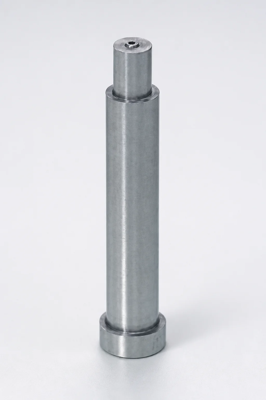
SKH51 Steel Pin-Point Gate Bushings with Head - Round Gate Transition (SR)
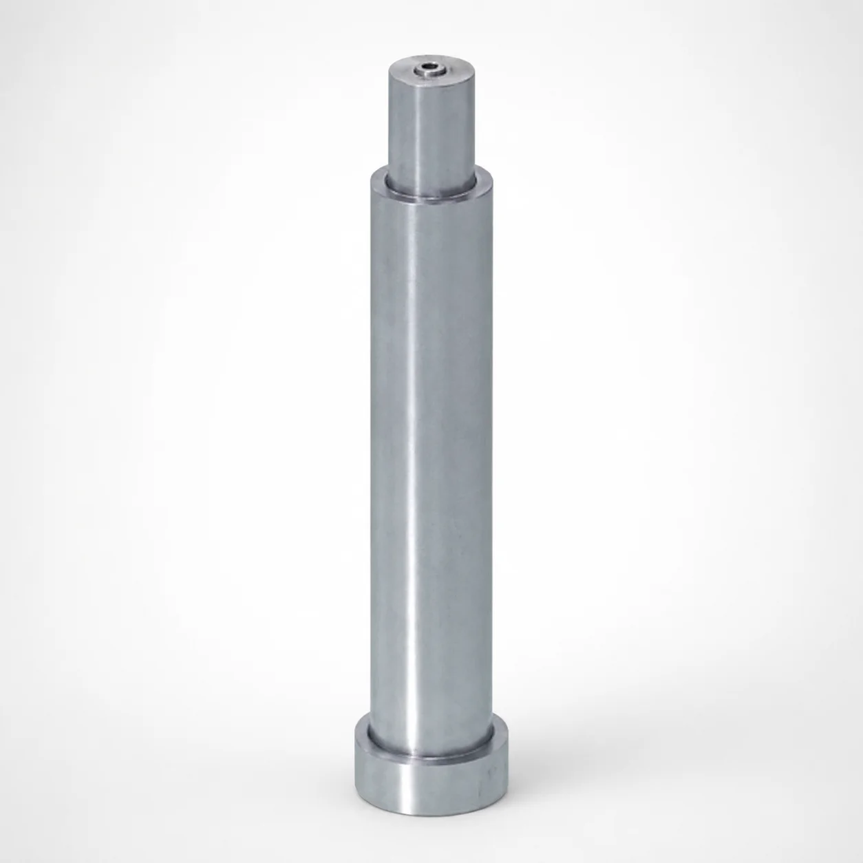
SKH51 Steel Pin-Point Gate Bushings with Head
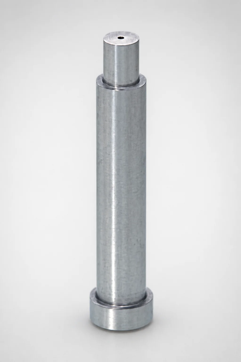
JIS Standard SKH51 Steel Pin-Point Gate Bushings (PGHTBL) with Head
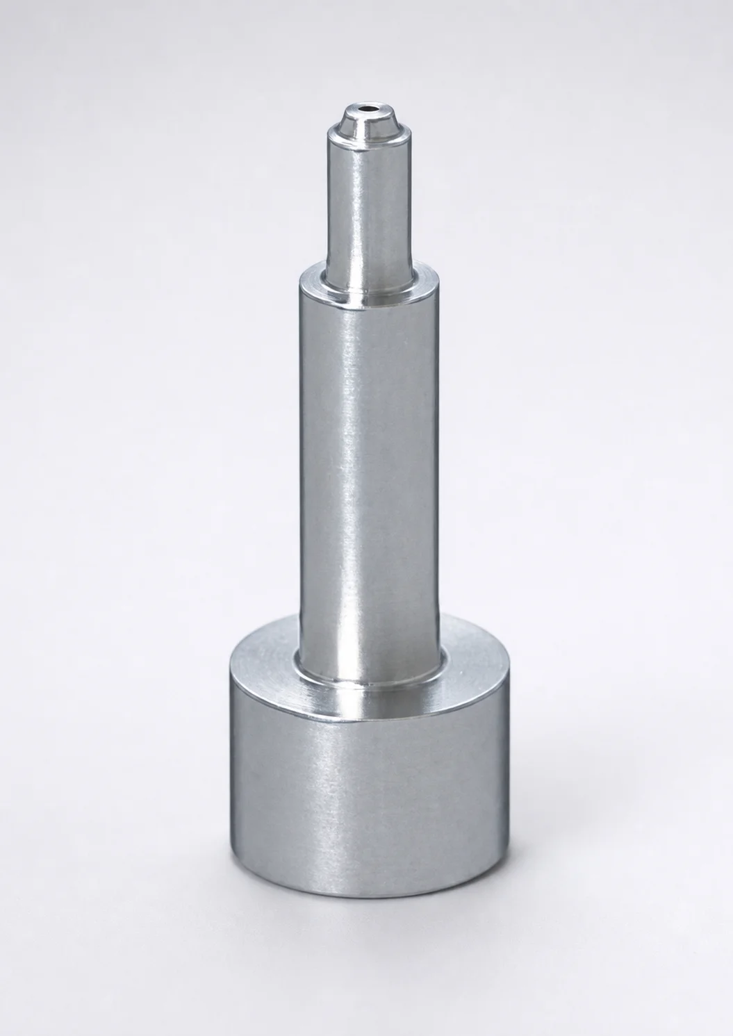
SKH51 Steel Pin-Point Gate Bushings with Head - Round Gate Transition
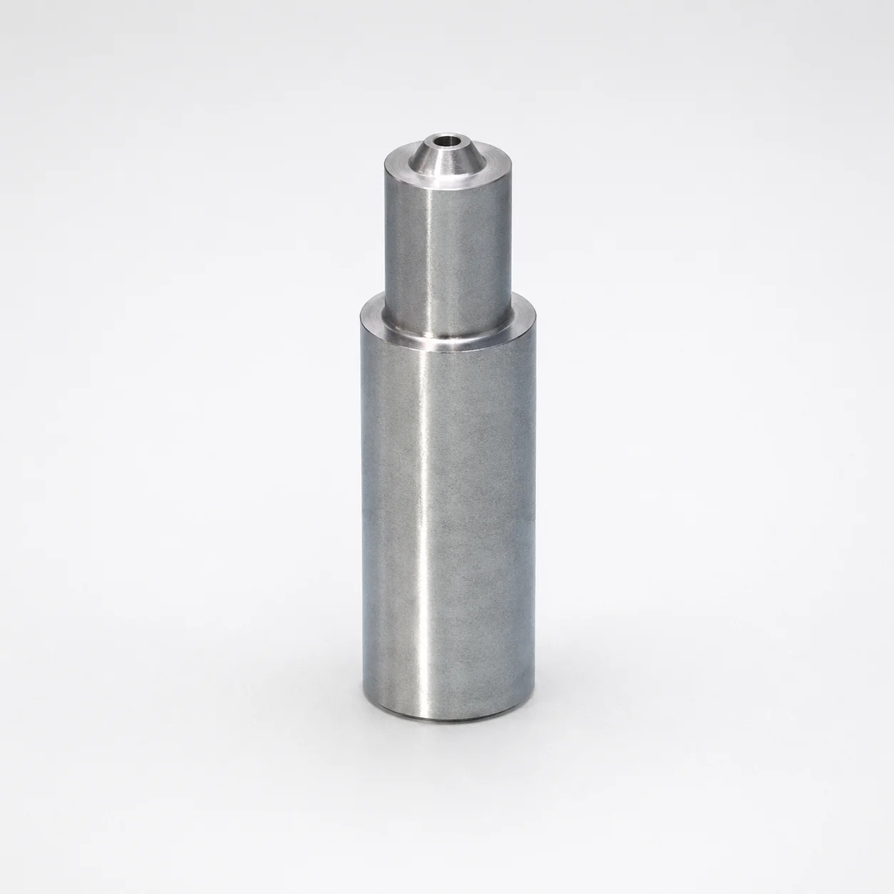
SKH51 Steel Pin-Point Gate Bushings Round Gate Transition SR
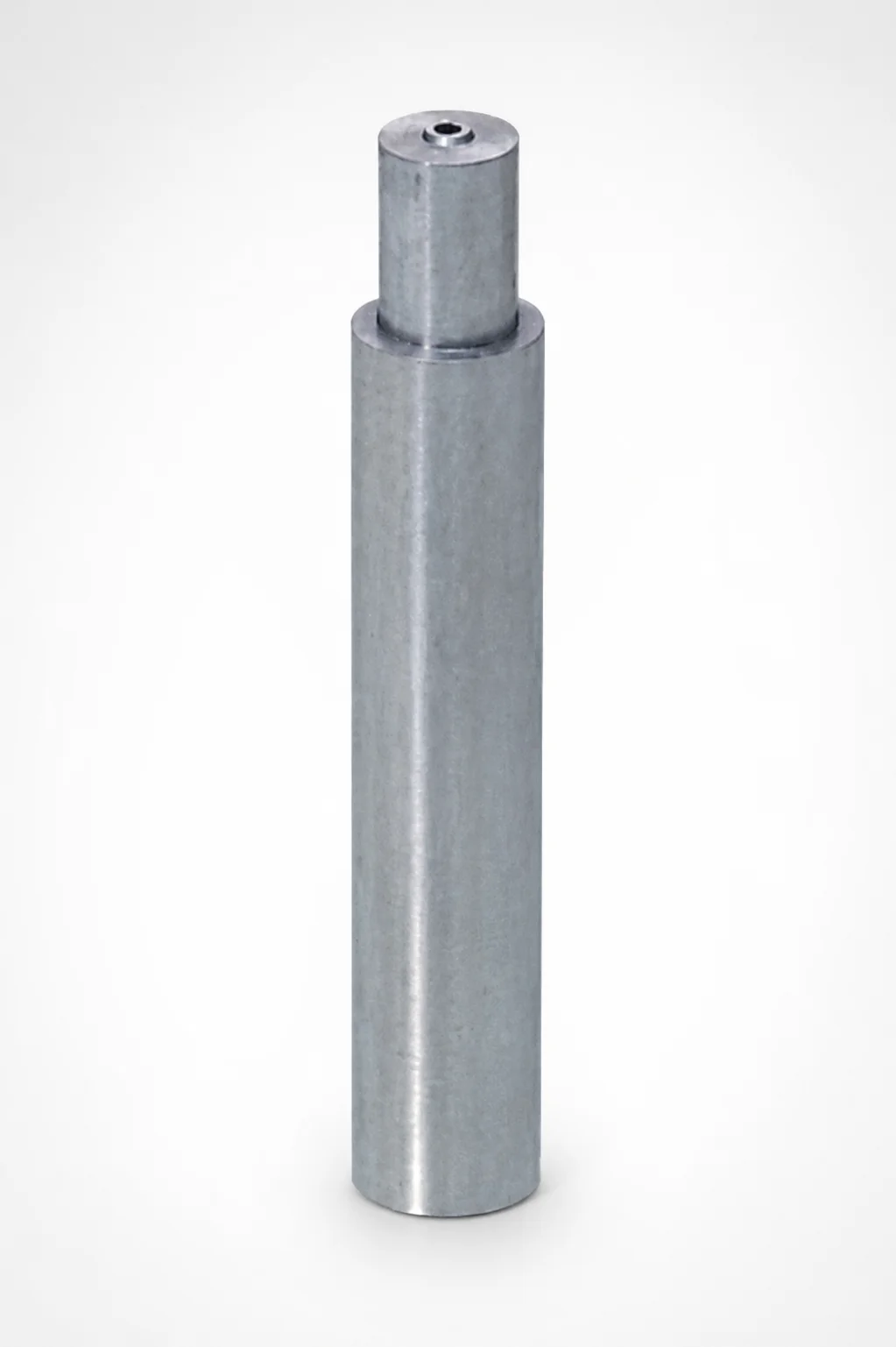
JIS Standard SKH51 Steel Pin-Point Gate Bushings Round Gate Transition SR
Need Custom Specifications?
Our engineering team can help with custom configurations, material selection, and volume pricing.