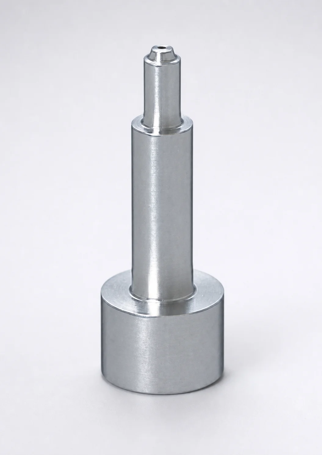
SKH51 Steel Pin-Point Gate Bushings with Head - Round Gate Transition
Pin-Point Gate Bushings with Head (SKH51 steel) are designed with a round gate transition to support smooth flow from the runner into the mold cavity while maintaining precise positioning. The head design improves handling and assembly stability for repeatable gate geometry.
- Round gate transition supports controlled flow for reliable gate formation
- SKH51 steel construction with quenched hardening steel properties for wear resistance
- Honed machining supports tight D dimension tolerance (0/-0.005) for consistent fit
- Commonly used in pin-point gating applications where accurate gate alignment is critical
Specifications
6 configurations available
| P Dimension Tolerance | D (Outer diameter) (mm) | A (Secondary sprue angle) (°) | C (Tip length) (mm) | L (L dimension) (mm) | P (Tip diameter) (mm) | type |
|---|---|---|---|---|---|---|
| ±0.01 | 1.5 | 2 | 0 ~ 0.5 | 10 ~ 20 | 0.3 | - |
| ±0.01 | 1.6 | 2 | 0 ~ 0.5 | 10 ~ 20 | 0.3 ~ 0.4 | - |
| ±0.01 | 1.8 | 2 | 0 ~ 0.5 | 10 ~ 20 | 0.3 ~ 0.5 | - |
| ±0.005 | 1.5 | 2 | 0 ~ 0.5 | 10 ~ 20 | 0.3 | - |
| ±0.005 | 1.6 | 2 | 0 ~ 0.5 | 10 ~ 20 | 0.3 ~ 0.4 | - |
| ±0.005 | 1.8 | 2 | 0 ~ 0.5 | 10 ~ 20 | 0.3 ~ 0.5 | - |
Product Guide
Application Scenarios+
This pin-point gate bushing with head is used in injection molds to control the transition from the runner system into the cavity with a round gate transition. The design supports stable gate formation by smoothing polymer flow and helping maintain repeatable gate geometry.
- Automotive connector and small housing molds: Ideal for applications that require tight alignment of the gate tip to the cavity location. The honed outer diameter and head improve assembly stability during shutoff and maintenance.
- Electronics and precision component housings: Used when consistent gate vestige and minimized flow disruption are needed. The round transition supports controlled transfer into the cavity while the SKH51 tool steel helps maintain performance under frequent cycles.
- Pin-point gated packaging or thin-wall parts: Suitable where a compact sprue/gate interface reduces material flow path length. The short tip length range helps match small gate sizes without overextending into the part.
Material & Process Details+
SKH51 is a high-speed steel grade typically selected for tooling requiring excellent wear resistance at the gate interface. Compared to more general purpose mold steels, SKH51 offers better sliding/abrasion performance, which helps preserve tip geometry over long production runs.
- Heat treatment: Quenched hardening for a hardened, wear-focused microstructure (described as quenched hardening properties in this variant’s spec).
- Hardness & trade-offs: Hardened SKH51 generally targets high HRC levels for wear resistance, with slightly reduced toughness relative to tougher steels. This makes it important to control contact loads and ensure proper alignment in the bushing seat.
- Machining: Honed machining is used to support tight D dimension tolerance (0/-0.005), improving fit consistency and reducing gate alignment drift.
Sizing & Selection Guide+
Selection starts by matching the outer diameter (D) to your bushing bore. Available D sizes are 1.5, 1.6, and 1.8 mm, and the honed D is specified with tight tolerance 0/-0.005, so confirm your seat/ream dimensions to achieve the intended press-fit or sliding fit.
- Gate interface geometry: Choose the P (tip diameter) option that matches your desired pin-point gate size: 0.3, 0.3–0.4, or 0.3–0.5 mm. Keep compatibility with your cavity gate land and sprue thickness targets.
- Tip length: Use C (tip length) = 0 to 0.5 mm to prevent excessive penetration into the cavity while achieving stable gate formation.
- Length and sprue relationship: Set L = 10 to 20 mm to align the bushing head and tip location within the tool stack. The secondary sprue angle is fixed at A = 2°, so cavity/runner layout must accommodate this.
- Tolerance matching: For variable P and Tolerance ranges, finalize the cavity/gate drawings using the selected P range to avoid mismatch at shutoff.
Frequently Asked Questions
How does the round gate transition in this pin-point gate bushing affect gate formation and alignment?+
The round gate transition is intended to smooth the polymer flow from the runner into the cavity, improving control of gate formation. Combined with the bushing head for stable assembly, it helps maintain repeatable gate geometry during operation.
What D (outer diameter) tolerance should be considered when fitting the bushing into the mold bore?+
The bushing’s D outer diameter is available at 1.5, 1.6, or 1.8 mm with a tight tolerance of 0/-0.005. Because this is a one-sided tolerance, you should verify the bore/seat size to ensure the intended fit and minimize gate location drift.
Which P (tip diameter) option should I choose for a smaller versus larger pin-point gate?+
This variant offers P options of 0.3, 0.3–0.4, and 0.3–0.5 mm. Select the smaller P range to target finer pin-point gate sizes, and move to the larger range when a larger gate opening is required for filling or reduced pressure drop.
How do C (tip length) and L (bushing length) work together for cavity penetration control?+
C (tip length) is specified as 0 to 0.5 mm, which directly affects how far the tip reaches into the cavity region. L is fixed as 10 to 20 mm and must match the tool stack to position the head and tip correctly at shutoff.
Is this steel selection (SKH51) appropriate for long-run wear at the gate interface?+
SKH51 is a hardened tool steel selection targeted for wear resistance at high-friction contact zones such as pin-point gate areas. This variant is described with quenched hardening properties, and the honed fit supports stable alignment to reduce abnormal wear from miscontact.
Related Products
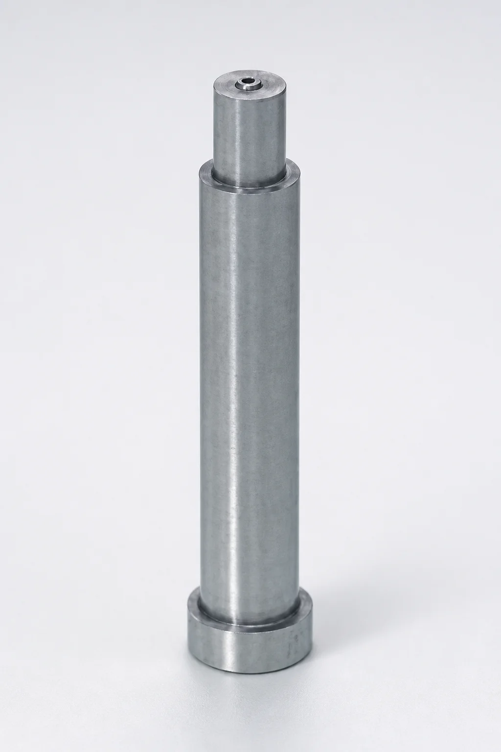
SKH51 Steel Pin-Point Gate Bushings with Head - Round Gate Transition (SR)
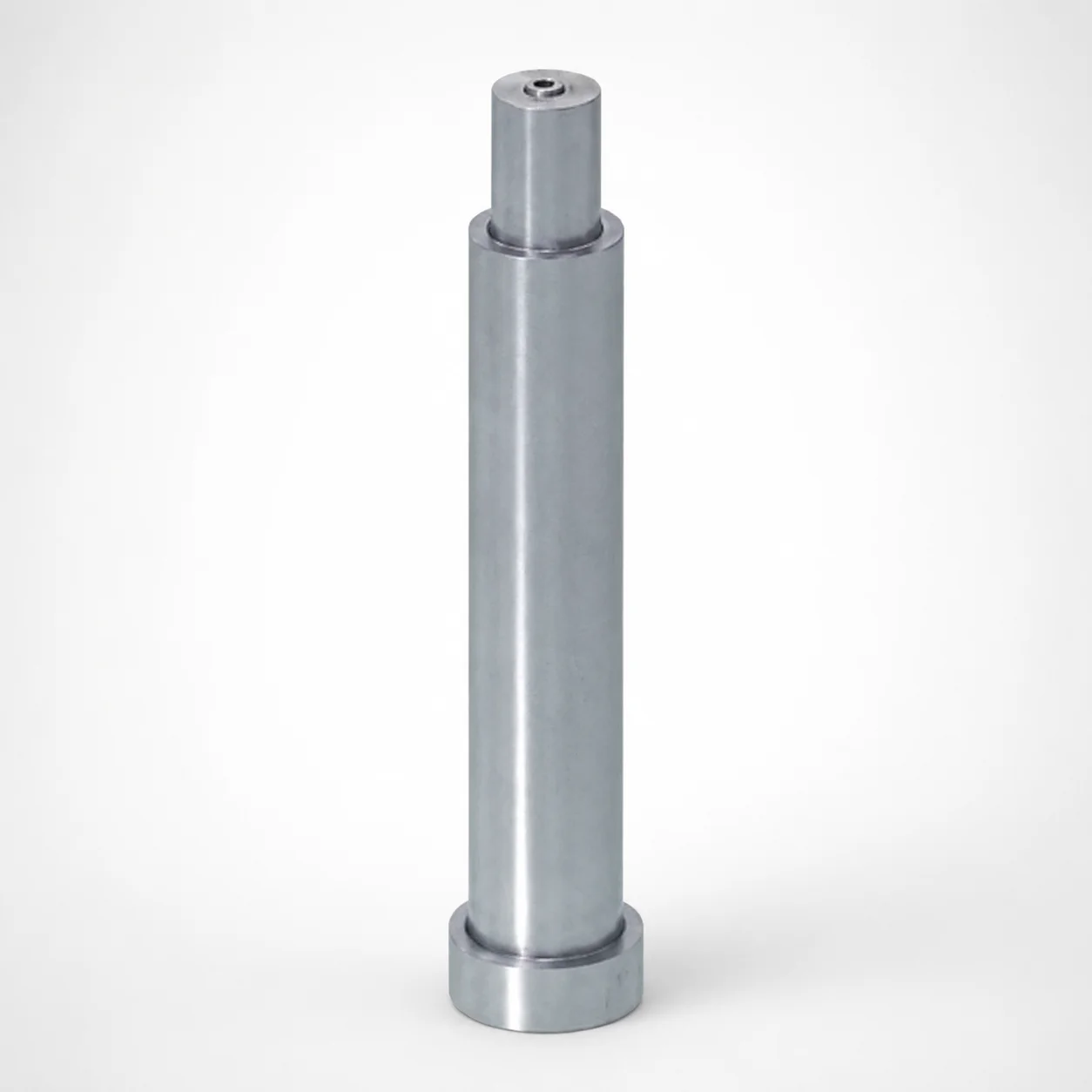
SKH51 Steel Pin-Point Gate Bushings with Head
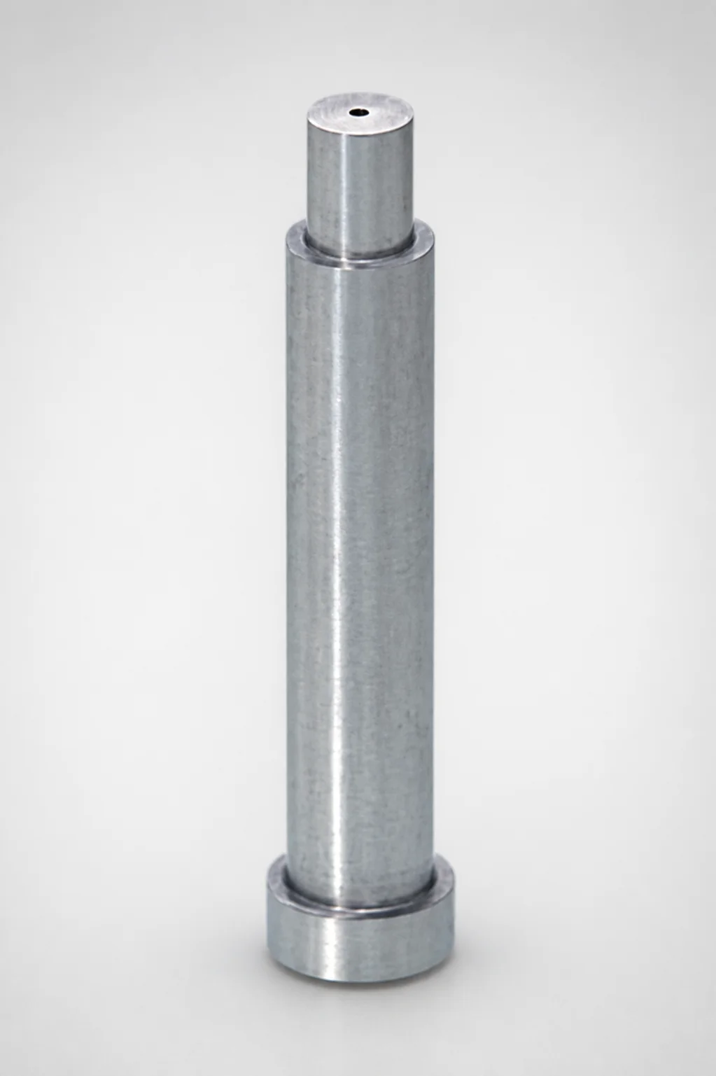
JIS Standard SKH51 Steel Pin-Point Gate Bushings (PGHTBL) with Head
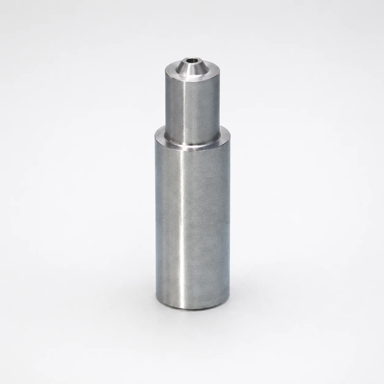
SKH51 Steel Pin-Point Gate Bushings Round Gate Transition SR
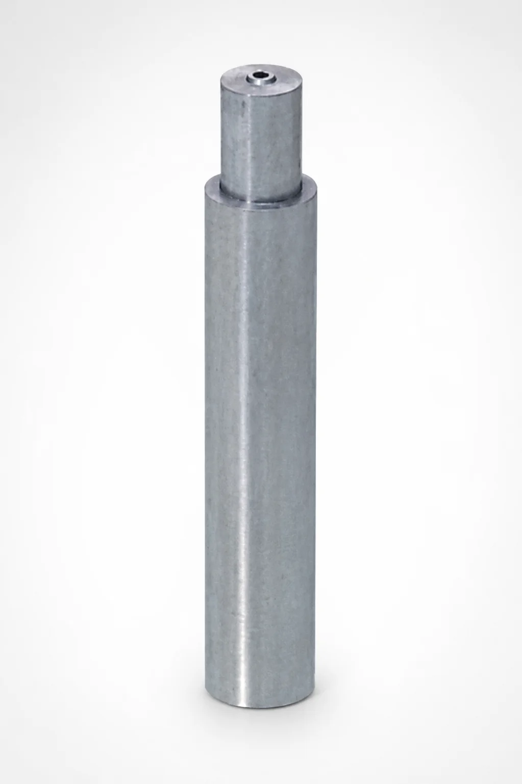
JIS Standard SKH51 Steel Pin-Point Gate Bushings Round Gate Transition SR
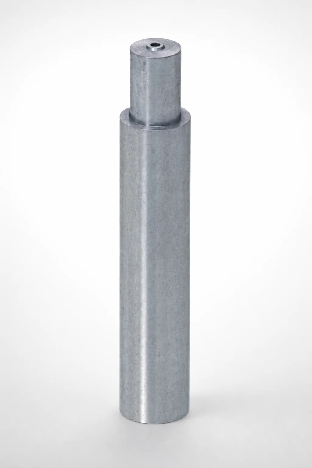
SKH51 Steel Pin-Point Gate Bushings Angle Gate Transition
Need Custom Specifications?
Our engineering team can help with custom configurations, material selection, and volume pricing.